Page 1520 of 1807
SF0HR-01
P11382
ContinuityOhmmeter
P11383
No ContinuityOhmmeter
P11415
Filter Air
E
P11384
FAir
E
Battery
- SFI (2JZ-GTE)VSV FOR EXHAUST GAS CONTROL VALVE
SF-65
1391 Author�: Date�:
1997 SUPRA (RM502U)
INSPECTION
1. REMOVE VSV ASSEMBLY
2. INSPECT VSV FOR OPEN CIRCUIT
Using an ohmmeter, check that there is continuity between the
terminals.
Resistance: 38.5 - 44.5 W at 20°C (68°F)
If there is no continuity, replace the VSV.
3. INSPECT VSV FOR GROUND
Using an ohmmeter, check that there is no continuity between
each terminal and the body.
If there is continuity, replace the VSV.
4. INSPECT VSV OPERATION
(a) Check that air flows from port E to the filter.
(b) Apply battery positive voltage across the terminals.
(c) Check that air flows from port E to F.
If operation is not as specified, replace the VSV.
5. REINSTALL VSV ASSEMBLY
Page 1735 of 1807

SS0DN-02
SS-12
- SERVICE SPECIFICATIONSENGINE MECHANICAL (2JZ-GTE)
169 Author�: Date�:
1997 SUPRA (RM502U)
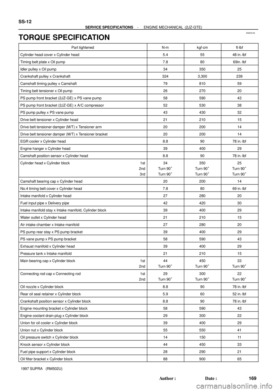
TORQUE SPECIFICATION
Part tightenedN´mkgf´cmft´lbf
Cylinder head cover x Cylinder head5.45548 in.´lbf
Timing belt plate x Oil pump7.88069in.´lbf
Idler pulley x Oil pump3435025
Crankshaft pulley x Crankshaft3243,300239
Camshaft timing pulley x Camshaft7981059
Timing belt tensioner x Oil pump2627020
PS pump front bracket (2JZ-GE) x PS vane pump5859043
PS pump front bracket (2JZ-GE) x A/C compressor5253038
PS pump pulley x PS vane pump4343032
Drive belt tensioner x Cylinder head2121015
Drive belt tensioner damper (M/T) x Tensioner arm2020014
Drive belt tensioner damper (M/T) x Tensioner bracket2020014
EGR cooler x Cylinder head8.89078 in.´lbf
Engine hanger x Cylinder head3940029
Camshaft position sensor x Cylinder head8.89078 in.´lbf
Cylinder head x Cylinder block 1st
2nd
3rd34
Turn 90°
Turn 90°350
Turn 90°
Turn 90°25
Turn 90°
Turn 90°
Camshaft bearing cap x Cylinder head2020014
No.4 timing belt cover x Cylinder head7.88069 in.´lbf
Intake manifold x Cylinder head2728020
Fuel input pipe x Delivery pipe4242030
Intake manifold stay x Intake manifold, Cylinder block3940029
Water outlet x Cylinder head2121015
Air intake chamber x Intake manifold2728020
PS pump rear stay x PS pump bracket3940029
PS vane pump x PS pump bracket5859043
Exhaust manifold x Cylinder head3940029
Pressure tank x Intake manifold2121015
Main bearing cap x Cylinder block 1st
2nd44
Turn 90°450
Turn 90°33
Turn 90°
Connecting rod cap x Connecting rod 1st
2nd29
Turn 90°300
Turn 90°22
Turn 90°
Oil nozzle x Cylinder block8.89078 in.´lbf
Rear oil seal retainer x Cylinder block5.96052 in.´lbf
Crankshaft position sensor x Cylinder block8.89078 in.´lbf
Engine mounting bracket x Cylinder block5859043
Engine coolant drain plug x Cylinder block2930022
Union for oil cooler x Cylinder block3940029
Union nut x Cylinder block5555041
Oil pressure switch x Cylinder block1415011
Knock sensor x Cylinder block4445033
Fuel pipe support x Cylinder block2829021
Oil filter bracket x Cylinder block8890065
Page 1788 of 1807

TC00C-01
P13205
Disconnect
Move49 kpa
SST
P12024
61 - 75 kpa
SST
- TURBOCHARGING (2JZ-GTE)TURBOCHARGER
TC-5
1205 Author�: Date�:
1997 SUPRA (RM502U)
ON-VEHICLE INSPECTION
1. INSPECT INTAKE AIR SYSTEM
Check for leakage or clogging between the air cleaner and
turbocharger inlet and between the turbocharger outlet and cyl-
inder head.
�Clogged air cleaner ..Clean or replace air filter
�Hoses collapsed or deformed .... Repair or replace
�Leakage from connections .... Check each
connection and repair
�Cracks in components .... Check and replace
2. INSPECT EXHAUST SYSTEM
Check for leakage or clogging between the cylinder head and
turbocharger inlet and between the turbocharger outlet and ex-
haust pipe.
�Deformed components .... Repair or replace
�Foreign material in passages .... Remove
�Leakage from components .... Repair or replace
�Cracks in components .... Check and replace
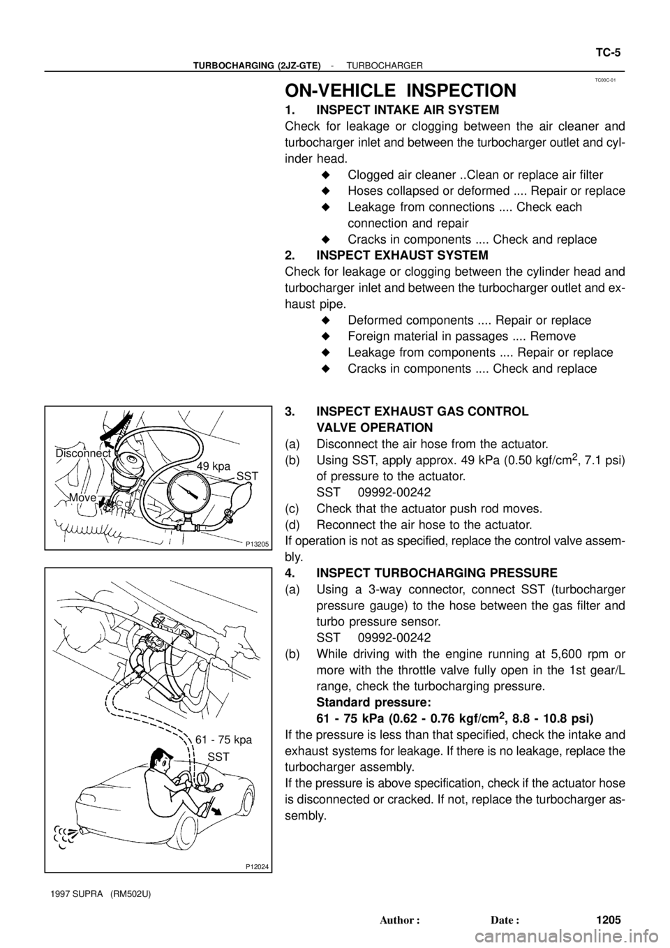
3. INSPECT EXHAUST GAS CONTROL
VALVE OPERATION
(a) Disconnect the air hose from the actuator.
(b) Using SST, apply approx. 49 kPa (0.50 kgf/cm
2, 7.1 psi)
of pressure to the actuator.
SST 09992-00242
(c) Check that the actuator push rod moves.
(d) Reconnect the air hose to the actuator.
If operation is not as specified, replace the control valve assem-
bly.
4. INSPECT TURBOCHARGING PRESSURE
(a) Using a 3-way connector, connect SST (turbocharger
pressure gauge) to the hose between the gas filter and
turbo pressure sensor.
SST 09992-00242
(b) While driving with the engine running at 5,600 rpm or
more with the throttle valve fully open in the 1st gear/L
range, check the turbocharging pressure.
Standard pressure:
61 - 75 kPa (0.62 - 0.76 kgf/cm
2, 8.8 - 10.8 psi)
If the pressure is less than that specified, check the intake and
exhaust systems for leakage. If there is no leakage, replace the
turbocharger assembly.
If the pressure is above specification, check if the actuator hose
is disconnected or cracked. If not, replace the turbocharger as-
sembly.