Page 704 of 1807

DI-289
517 Author�: Date�:
1997 SUPRA (RM502U)
INSPECTION PROCEDURE
TOYOTA hand-held tester
1 Con")
BE6653S03252S03253
A03147
ON
Air
Air
Air Filter
E
E
F
VSV: ON
VSV: OFF
- DIAGNOSTICSENGINE (2JZ-GTE)
DI-289
517 Author�: Date�:
1997 SUPRA (RM502U)
INSPECTION PROCEDURE
TOYOTA hand-held tester
1 Connect the TOYOTA hand-held tester and check operation of VSV for IACV.
PREPARATION:
(a) Connect the TOYOTA hand-held tester to DLC3.
(b) Turn ignition switch ON and TOYOTA hand-held tester
main switch ON.
(c) Select the ACTIVE TEST mode on the TOYOTA hand-
held tester.
CHECK:
Check operation of VSV when VSV is operated by the TOYOTA
hand-held tester.
OK:
VSV is ON:
Air from pipe E flows out through pipe F.
VSV is OFF:
Air from pipe E flows out through the air filter.
OK Check for intermittent problems
(See page DI-147).
NG
2 Check VSV for IACV (See page SF-61).
NG Replace VSV for IACV.
OK
3 Check for open and short in harness and connector between EFI main relay
(Marking: EFI MAIN) and ECM (See page IN-28).
NG Repair or replace harness or connector.
OK
Check and replace ECM (See page IN-28).
Page 710 of 1807
BE6653S03254S03255A06731
ON
Air Air
E
FE
Air Filter
VSV: ON VSV: OFF
- DIAGNOSTICSENGINE (2JZ-GTE)
DI-295
523 Author�: Date�:
1997 SUPRA (RM502U)
INSPECTION PROCEDURE
TOYOTA hand-held tester
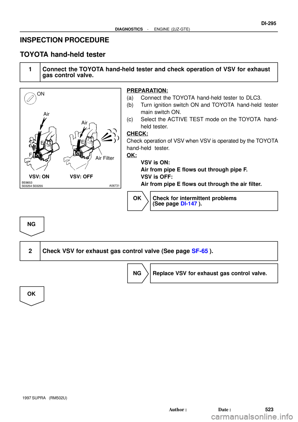
1 Connect the TOYOTA hand-held tester and check operation of VSV for exhaust
gas control valve.
PREPARATION:
(a) Connect the TOYOTA hand-held tester to DLC3.
(b) Turn ignition switch ON and TOYOTA hand-held tester
main switch ON.
(c) Select the ACTIVE TEST mode on the TOYOTA hand-
held tester.
CHECK:
Check operation of VSV when VSV is operated by the TOYOTA
hand-held tester.
OK:
VSV is ON:
Air from pipe E flows out through pipe F.
VSV is OFF:
Air from pipe E flows out through the air filter.
OK Check for intermittent problems
(See page DI-147).
NG
2 Check VSV for exhaust gas control valve (See page SF-65).
NG Replace VSV for exhaust gas control valve.
OK
Page 725 of 1807
A00732
ON
E
Air Filter
E
G VSV: ON
VSV: OFF
DI-310
- DIAGNOSTICSENGINE (2JZ-GTE)
538 Author�: Date�:
1997 SUPRA (RM502U)
INSPECTION PROCEDURE
TOYOTA hand-held tester
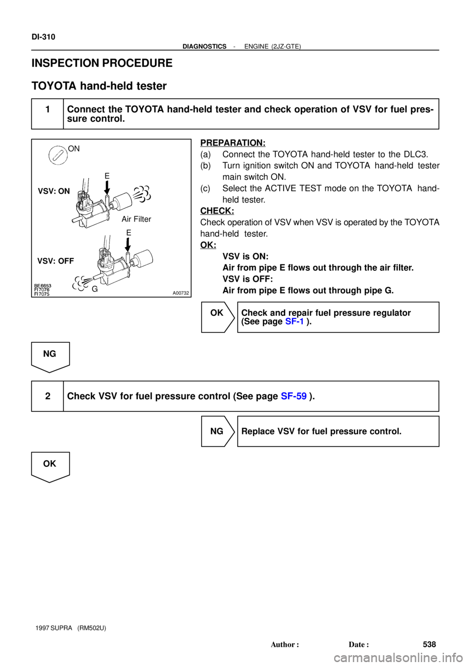
1 Connect the TOYOTA hand-held tester and check operation of VSV for fuel pres-
sure control.
PREPARATION:
(a) Connect the TOYOTA hand-held tester to the DLC3.
(b) Turn ignition switch ON and TOYOTA hand-held tester
main switch ON.
(c) Select the ACTIVE TEST mode on the TOYOTA hand-
held tester.
CHECK:
Check operation of VSV when VSV is operated by the TOYOTA
hand-held tester.
OK:
VSV is ON:
Air from pipe E flows out through the air filter.
VSV is OFF:
Air from pipe E flows out through pipe G.
OK Check and repair fuel pressure regulator
(See page SF-1).
NG
2 Check VSV for fuel pressure control (See page SF-59).
NG Replace VSV for fuel pressure control.
OK
Page 1025 of 1807
![TOYOTA SUPRA 1997 Service Repair Manual Position of Parts in Engine Compartment
[2JZ-GTE]
R 1 Radiator Fan Motor No.1
R 2 Radiator Fan Relay No.1
R 3 Radiator Fan Relay No.2
R20 Radiator Fan Motor No.2
S 1 SFI Resistor
S 2 Starter
S 3 Start](/manual-img/14/57469/w960_57469-1024.png "TOYOTA SUPRA 1997 Service Repair Manual Position of Parts in Engine Compartment
[2JZ-GTE]
R 1 Radiator Fan Motor No.1
R 2 Radiator Fan Relay No.1
R 3 Radiator Fan Relay No.2
R20 Radiator Fan Motor No.2
S 1 SFI Resistor
S 2 Starter
S 3 Start")
Position of Parts in Engine Compartment
[2JZ-GTE]
R 1 Radiator Fan Motor No.1
R 2 Radiator Fan Relay No.1
R 3 Radiator Fan Relay No.2
R20 Radiator Fan Motor No.2
S 1 SFI Resistor
S 2 Starter
S 3 Starter
S 5 Sub Throttle Position Sensor
S18 Sub Throttle Valve Motor
T 1 Theft Deterrent Horn
T 2 Throttle Position Sensor
T14 Turbo Pressure Sensor
V 2 VSV (EGR)
V 3 VSV (EVAP)
V 4 VSV (Exhaust Bypass Valve)
V 5 VSV (Exhaust Gas Control Valve)
V 6 VSV (Fuel Pressure Up)
V 7 VSV (Intake Air Control Valve)
V 8 VSV (Waste Gate Valve)
V10 Vehicle Speed Sensor No.1 (Combination Meter)
V11 Vehicle Speed Sensor No.2 (Electronically
Controlled Transmission)
W 1 Washer Motor I 1 Idle AIr Control Valve
I 2 Igniter
I 3 Igniter
I 6 Ignition Coil No.1
I 7 Ignition Coil No.2
I 8 Ignition Coil No.3
I 9 Ignition Coil No.4
I10 Ignition Coil No.5
I11 Ignition Coil No.6
I12 Injector No.1
I13 Injector No.2
I14 Injector No.3
I15 Injector No.4
I16 Injector No.5
I17 Injector No.6
K 1 Knock Sensor (on Front Side)
K 2 Knock Sensor (on Rear Side)
M 1 Mass Air Flow Meter
N 1 Noise Filter
O 1 O/D Direct Clutch Speed Sensor
O 2 Oil Pressure SW
P 1 PPS Solenoid
P 2 Park/Neutral Position SW, Back-Up Light SW and
A/T Indicator Light SW (A/T)
P13 Parking Light LH
25
G
Page 1027 of 1807
![TOYOTA SUPRA 1997 Service Repair Manual 27
G
Position of Parts in Engine Compartment
[2JZ-GE]
O 2 Oil Pressure SW
P 1 PPS Solenoid
P 2 Park/Neutral Position SW, Back-Up Light SW and
A/T Indicator Light SW (A/T)
P 3 Power Steering Pressure S](/manual-img/14/57469/w960_57469-1026.png "TOYOTA SUPRA 1997 Service Repair Manual 27
G
Position of Parts in Engine Compartment
[2JZ-GE]
O 2 Oil Pressure SW
P 1 PPS Solenoid
P 2 Park/Neutral Position SW, Back-Up Light SW and
A/T Indicator Light SW (A/T)
P 3 Power Steering Pressure S")
27
G
Position of Parts in Engine Compartment
[2JZ-GE]
O 2 Oil Pressure SW
P 1 PPS Solenoid
P 2 Park/Neutral Position SW, Back-Up Light SW and
A/T Indicator Light SW (A/T)
P 3 Power Steering Pressure SW
P13 Parking Light LH
S 2 Starter
S 3 Starter
T 1 Theft Deterrent Horn
T 2 Throttle Position Sensor
V 1 VSV (ACIS)
V 2 VSV (EGR)
V 3 VSV (EVAP)
V 6 VSV (Fuel Pressure Up)
V10 Vehicle Speed Sensor No.1 (Combination Meter)
V11 Vehicle Speed Sensor No.2 (Electronically
Controlled Transmission)
W 1 Washer Motor H 1 Headlight Hi LH
H 2 Headlight Hi RH
H 3 Headlight Lo LH
H 4 Headlight Lo RH
H 8 Horn LH
H 9 Horn RH
I 1 Idle Air Control Valve
I 4 Igniter
I 5 Ignition Coil
I 12 Injector No.1
I 13 Injector No.2
I 14 Injector No.3
I 15 Injector No.4
I 16 Injector No.5
I 17 Injector No.6
K 1 Knock Sensor (on Front Side)
K 2 Knock Sensor (on Rear Side)
M 1 Mass Air Flow Meter
M 2 Main Heated Oxygen Sensor (Bank 1 Sensor 1)
M 3 Main Heated Oxygen Sensor (Bank 2 Sensor 1)
N 1 Noise Filter
Page 1273 of 1807
B02438
EC046-01
EC3069Check Valve (Vacuum Valve)Gasket
P12150
P12175
Z16768
Port C
Compressed
Air
Air AirAir
- EMISSION CONTROL (2JZ-GTE)EVAPORATIVE EMISSION (EVAP) CONTROL SYSTEM
EC-5
1242 Author�: Date�:
1997 SUPRA (RM502U)
EVAPORATIVE EMISSION (EVAP)
CONTROL SYSTEM
INSPECTION
1. VISUALLY INSPECT LINES AND CONNECTIONS
Look for loose connections, sharp bends or damage.
2. VISUALLY INSPECT FUEL TANK
Look for deformation, cracks or fuel leakage.
3. VISUALLY INSPECT FUEL TANK CAP
Check if the cap and/or gasket are deformed or damaged.
If necessary, repair or replace the cap.
4. REMOVE CHARCOAL CANISTER
5. VISUALLY INSPECT CHARCOAL CANISTER
Look for cracks or damage.
6. CHECK FOR CLOGGED FILTER AND STUCK CHECK
VA LV E
(a) Using low pressure compressed air (4.71 kPa (48 gf/cm
2,
0.68 psi)), blow into port C and check that air flows without
resistance from the other ports.
Page 1274 of 1807
EVAPORATIVE EMISSIO")
Z16769
Port A
Compressed
Air
Z16770
Port B
Compressed
Air
Z16771
Port A
Compressed
Air Port C Port B
P12318
Check Valve
Z09444
Black PortBlue Port EC-6
- EMISSION CONTROL (2JZ-GTE)EVAPORATIVE EMISSION (EVAP) CONTROL SYSTEM
1243 Author�: Date�:
1997 SUPRA (RM502U)
(b) Blow air (4.71 kPa (48 gf/cm2, 0.68 psi)) into port A, and
check that air does not flow from the other ports.
(c) Blow air (4.71 kPa (48 gf/cm
2, 0.68 psi)) into port B, and
check that air does not flow from the other ports.
If operation is not as specified, replace the charcoal canister.
7. CLEAN FILTER IN CANISTER
Clean the filter by blowing 294 kPa (3 kgf/cm
2, 43 psi) of com-
pressed air into port C while holding port A and B closed.
NOTICE:
�Do not attempt to wash the canister.
�No activated carbon should come out.
8. REINSTALL CHARCOAL CANISTER
9. INSPECT VSV FOR EVAP
(See page SF-71)
10. REMOVE CHECK VALVE
11. INSPECT CHECK VALVE
(a) Check that air flows from the blue port to the black port.
(b) Check that air does not flow from the black port to the blue
port.
If operation is not as specified, replace the check valve.
12. REINSTALL CHECK VALVE
HINT:
Install the check valve with the black port facing the purge port
side of the throttle body.
Page 1275 of 1807
EXHAUST GAS RECIRCULATION (EGR) SYSTEM
EC-7
1244 Author�: Date�:
1997 SUPRA (RM502U)
EXHAUST GAS RECIRCULATION
(EGR) SYSTEM")
S02980
FilterCap
S02981
Vacuum Gauge
EC047-02
- EMISSION CONTROL (2JZ-GTE)EXHAUST GAS RECIRCULATION (EGR) SYSTEM
EC-7
1244 Author�: Date�:
1997 SUPRA (RM502U)
EXHAUST GAS RECIRCULATION
(EGR) SYSTEM
INSPECTION
1. CHECK AND CLEAN FILTER IN EGR VACUUM
MODULATOR
(a) Remove the cap and 2 filters.
(b) Check the filter for contamination or damage.
(c) Using compressed air, clean the filter.
(d) Reinstall the 2 filters and cap.
HINT:
Install the filter with the coarser surface facing the atmospheric
side (outward).
2. INSTALL VACUUM GAUGE
Using a 3-way connector, connect a vacuum gauge to the hose
between the EGR valve and EGR vacuum modulator.
3. INSPECT SEATING OF EGR VALVE
Start the engine and check that the engine starts and runs at
idle.
4. INSPECT VSV OPERATION WITH COLD ENGINE
(a) M/T
The coolant temperature should be below 50°C (122°F).
(1) Start the engine and check idling.
(2) When idling with the lever shifting in the N position,
press accelerator pedal slowly to hold the engine
speed at 1,600 - 1,800 rpm.
(3) Check that the vacuum gauge indicates zero.
(b) A/T
The coolant temperature should be below 65°C (149°F).
(1) Chock the 4 wheels.
(2) Fully apply the parking brake.
(3) Connect a tachometer to the engine.
(4) Start the engine and check idle.
(5) Keep your foot pressed firmly on the brake pedal.
(6) Shift into the D position. Press the accelerator pedal
slowly to hold the engine speed at 1,600 - 1,800
rpm.
(7) Check that the vacuum gauge indicates zero.
5. INSPECT VSV OPERATION WITH HOT ENGINE
(a) M/T
Warm up the engine. The coolant temperature in 50°C
(122°F) or more.
(1) When idling with the lever shifting in the N position,
press accelerator pedal slowly to hold the engine
speed at 1,600 - 1,800 rpm.
(2) Check that the vacuum gauge indicates low vacu-
um momentarily.