Page 1276 of 1807

S02982
To Intake
Manifold
S02983
Engine Stopped
Air PQ
S02984
Engine at
3,500 rpm
Air PQ EC-8
- EMISSION CONTROL (2JZ-GTE)EXHAUST GAS RECIRCULATION (EGR) SYSTEM
1245 Author�: Date�:
1997 SUPRA (RM502U)
(b) A/T
Warm up the engine. The coolant temperature in 65°C
(149°F) or more.
(1) Chock the 4 wheels.
(2) Fully apply the parking brake.
(3) Connect a tachometer to the engine.
(4) Start the engine and check idling.
(5) Keep your foot pressed firmly on the brake pedal.
(6) Shifting into the D position. Press the accelerator
pedal slowly to hold the engine speed at 1,600 -
1,800 rpm.
(7) Check that the vacuum gauge indicates low vacu-
um.
6. REMOVE VACUUM GAUGE
Remove the vacuum gauge, and reconnect the vacuum hoses
to their proper locations.
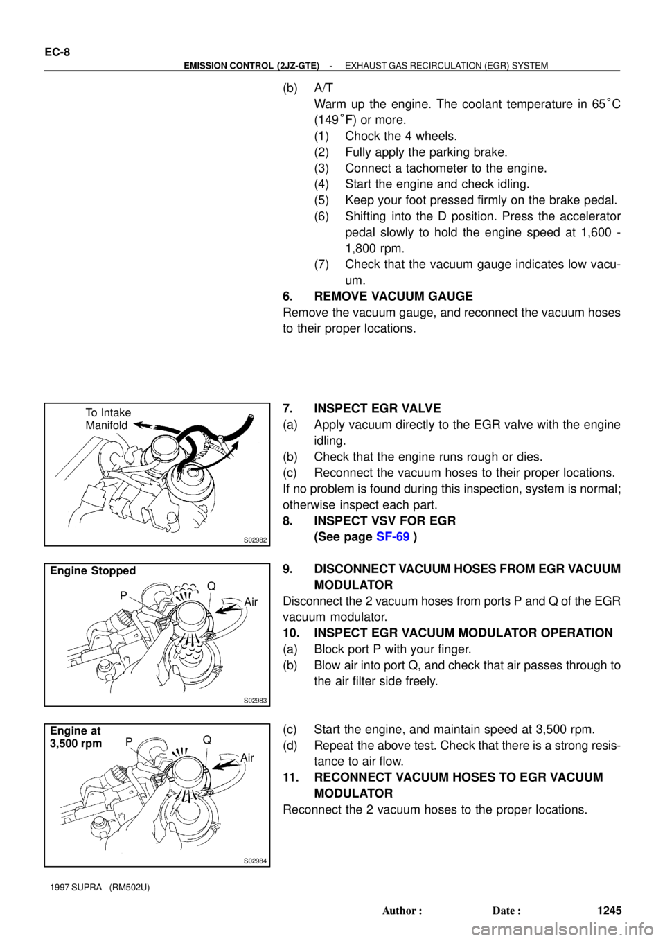
7. INSPECT EGR VALVE
(a) Apply vacuum directly to the EGR valve with the engine
idling.
(b) Check that the engine runs rough or dies.
(c) Reconnect the vacuum hoses to their proper locations.
If no problem is found during this inspection, system is normal;
otherwise inspect each part.
8. INSPECT VSV FOR EGR
(See page SF-69)
9. DISCONNECT VACUUM HOSES FROM EGR VACUUM
MODULATOR
Disconnect the 2 vacuum hoses from ports P and Q of the EGR
vacuum modulator.
10. INSPECT EGR VACUUM MODULATOR OPERATION
(a) Block port P with your finger.
(b) Blow air into port Q, and check that air passes through to
the air filter side freely.
(c) Start the engine, and maintain speed at 3,500 rpm.
(d) Repeat the above test. Check that there is a strong resis-
tance to air flow.
11. RECONNECT VACUUM HOSES TO EGR VACUUM
MODULATOR
Reconnect the 2 vacuum hoses to the proper locations.
Page 1310 of 1807

EM0AV-02
P11544
(2)(3)
(1) EM-58
- ENGINE MECHANICAL (2JZ-GTE)ENGINE UNIT
1163 Author�: Date�:
1997 SUPRA (RM502U)
REMOVAL
1. REMOVE HOOD
2. REMOVE RADIATOR ASSEMBLY
(See page CO-22)
3. DRAIN ENGINE OIL
4. DRAIN FUEL FROM FUEL TANK
5. REMOVE NO.1 AIR HOSE
6. DISCONNECT CONTROL CABLES FROM
THROTTLE BODY
Disconnect these cables:
�Accelerator cable
�Cruise control actuator cable
7. REMOVE AIR CLEANER AND MAF METER
ASSEMBLY
(a) Remove the 3 bolts.
(b) Loosen the hose clamp, disconnect the air hose from the
intake air connector.
(c) Disconnect the MAF meter wire from the clamp on the air
cleaner case.
(d) Disconnect the MAF meter connector, and remove the air
cleaner and MAF meter assembly.
8. M/T:
REMOVE DRIVE BELT TENSIONER DAMPER
(See page EM-15)
9. REMOVE DRIVE BELT, FAN, FLUID COUPLING
ASSEMBLY AND WATER PUMP PULLEY
(See page CO-7)
10. REMOVE CHARCOAL CANISTER
11. DISCONNECT HEATER WATER HOSES
12. DISCONNECT BRAKE BOOSTER VACUUM HOSE
13. DISCONNECT EVAP HOSE
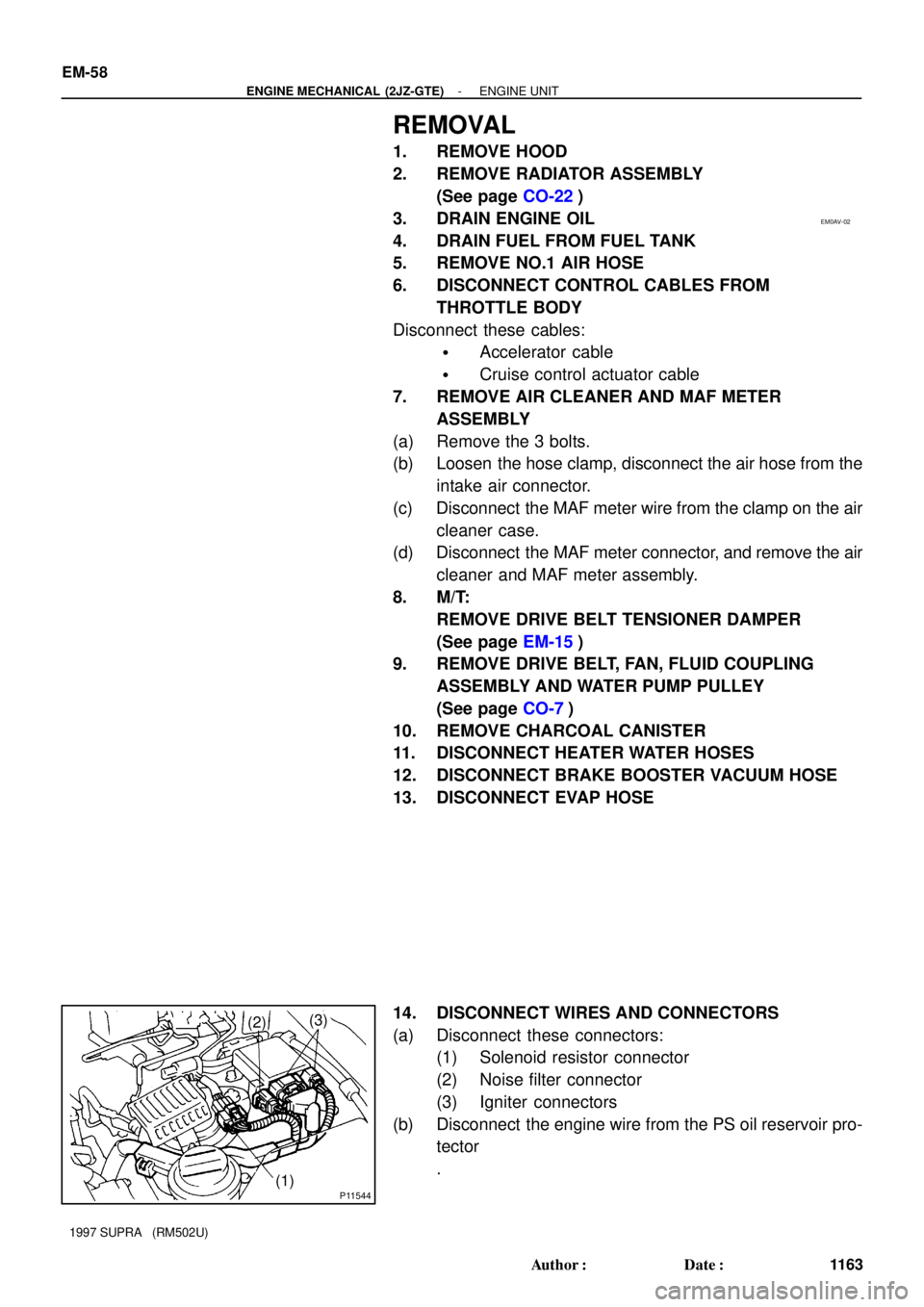
14. DISCONNECT WIRES AND CONNECTORS
(a) Disconnect these connectors:
(1) Solenoid resistor connector
(2) Noise filter connector
(3) Igniter connectors
(b) Disconnect the engine wire from the PS oil reservoir pro-
tector
.
Page 1350 of 1807

EM-2
- ENGINE MECHANICAL (2JZ-GTE)CO/HC
1107 Author�: Date�:
1997 SUPRA (RM502U)
If the CO/HC concentration does not comply with regulations,
troubleshoot in the order given below.
(1) Check heated oxygen sensors operation.
(See page SF-82)
(2) See the table below for possible causes, and then
inspect and correct the applicable causes if neces-
sary.
COHCPhenomenonCauses
NormalHighRough idle1. Faulty ignitions:
�Incorrect timing
�Fouled, shorted or improperly gapped plugs
2. Incorrect valve clearance
3. Leaky EGR valve
4.Leaky intake and exhaust valves
5.Leaky cylinder
LowHighRough idle
(Fluctuating HC reading)1. Vacuum leaks:
�PCV hose
�EGR valve
�Intake manifold
�Air intake chamber
�Throttle body
�IAC valve
�Brake booster line
2. Lean mixture causing misfire
HighHighRough idle
(Black smoke from exhaust)1. Restricted air filter:
2. Faulty SFI system:
�Faulty fuel pressure regulator
�Clogged fuel return line
�Defective ECT sensor
�Defective turbo pressure sensor
�Faulty ECM
�Faulty injector
�Faulty throttle position sensor
�Faulty MAF meter
Page 1368 of 1807

B00319
Recommended Viscosity (SAE):
TEMPERATURE RANGE ANTICIPATED BEFORE NEXT OIL CHANGE °F
°C-20
-29 0
-1820
-740
460
1680
27100
38 10W-30
5W-30 PREFERRED
2JZ-GE
Z09522
Recommended Viscosity (SAE):
10W - 30
5W - 30
-20
-29 -18 -7 4 16 27
38 0 20 40 60 80 100
°C °F
TEMPERATURE RANGE ANTICIPATED BEFORE NEXT OIL CHANGE
2JZ-GTE
LU0JY-01
Z13413
2JZ-GTE
Z16754
2JZ-GTE M/T
P11837
- LUBRICATIONOIL AND FILTER
LU-1
1448 Author�: Date�:
1997 SUPRA (RM502U)
OIL AND FILTER
INSPECTION
1. CHECK OIL QUALITY
Check the oil for deterioration, entry of water, discoloring or thin-
ning.
If oil quality is visibly poor, replace the oil.
Oil grade (2JZ-GE):
API grade SH Energy-Conserving II or SJ, Energy-
Conserving or ILSAC multigrade engine oil.
SAE 5W-30 is the best choice for your vehicle, for
good fuel economy, and good starting in cold weath-
er.
Oil grade (2JZ-GTE):
API grade SH Energy-Conserving II or SJ, Energy-
Conserving or ILSAC multigrade engine oil.
Recommended viscosity is as shown in the illustra-
tion.
2. CHECK ENGINE OIL LEVEL
The oil level should be between the low level and full level marks
on the dipstick.
If low, check for the leakage and add oil up to full level mark.
3. REMOVE ENGINE UNDER COVER
4. 2JZ-GTE:
REMOVE NO.2 AIR TUBE
Loosen the 2 hose clamps, and remove 2 bolts and air tube.
5. 2JZ-GTE M/T:
REMOVE DRIVE BELT TENSION DAMPER
Remove the 2 nuts and tensioner damper.
6. REMOVE DRIVE BELT
Loosen the drive belt tension by turning the drive belt tensioner
clockwise, and remove the drive belt.
Page 1370 of 1807
S00888
Oil Pressure Switch Union Nut
Adhesive
- LUBRICATIONOIL AND FILTER
LU-3
1450 Author�: Date�:
1997 SUPRA (RM502U)
15. REMOVE OIL PRESSURE GAUGE, AND REINSTALL
OIL PRESSURE SWITCH
(a) Remove the oil pressure gauge.
(b) Tighten the union nut.
Torque: 60 N´m (600 kgf´cm, 44 ft´lbf)
(c) Apply adhesive to 2 or 3 thread of the oil pressure switch.
Adhesive:
Part No. 08833-00080, THREE BOND 1344,
LOCKTITE 242 or equivalent
(d) Using SST, install the oil pressure switch.
SST 09816-30010
Torque: 14 N´m (150 kgf´cm, 11 ft´lbf)
(e) Connect the oil pressure switch connector.
16. REINSTALL A/C COMPRESSOR
17. REINSTALL DRIVE BELT
18. START ENGINE AND CHECK FOR REAKS
19. 2JZ-GTE M/T:
INSTALL DRIVE BELT TENSIONER DAMPER
Torque: 20 N´m (200 kgf´cm, 14 ft´lbf)
20. 2JZ-GTE:
REINSTALL NO.2 AIR TUBE
21. REINSTALL ENGINE UNDER COVER
Page 1427 of 1807

MA0688
MA01G-01
- MAINTENANCEENGINE
MA-5
42 Author�: Date�:
1997 SUPRA (RM502U)
ENGINE
INSPECTION
1. REPLACE TIMING BELT
(2JZ-GE: See page EM-17)
(2JZ-GTE: See page EM-19)
2. INSPECT DRIVE BELT
(See page CH-2)
3. REPLACE SPARK PLUGS
(2JZ-GE: See page IG-1)
(2JZ-GTE: See page IG-1)
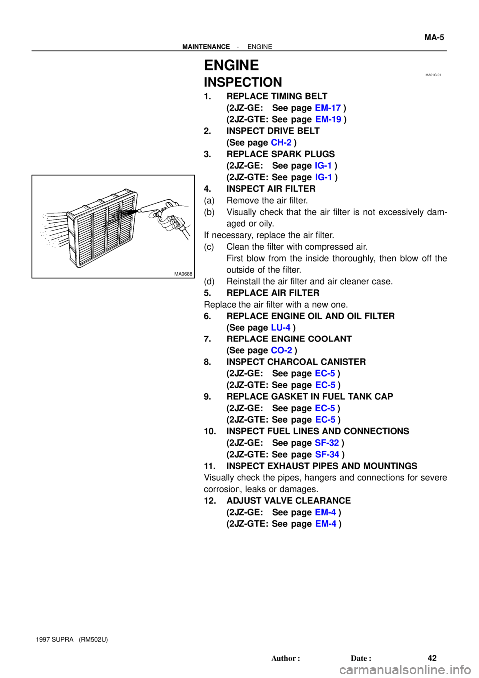
4. INSPECT AIR FILTER
(a) Remove the air filter.
(b) Visually check that the air filter is not excessively dam-
aged or oily.
If necessary, replace the air filter.
(c) Clean the filter with compressed air.
First blow from the inside thoroughly, then blow off the
outside of the filter.
(d) Reinstall the air filter and air cleaner case.
5. REPLACE AIR FILTER
Replace the air filter with a new one.
6. REPLACE ENGINE OIL AND OIL FILTER
(See page LU-4)
7. REPLACE ENGINE COOLANT
(See page CO-2)
8. INSPECT CHARCOAL CANISTER
(2JZ-GE: See page EC-5)
(2JZ-GTE: See page EC-5)
9. REPLACE GASKET IN FUEL TANK CAP
(2JZ-GE: See page EC-5)
(2JZ-GTE: See page EC-5)
10. INSPECT FUEL LINES AND CONNECTIONS
(2JZ-GE: See page SF-32)
(2JZ-GTE: See page SF-34)
11. INSPECT EXHAUST PIPES AND MOUNTINGS
Visually check the pipes, hangers and connections for severe
corrosion, leaks or damages.
12. ADJUST VALVE CLEARANCE
(2JZ-GE: See page EM-4)
(2JZ-GTE: See page EM-4)
Page 1514 of 1807
SF0HL-01
P11340
Ohmmeter
Continuity
P11341
Ohmmeter
No Continuity
P11342
Air
E
G
P11343
Air
E
Filter Battery
- SFI (2JZ-GTE)VSV FOR FUEL PRESSURE CONTROL
SF-59
1385 Author�: Date�:
1997 SUPRA (RM502U)
INSPECTION
1. REMOVE VSV
2. INSPECT VSV FOR OPEN CIRCUIT
Using an ohmmeter, check that there is continuity between the
terminals.
Resistance: 33 - 39 W at 20°C (68°F)
If there is no continuity, replace the VSV.
3. INSPECT VSV FOR GROUND
Using an ohmmeter, check that there is no continuity between
each terminal and the body.
If there is continuity, replace the VSV.
4. INSPECT VSV OPERATION
(a) Check that air flows from port E to G.
(b) Apply battery positive voltage across the terminals.
(c) Check that air flows from port E to the filter.
If operation is not as specified, replace the VSV.
5. REINSTALL VSV
Page 1516 of 1807
SF0HN-01
P11371
Ohmmeter
Continuity
P11372
Ohmmeter
No Continuity
P11414
Air
EFilter
P11373
Air
EBattery
F
- SFI (2JZ-GTE)VSV FOR INTAKE AIR CONTROL VALVE
SF-61
1387 Author�: Date�:
1997 SUPRA (RM502U)
INSPECTION
1. REMOVE VSV
2. INSPECT VSV FOR OPEN CIRCUIT
Using an ohmmeter, check that there is continuity between the
terminals.
Resistance: 38.5 - 44.5 W at 20°C (68°F)
If there is no continuity, replace the VSV.
3. INSPECT VSV FOR GROUND
Using an ohmmeter, check that there is no continuity between
each terminal and the body.
If there is continuity, replace the VSV.
4. INSPECT VSV OPERATION
(a) Check that air flows from port E to the filter.
(b) Apply battery positive voltage across the terminals.
(c) Check that air flows from port E to F.
If operation is not as specified, replace the VSV.
5. REINSTALL VSV