Page 949 of 1807
I02567I02567
Theft Deterrent and
Door Lock ECU
Key Unlock Warning
SwitchT13
12V
Y
20 KSW
IF1 Y11
2 1 W-B J/B No.1
W-B
1K
1J12
1
IE
DI-658
- DIAGNOSTICSTHEFT DETERRENT SYSTEM
886 Author�: Date�:
1997 SUPRA (RM502U)
Key Unlock Warning Switch Circuit
CIRCUIT DESCRIPTION
The key unlock warning switch goes on when the ignition key is inserted in the key cylinder and goes off when
the ignition key is removed.
The ECU operates the key confinement prevention function while the key unlock warning switch is on.
WIRING DIAGRAM
DI4XI-01
Page 950 of 1807
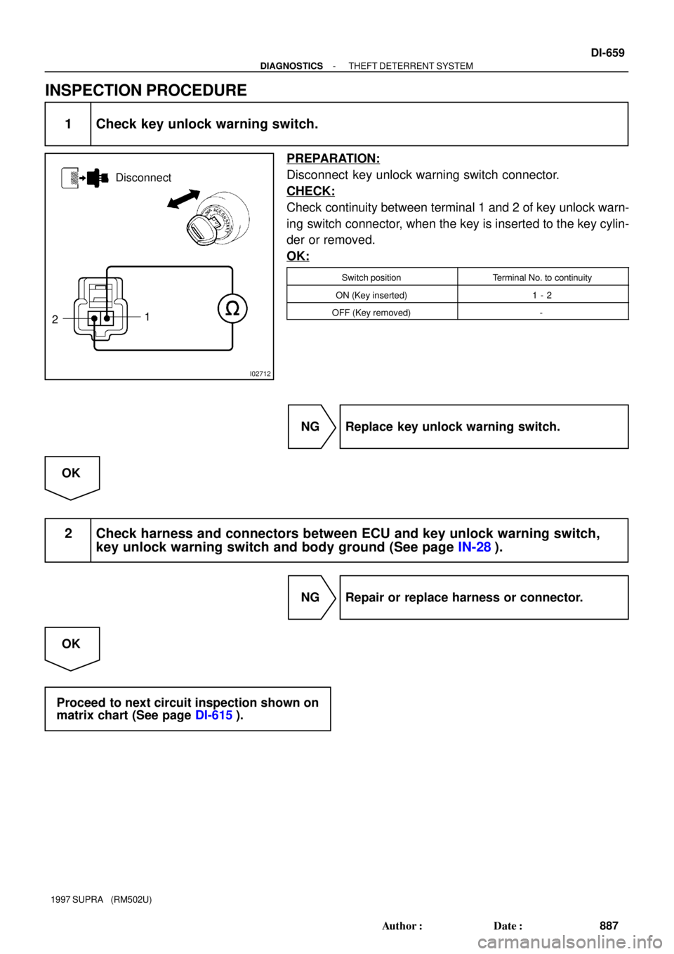
I02712
Disconnect
1
2
- DIAGNOSTICSTHEFT DETERRENT SYSTEM
DI-659
887 Author�: Date�:
1997 SUPRA (RM502U)
INSPECTION PROCEDURE
1 Check key unlock warning switch.
PREPARATION:
Disconnect key unlock warning switch connector.
CHECK:
Check continuity between terminal 1 and 2 of key unlock warn-
ing switch connector, when the key is inserted to the key cylin-
der or removed.
OK:
Switch positionTerminal No. to continuity
ON (Key inserted)1 - 2
OFF (Key removed)-
NG Replace key unlock warning switch.
OK
2 Check harness and connectors between ECU and key unlock warning switch,
key unlock warning switch and body ground (See page IN-28).
NG Repair or replace harness or connector.
OK
Proceed to next circuit inspection shown on
matrix chart (See page DI-615).
Page 1017 of 1807
 or
allowing (2)
current flow.
RESISTOR
An electrical component with a
fixed resistance, placed in a circuit
to reduce voltage to")
18
E
1. NORMALLY
OPEN
Open and
closes circuits,
thereby
stopping (1) or
allowing (2)
current flow.
RESISTOR
An electrical component with a
fixed resistance, placed in a circuit
to reduce voltage to a specific
value.
RESISTOR, TAPPED
A resistor which supplies two or
more different non adjustable
resistance values.
SENSOR (Thermistor)
A resistor which varies its
resistance with temperature.
SHORT PIN
Used to provide an unbroken
connection within a juction block.
SOLENOID
An electromagnetic coil which
forms a magnetic field when
current flows, to move a plunger,
etc.SWITCH, DOUBLE THROW
A switch which continuously
passes cureent through one set of
contacts or the other.
SWITCH,
IGNITION
A key operated switch with several
positions which allows various
circuits, particularly the primary
ignition circuit, to become
operational.
Wires are always
drawn as straight lines
on wiring diagrams.
Crossed wires (1)
without a black dot at
the junction are not
joined;
crossed wires (2) and
a black dot or
octagonal (
) mark at
the juction as spliced
(joined) connections. RELAY, DOUBLE THROW
A relay which passes current
through one set of contacts or the
other.
SENSOR, SPEED
Uses magnetic impulses to open
and close a switch to create a
signal for activation of other
components.TRANSISTOR
A solid state device typically used
as an electronic relay; stops or
passes current depending on the
voltage applied at base.º SWITCH, WIPER PARK
Automatically returns wipers to
the stop position when the wiper
switch is turned off. SWITCH, MANUALSPEAKER
An electromechanical device
which creates sound waves from
current flow.
2. NORMALLY
CLOSED
RESISTOR, VARIABLE or
RHEOSTAT
A controllable resistor with a
variable rate of resistance.
Also called a potentiometer or
rheostat.
2. NORMALLY
OPEN
RELAY
1. NORMALLY
CLOSED
Basically, an electrically
operated switch which
may be normally closed
(1) or open (2). Current
flow through a small
coil creates a magnetic
field which either opens
or closes an attached
switch.
(2) SPLICED
WIRES
(1) NOT
CONNECTED
Page 1029 of 1807

R 5 Radio and Player (w/o S")
29
G
Position of Parts in Instrument Panel
O 5 O/D Main SW and A/T Indicator Illumination
P 4 PPS ECU
P 5 Parking Brake SW
R 4 Radio and Player (w/o Stereo Power Amplifier)
R 5 Radio and Player (w/o Stereo Power Amplifier)
R 6 Radio and Player (w/ Stereo Power Amplifier)
R 7 Remote Control Mirror SW
R 8 Rheostat
S 6 Seat Heater SW
S 7 Shift Lock ECU
S 8 Stereo Power Amplifier
S 9 Stereo Power Amplifier
S10 Stereo Power Amplifier
S11 Stop Light SW
S16 Sub Heated Oxygen Sensor (Bank 1 Sensor 2)
T 5 Telltale Light LH
T 6 Telltale Light RH
T 7 Theft Deterrent and Door Lock Control ECU
T 8 Traction Control SW
T13 Theft Deterrent and Door Lock Control ECU
T15 Throttle ECU
T16 Throttle ECU
U 1 Unlock Warning SW E 8 Electronically Controlled Transmission Pattern
Select SW
E 9 Engine Control Module
E10 Engine Control Module
E11 Engine Coolant Temp. Sensor (A/C System)
F10 Front Tweeter (Speaker) LH
F11 Front Tweeter (Speaker) RH
G 3 Glove Box Light
G 4 Glove Box Light SW
H10 Hazard SW
H11 Heated Oxygen Sensor (Bank 1 Sensor 2)
H12 Heater Control SW
H13 Heater Control SW
I18 Ignition Key Cylinder Light
I19 Ignition SW
I20 Integration Relay
J 1 Junction Connector
J 2 Junction Connector
K 4 Kick Down SW
N 2 Noise Filter
Page 1030 of 1807

30
G ELECTRICAL WIRING ROUTING
Position of Parts in Body
N 3 Noise Filter
P 6 Personal Light
P 7 Power Window Control SW RH
P 8 Power Window Master SW and Door Lock Control
SW LH
P 9 Power Window Motor LH
P10 Power Window Motor RH
R 9 Rear Combination Light LH
R10 Rear Combination Light RH
R11 Rear Side Marker Light LH
R12 Rear Side Marker Light RH
R13 Rear Speaker LH
R14 Rear Speaker RH
R15 Rear Wiper Motor and Relay
R16 Remote Control Mirror and Mirror Heater LH
R17 Remote Control Mirror and Mirror Heater RH
R18 Rear Window Defogger (+)
R19 Rear Window Defogger (-)
T11 Tension Reducer Solenoid LH
T12 Tension Reducer Solenoid RH
W 2 Woofer (Speaker) A31 ABS Speed Sensor Rear LH
A32 ABS Speed Sensor Rear RH
A33 Auto Antenna Motor
D10 Door Courtesy SW LH
D11 Door Courtesy SW RH
D12 Door Key Lock and Unlock SW LH
D13 Door Key Lock and Unlock SW RH
D14 Door Lock Control SW RH
D15 Door Lock Motor and Door Unlock Detection SW LH
D16 Door Lock Motor and Door Unlock Detection SW RH
F12 Front Door Speaker LH
F13 Front Door Speaker RH
F14 Fuel Pump and Sender
F15 Fuel Pump ECU
H14 High Mounted Stop Light
L 1 License Plate Light
L 2 Light Failure Sensor
L 3 Luggage Compartment Key Unlock SW
L 4 Luggage Compartment Light
L 5 Luggage Compartment Light SW
Page 1045 of 1807

POWER STEERING
PRESSURE SW
DOOR LOCK MOTOR AND
DOOR UNLOCK
DETECTION SW LH
DOOR KEY LOCK AND
UNLOCK SW LH
REMOTE CONTROL
MIRROR AND MIRROR
HEATER LH
POWER WINDOW MASTER
SW
PERSONAL LI GHT
AIRBAG
SENSOR
ASSEMBLY
POWER MAIN RELAY
INTEGRATION RELAY
LIGHT CONTROL SW
[COMB. SW]
DI MME R SW
[COMB. SW]
DAYTIME RUNNING
LI GHT RELAY NO . 3MAIN HEATED
OXYGEN SENSOR
(
BANK 1 SENSOR 1)
MAIN HEATED
OXYGEN SENSOR
(
BANK 2 SENSOR 1)
(
E1)
CRUISE CONTROL
ECU
KI CK DOWN SW
CRUISE CONTROL SW
[C OMB . SW ]
UNLOCK WA RNI NG SW
KEY INTERL OCK
SOLENOI D
[UNLOCK WARNING SW]
WIPER AND WASHER SW
[C OMB . SW ]
RHEOSTAT
RE MOTE CO NT ROL
MIRROR SW
TELLTALE LIGHT LH
TURN SIGNAL
FL AS HER I17 E27
E28
I17
I 9
I 2
I 2
I 3
I 3
I 1 B 1 B 1 B 1IJ118
ED E28
4
IE(
E01)
(
E02)
W- B
W- B
IB513
W- B
(
*1) W- B
(
*1)(
*4) BR BR BR
BR
BR
BR
BR BR
BR
BR
W- B
W- B
W- B
W- B
W- B
W- B
W- B
W- B W- BW- B W- B W- B
W- B W- B W- B W- B W- B W- B W- B
W- B
W- B
W- BBR
BR BR BR W- B W- B
(
E1)
(
E2)W- B
W- B
W- B
W- B W- B DA TA L I NK
CONNECTOR 2
DA TA L I NK
CONNECTOR 1
E NGI NE CONTROL
MODULE
(
A/T) BR
(
E03)
I 2W- B
W- B
W- B(
*2)
(
*1)
(
*1)(
*1)
(
*2) SUB HE ATED OXYGE N
SENSOR
(
BANK 1 SENSOR 2)E28
BR A A BR
J 2
JUNCTION
CONNE CTOR
BR
CRUISE CONTROL
ACTUATOR W- B
IB617
W- B
I 9 : * 3
I 4 : * 4
1H13
1K12
1E18
1J1
1K6 1D10
1F6
1G3
IG4
1K5
241
* 4 : 2JZ- GE *2 : USA * 1 : CANADA * 3 : 2JZ- GTE
Page 1046 of 1807

SEAT HEATER
(
PASSENGER S SEAT)
BUCKLE SW RH
DOOR COURTESY SW RH
HIGH BEAM INDICATOR
LIGHT")
STEREO POWER
AMPLIFIER
RADIO AND PLAY ER
BLOWER MOTOR
CONTROL RELAY
SEAT HEATER RELAY
(
PASSENGER' S SEAT)
SEAT HEATER
(
PASSENGER' S SEAT)
BUCKLE SW RH
DOOR COURTESY SW RH
HIGH BEAM INDICATOR
LIGHT [COMB. METER]
TRACTION CONTROL SW
SHIFT LOCK ECU
ELECTRONICALLY
CONTROLLED
TRANSMISSION
PATTERN SELECT SW
O/D MAIN SWSEAT HEATER SW
DA YTIME RUNNING
LIGHT RELAY (
MAIN) (
EP)
(
GND)
HE ATE R CONTROL SW
CI GARETTE LI GHTER
CL O CK
AU TO AN TENNA
CONTROL RELAY GLOVE BOX LIGHT SW
THEFT DETERRENT
AND DOOR LOCK
CONTROL ECU
PPS ECU
DOOR LOCK CONTROL
SW RH RE MOTE CONTROL
MIRROR AND MIRROR
HE A TE R RH
DOOR LOCK MOTOR AND
DOOR UNL OCK
DE TECTION S W RH DOOR KEY LOCK AND
UNLOCK SW RH IG
IH I24 I24 I23
I23
I 2
I11
I10I21
B 2 B 2 I25
B 2 IL116 IF311
IK11
IF114
I18
I18IF
I14(
E2)
(
VER1)COMBINATION
METER
A/C
AMPLIFIER
W- B
(
*2)W- B
(
*1)
W- B
(
*2)
W- B
(
*1)
W- B
(
*3)
W- B
(
A/T)
W- B
(
*1)
W- B
(
*1) W- B
(
*1)W- B
(
*1)W- B
(
*1) W- B
(
*1)
W- B
(
*1)
W- BW- B
W- B W- BR- L W- B W- B W- B
W- B W- B W- B W- B W- B W- BW- B
W- BW- B
W- B W- B W- B W- B W- B W- B W- B W- B
W- B
W- B BR BR BR
A
A
A
A
A
A A
A
W- B W- BW- B
W- B W- B
W- B W- B W- B
JUNCTION
CONNECTOR J 1
I11 : * 3
I 4 : * 4 (
*1)(
*1) (
*6)
(
GND)
(
GND)ABS ECU
W- BW- B
(
A/T)
(
A/T)
DA TA LI NK
CONNECTOR 3 W- B I 3
I14
BR
W- BW- BW- B (
*5)
COMBINATION METER
TELLTALE LIGHT RH
FUEL SENDERI 8
I 3
IE13
BP11
BR BRBR
BR
BR
BR
BR
W- B
I10 : * 3
I 9 : * 4I18 : * 3
I 4 : * 4
I18 : * 3
I 4 : * 4
I11 : * 3
I 1 : * 4
242
J GROUND POINT
Page 1047 of 1807
SEAT HEATER RELAY
(
DRIVER' S SEAT)
SEAT HETER
(
DRIVER' S SEAT)
HI GH MOUN TED STOP
LIGHT
REAR COMBINATION
LIGHT LH
DOOR COURTESY SW LH
LICENSE PLATE
LIGHT
BUCKLE SW LH
FUEL PUMPREAR SIDE MARKER
LIGHT RH
RE AR COMBINATION
LIGHT RH
LUGGAGE COMPARTMENT
KEY UNLOCK SW
REAR SIDE MARKER
LIGHT LH
LI GHT FAI LURE
SEN SOR
FU EL PUMP EC U B 9
B 9
B 3
B 3
B 3
I 7B 5 B 4 B 5 B 4B 7 B 7
BI BJ BQ1 2
W- B
W- B
W- B
W- B
W- B W- BW- B W- B W- BW- B W- B W- B W- B
W- B W- B
(
*1)
W- B
(
*1)
W-B W-B W-B W-B W-B
W- B W- B W- B W- B W- B
W- BW- B
BP12* 1 : CANADA
*2 : USA
* 6 : W/ O STEREO POWER AMPLIFIER * 5 : W/ STEREO POWER AMPLIFIER *3 : 2JZ- GTE
*4 : 2JZ- GE
P OWE R SEA T CONTRO L
SW(
DRIVER' S SEAT)
W- B
BK
W- B
B10 BO13
W- B W- B W- B
W- B
B 6 BM1 2
W- B
W- B
243


SEAT HETER
(
DRIVER S SEAT)
HI GH MOUN TED STOP
LIGHT
REAR COMBINATION
LIGHT LH
DOOR COURTESY SW LH
LICENSE PLATE
LIGHT
BUCKLE SW LH
FUEL PUMPREAR SIDE MARKER
L")