Page 175 of 1807
Z14743
Connector B
Connector AB1
B3
B2B4
A1 A5A3 A2
- BODY ELECTRICALHEADLIGHT AND TAILLIGHT SYSTEM
BE-19
1997 Author�: Date�:
1997 SUPRA (RM502U)
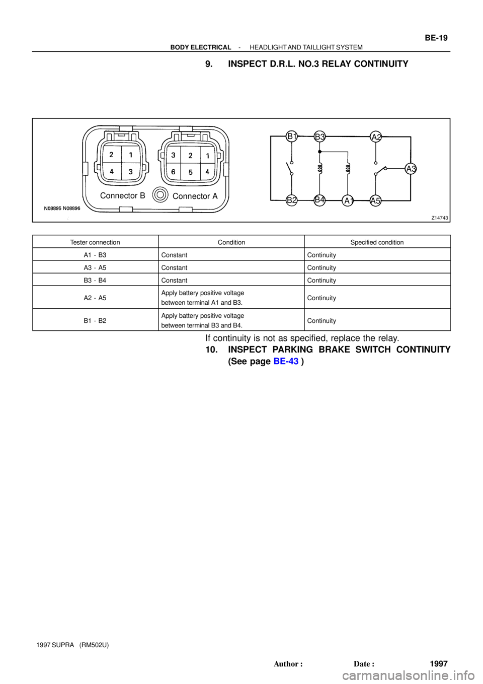
9. INSPECT D.R.L. NO.3 RELAY CONTINUITY
Tester connectionConditionSpecified condition
A1 - B3ConstantContinuity
A3 - A5ConstantContinuity
B3 - B4ConstantContinuity
A2 - A5Apply battery positive voltage
between terminal A1 and B3.Continuity
B1 - B2Apply battery positive voltage
between terminal B3 and B4.Continuity
If continuity is not as specified, replace the relay.
10. INSPECT PARKING BRAKE SWITCH CONTINUITY
(See page BE-43)
Page 195 of 1807
Z18230
Brake Fluid Level Warning Switch
Parking Brake Switch
Telltale Light LH
Telltale Light RHVehicle Speed Sensor
Light Failure Sensor
DOME Fuse
Combination Meter
Door Courtesy Switches GAUGE Fuse
ECU-B Fuse
IGN Fuse
PANEL Fuse
TAIL Fuse Integration
Fuel Sender Gauge
: Engine Coolant Temperature Sensor
: Engine Oil Level Sensor
: Low Oil Pressure Warning Switch
: Park/Neutral Position Switch
: Vehicle Speed Sensor 2JZ-GE2JZ-GTE
1
5
4
3
2 Relay� R/B No.2
J/B No.1
Meter Circuit �
�
�
�
�
�
1
1
5 4
3
2 1
2
3
4
5
BE0E7-01
- BODY ELECTRICALCOMBINATION METER
BE-39
2017 Author�: Date�:
1997 SUPRA (RM502U)
COMBINATION METER
LOCATION
Page 197 of 1807

I02078
Cruise Control Indicator :Fuel Gauge
:Engine Coolant Temperature Gauge
:Tachometer
:Speedometer
D.R.L. :Daytime Running Light
* :Engine Oil Level Delay Circuit
F
E
T
S
F
E
T
S C8
A10
A11
A9
A8
A13
C11
C10
B13
B12
B2
A1
C7
C5
A14
A7
A6
A3
C1
C2
C13
A5P
R
N
D
2
LB4
B10
B6
B7
B8
B11
B1
C9
A16
C4
C6
A15
A2
B3
C12 Fuel Level Warning
MANU Indicator
O/D OFF Indicator
Brake Warning
Bulb Check Relay
TRAC Indicator
Right Turn Indicator
High Beam Indicator
Master Warning
Illumination
SNOW IndicatorLeft Turn Indicator
No. Wire Harness Side
Brake Fluid Level Warning Switch
Parking Brake Switch
USA:TAIL (RH) Fuse, PANEL Fuse
Headlight Dimmer Switch
ECT ECU
Cruise Control ECU
TRAC ECU
Ground (Engine)
Engine Coolant Temperature Sender Gauge
Fuel Sender Gauge
Ground (Signal)
Turn Signal Switch
Starter Relay Generator L Terminal Igniter
Park/Neutral Position Switch (A/T Vehicle) A1
2
3
5
6
7
8
9
10
11
13
14
15
16
BGAUGE Fuse
O/D OFF Switch
USA:TAIL (RH) Fuse, PANEL Fuse
Park/Neutral Position Switch (P)
Park/Neutral Position Switch (N)
ECT ECU
Ground (Power)
Park/Neutral Position Switch (D)
Park/Neutral Position Switch (2)
Park/Neutral Position Switch (L) Park/Neutral Position Switch (R) 1
2
3
6
7
8
10
11
124
13
Engine Oil Level Sensor
Turn Signal Switch
Ground (Power)
Fuel Sender Gauge
GAUGE Fuse
Vehicle Speed Sensor (Terminal 2)
Vehicle Speed Sensor (Terminal 3)
USA:TAIL (RH) Fuse, PANEL Fuse
Light Control Rheostat Telltail Light RH (Terminal 11)
Telltail Light LH (Terminal 1)
Telltail Light LH (Terminal 6) 1
2
6
7
8
10
11
124
135
9 CCANADA:D.R.L. No.3 Relay
Clutch Start Switch (M/T Vehicle)
CANADA:D.R.L. No.3 Relay
CANADA:D.R.L. No.3 Relay
- BODY ELECTRICALCOMBINATION METER
BE-41
2019 Author�: Date�:
1997 SUPRA (RM502U)
Page 204 of 1807

17. INSPECT BR")
N08966
BE1217
Ignition
Switch
BatteryWarning Light
N09510
BE0044
Ignition
Switch
BatteryWarning Light BE-48
- BODY ELECTRICALCOMBINATION METER
2026 Author�: Date�:
1997 SUPRA (RM502U)
17. INSPECT BRAKE FLUID LEVEL WARNING SWITCH
CONTINUITY
(a) Remove the reservoir tank cap and strainer.
(b) Disconnect the connector.
(c) Check that there is no continuity between terminals with
the switch OFF (float up).
(d) Use syphon, etc. to take fluid out of the reservoir tank.
(e) Check that there is continuity between terminals with the
switch ON (float down).
(f) Pour the fluid back in the reservoir tank.
If operation is not as specified, replace the switch.
18. INSPECT BRAKE FLUID LEVEL WARNING LIGHT
(a) Disconnect the connector from the brake fluid warning
switch.
(b) Release the parking brake pedal.
(c) Connect terminals on the wire harness side of the level
warning switch connector.
(d) Start the engine, check that the warning light lights up.
If the warning light does not light up, test the bulb or wire har-
ness.
19. INSPECT PARKING BRAKE SWITCH CONTINUITY
(a) Check that there is continuity between terminal and
switch body with the switch ON (switch pin released).
(b) Check that there is no continuity between terminal and
switch body with the switch OFF (switch pin pushed in).
If operation is not as specified, replace the switch or inspect
ground point.
20. INSPECT PARKING BRAKE WARNING LIGHT
(a) Disconnect the connector from the parking brake switch
and the brake fluid warning switch.
(b) Ground terminal on the wire harness side connector.
(c) Start the engine, check that the warning light lights up.
If the warning light does not light up, test the bulb or inspect wire
harness.
Page 327 of 1807

BRAKE PEDAL
ON-VEHICLE INSPECTION
1. CHECK THA")
R07175
Stop Light Switch
Push Rod
Pedal HeightBR1AW-01
BR4980
A
R00085
Pedal Freeplay
- BRAKEBRAKE PEDAL
BR-7
1807 Author�: Date�:
1997 SUPRA (RM502U)
BRAKE PEDAL
ON-VEHICLE INSPECTION
1. CHECK THAT PEDAL HEIGHT IS CORRECT
Pedal height from asphalt sheet:
154.2 - 164.2 mm (6.071 - 6.465 in.)
If the pedal height is incorrect, adjust it.
2. IF NECESSARY, ADJUST PEDAL HEIGHT
(a) Remove the lower instrument panel and finish panel.
(b) Disconnect the connector from the stop light switch.
(c) Loosen the stop light switch lock nut and remove the stop
light switch.
(d) Loosen the push rod lock nut.
(e) Adjust the pedal height by turning the pedal push rod.
(f) Tighten the push rod lock nut.
Torque: 25 N´m (260 kgf´cm, 19 ft´lbf)
(g) Install the stop light switch and turn it until it lightly con-
tacts the pedal stopper.
(h) Turn the stop light switch back one turn.
(i) Check the clearance (A) between stop lights switch and
pedal.
Clearance: 0.5 - 2.4 mm (0.020 - 0.094 in.)
(j) Tighten the stop light switch lock nut.
(k) Connect the connector to the stop light switch.
(l) Check that the stop lights come on when the brake pedal
is depressed, and go off when the brake pedal is re-
leased.
(m) After adjusting the pedal height, check the pedal freeplay.
If clearance (A) between the stop light switch and the brake
pedal stopper has been adjusted correctly, the pedal freeplay
will meet the specifications.
(n) Install the lower instrument panel and finish panel.
3. CHECK PEDAL FREEPLAY
(a) Stop the engine and depress the brake pedal several
times until there is no more vacuum left in the booster.
(b) Push in the pedal by hand until the second point of resis-
tance begins to be felt, then measure the distance, as
shown.
Pedal freeplay: 1 - 6 mm (0.04 - 0.24 in.)
If incorrect, check the stop light switch clearance. If the clear-
ance is OK, then troubleshoot the brake system.
Page 334 of 1807
R12236
A BR-14
- BRAKEBRAKE MASTER CYLINDER
1814 Author�: Date�:
1997 SUPRA (RM502U)
(c) Place a rag and 2 wooden blocks on the work table and
lightly tap the cylinder flange against the block edges until
the piston drops out of the cylinder.
HINT:
Make sure the distance (A) from the rag to the top of the blocks
is at least 100 mm (3.94 in.).
Page 338 of 1807

INSTALLATION
1. INSTALL BRAKE BOOSTER
(a) Install the booster and a new gasket.
(b)")
BR0GN-03
F03521
SST
Gasket
N00744
SST
- BRAKEBRAKE BOOSTER ASSEMBLY
BR-21
1821 Author�: Date�:
1997 SUPRA (RM502U)
INSTALLATION
1. INSTALL BRAKE BOOSTER
(a) Install the booster and a new gasket.
(b) Install the clevis to the operating rod.
(c) Install and torque the booster installation nuts.
Torque: 13 N´m (130 kgf´cm, 9 ft´lbf)
(d) Insert the clevis pin into the clevis and brake pedal, and
install the clip to the clevis pin.
(e) Install the pedal return spring.
2. ADJUST LENGTH OF BOOSTER PUSH ROD
(a) Install the gasket on the master cylinder.
(b) Set the SST on the gasket, and lower the pin until its tip
slightly touches the piston.
SST 09737-00010
(c) Turn the SST upside down, and set it on the booster.
SST 09737-00010
(d) Measure the clearance between the booster push rod
and pin head (SST).
Clearance: 0 mm (0 in.)
(e) Adjust the booster push rod length until the push rod light-
ly touches the pin head.
HINT:
When adjusting the push rod, depress the brake pedal enough
so that the push rod sticks out.
3. INSTALL PEDAL BRACKET STAY
(a) Install the pedal bracket stay.
(b) Install the bolt and nut.
(c) Install the steering column assembly (See page
SR-21).
4. INSTALL THESE PARTS
�Vacuum hose
�Master cylinder (See page BR-17)
5. FILL BRAKE RESERVOIR WITH BRAKE FLUID AND
BLEED BRAKE SYSTEM (See page BR-5)
6. CHECK FOR FLUID LEAKAGE
7. CHECK AND ADJUST BRAKE PEDAL
(See page BR-7)
8. DO OPERATIONAL CHECK (See page BR-18)
Page 376 of 1807
Center Airbag
Sensor Assembly ABS
Deceleration
Sensor ABS and Traction ECU
(for 2JZ-GTE)Stereo Power
Amplifier Integration
RelayJ/B No. 1Traction ECU
(f")
Shift Lock ECUEngine Control
Module
(Engine ECU)Center Airbag
Sensor Assembly ABS
Deceleration
Sensor ABS and Traction ECU
(for 2JZ-GTE)Stereo Power
Amplifier Integration
RelayJ/B No. 1Traction ECU
(for 2JZ-GTE)
R/B No. 4 Daytime Running
Light Relay (Main)
(for Canada)Blower Control
RelayPPS ECU A/C AmplifierTheft Deterrent
ECU Cruise Control ECU Auto Antenna Control Relay
ABS ECU
(for 2JZ-GE)
Component to be alignedSection of repair manual
for relevant model year
Front Wheels
Suspension and Axle (SA) section
Rear Wheels
Suspension and Axle (SA) section
Propeller Shaft
Propeller Shaft (PR) section
3. DRIVE TRAIN AND CHASSIS2. BRAKE SYSTEM
The brake system is one of the most important safety components. Always follow the directions and
notes given in section BR of the repair manual for the relevant model year when handling brake
system parts.
NOTICE: When repairing the brake master cylinder or TRAC system, bleed the air out of the TRAC
system.
The drive train and chassis are components-that can have great effects on the running performance
and vibration resistance of the vehicle. After installing components in the sections listed in the table
below, perform alignments to ensure correct mounting angles and dimensions. Particularly accurate
repair of the body must also be done to ensure correct alignment.
HINT: Correct procedures and special tools are required for alignment. Always follow the directions
given in the repair manual for the relevant model year during alignment and section DI of this manual.
4. ECU (ELECTRONIC CONTROL UNIT)
Locations of ECUs
INTRODUCTIONIN-8