Page 952 of 1807

DI4XK-01
CRUISE CONTROL SYSTEM Check Sheet
Inspector 's name:
Customer 's Name
Date of VehicleRegistration No.
Registration Year
Frame No.
Odometer Reading / /km
Mile
Condition of
Problem Occurrence
Date of Problem
How Often does
Occurrence
Problem Occur?
Vehicle Speed when
Problem Occurred / /
Continuous Intermittent ( Times a day)
km
Mile Brought in
Auto cancel
occurs� Driving condition
� City driving � Freeway � Up hill � Down hill
� After cancel occurred, did the driver activate cruise control
again?
� Yes � No
� Cancel does not
occur� With brake ON
� Except D position shift
� When control SW turns to CANCEL position
� Cruise control
malfunction� Slip to acceleration side
� Slip to deceleration side
� Hunting occurs
� O/D cut off does not occur
� O/D does not return
� Switch
malfunction� SET � ACCEL � COAST � RESUME � CANCEL
�
� Remains ON � Does not light up � Blinking Symptoms
DTC Check1st Time2nd Time
� Normal Code � Malfunction Code (Code )
� Normal Code � Malfunction Code (Code )
- DIAGNOSTICSCRUISE CONTROL SYSTEM
DI-661
889 Author�: Date�:
1997 SUPRA (RM502U)
CUSTOMER PROBLEM ANALYSIS CHECK
Page 957 of 1807

(2)
(1)
No.
Operation MethodCRUISE MAIN Indicator Light
Blinking PatternDiagnosis
1
3
4
2Turn SET/COAST switch ON
Turn RES/ACC switch ON
Drive at about 40 km/h
(25 mph) or below Turn CANCE")
BE6443
(1)
(2)
(1)
No.
Operation MethodCRUISE MAIN Indicator Light
Blinking PatternDiagnosis
1
3
4
2Turn SET/COAST switch ON
Turn RES/ACC switch ON
Drive at about 40 km/h
(25 mph) or below Turn CANCEL switch ON
Turn stop light switch ON
Depress brake pedal
Turn PNP switch OFF
(Shift to except D position)
Turn clutch switch OFF
(Depress clutch pedal)
Drive at about 40 km/h
(25 mph) or higherSET / COAST switch
circuit is normal
RES / ACC switch circuit
is normal
PNP switch circuit is normal CANCEL switch circuit
is normal
Clutch switch circuit is normal
Vehicle Speed Sensor is
normal
Stop light switch circuit
is normal ON
OFF
0.25 sec.
0.25 sec.
1 sec.Light
ON
OFFLight
ON
OFF Light
ON
OFF Light
ON
OFF Light
ON
OFF Light
Switch OFF
Switch ON
Switch ON
Switch OFF DI-666
- DIAGNOSTICSCRUISE CONTROL SYSTEM
894 Author�: Date�:
1997 SUPRA (RM502U)
5. Using TOYOTA hand-held tester:
INPUT SIGNAL CHECK
HINT:
(1) For check No.1 - No.2
�Turn the ignition switch ON.
(2) For check No.3
�Turn ignition switch ON.
�Shift to D position.
(3) For check No.4
�Jack up the vehicle.
�Start the engine.
�Shift to D position.
(a) Press the control switch to SET/COAST or RES/ACC
position and hold it down or hold it up º1º.
(b) Push the main switch ON º2º.
(c) Check that the CRUISE MAIN indicator light blinks twice
or 3 times repeatedly after 3 seconds.
(d) Turn the SET/COAST or RES/ACC switch OFF.
(e) Operate each switch as listed in the table below.
(f) Read the blinking pattern of the CRUISE MAIN indicator
light.
(g) After performing the check, turn the main switch OFF.
HINT:
When 2 or more signals are input to the ECU, the lowest num-
bered code will be displayed first.
Page 962 of 1807

PROBLEM SYMPTOMS TABLE
SymptomSuspect AreaSee page
Cruise control system does not set.
Cruise control syste")
DI4XP-01
- DIAGNOSTICSCRUISE CONTROL SYSTEM
DI-671
899 Author�: Date�:
1997 SUPRA (RM502U)
PROBLEM SYMPTOMS TABLE
SymptomSuspect AreaSee page
Cruise control system does not set.
Cruise control system does not operate.
Input signal check No.4: OK
1. ECU Power Source Circuit
2. Wire Harness
3. Main Switch Circuit
4. Control Switch Circuit
5. Stop Light Switch Circuit
6. PNP Switch or Clutch Switch Circuit
7. Actuator Control Cable
8. Actuator Motor Circuit
9. Cruise Control ECU
Input signal check No.4: NG
1. Vehicle Speed Sensor Circuit
2. Cruise Control ECU
DI-699
DI-704
DI-682
DI-687
DI-694,
DI-697
DI-710
DI-673
IN-28
DI-679
IIN-28
Indicator light does not light up.
1. Wire Harness
2. CRUISE MAIN Indicator Light Circuit
3. Cruise Control ECU
DI-706
IIN-28
Vehicle speed drop when the cruise control switch turned to SET.
1. Actuator Control Cable
2. ECU Power Source Circuit
3. Idle Signal Circuit
4. Actuator Motor Circuit
5. Cruise Control ECUDI-710
DI-699
DI-685
DI-673
IN-28
Set speed deviates on high or low side.
Input signal check No.4: OK
1. Vehicle Speed Sensor Circuit
2. Actuator Control Cable
3. ECU Power Source Circuit
4. Actuator Motor Circuit
5. Cruise Control ECU
Input signal check No.4: NG
1. Cruise Control ECU
DI-679
DI-710
DI-699
DI-673
IN-28
IN-28
Vehicle speed fluctuates when cruise control switch turn to SET.
1. Vehicle Speed Sensor Circuit
2. Actuator Control Cable
3. Idle Signal Circuit
4. ECT Communication Circuit
5. Actuator Motor Circuit
6. Cruise Control ECUDI-679
DI-710
DI-685
DI-690
DI-673
IN-28
Acceleration response is sluggish when cruise control switch turn
to ºACCELº or ºRESUMEº.
Input signal check No.4: OK
1. Actuator Control Cable
2. Vehicle Speed Sensor Circuit
3. Actuator Motor Circuit
4. Cruise Control ECU
Input signal check No.4: NG
1. Control Switch Circuit
2. Cruise Control ECU
DI-673
DI-679
DI-710
IN-28
DI-682
IN-28
Set speed does not cancel when brake pedal depressed.
Input signal check No.3: OK
1. Cruise Control ECU
Input signal check No.3: NG
1. Stop Light Switch Circuit
2. Cruise Control ECU
IN-28
DI-687
IIN-28
Cruise control does not cancel when transmission is shifted to
except D position. (A/T)
Input signal check No.3: OK
1. Cruise Control ECU
Input signal check No.3: NG
1. PNP Switch Circuit
2. Cruise Control ECU
IIN-28
DI-694
IN-28
Page 966 of 1807

I02715
Cruise Control Actuator
Magnetic ClutchGND4
C4
C43
LBR-Y
R-L17
IB6
8
IB6W-B
R-L
Battery
STOP10
1I
J/B No.1WCruise Control ECU
13
43
21 S11
S11S11
S11
Stop Light SwitchB-W
G-W G-WC16
C16
C1610
16
To Light Failure SensorGND
L
STP-
- DIAGNOSTICSCRUISE CONTROL SYSTEM
DI-675
903 Author�: Date�:
1997 SUPRA (RM502U)
DTC 12 Magnetic Clutch Circuit
CIRCUIT DESCRIPTION
This circuit turns on the magnetic clutch inside the actuator during cruise control operation according to the
signal from the ECU. If a malfunction occurs in the actuator or speed sensor, etc. during cruise control opera-
tion, the rotor shaft between the motor and control plate is released.
When the brake pedal is depressed, the stoplight switch turns on, supplying electrical power to the stoplight.
Power supply to the magnetic clutch is mechanically cut and the magnetic clutch is turned OFF.
When driving downhill, if the vehicle speed exceeds the set speed by 15 km/h (6 mph) above the set speed,
then cruise control at the set speed is resumed.
DTC No.Detection ItemTrouble Area
12Short in magnetic clutch circuit
Open (0.8 sec.) in magnetic clutch circuit
�Cruise contorl actuator magnetic clutch
�Harness or connector between ECU and magnetic clutch,
magnetic clutch and body ground
�Cruise control ECU
WIRING DIAGRAM
DI4XR-01
Page 978 of 1807

N19613
22
1 2
4
3
10 16Cruise Control ECU
1B
I1 S11
S11G-W
B-W
Cruise Control Actuator R/B No.2
Battery
B 2A2
ALT
W-LJ/B No.1
STOP10
C16
L STP-
2 W-L
S11 S11
C16
POWERR-LR-LWStop Light Switch
- DIAGNOSTICSCRUISE CONTROL SYSTEM
DI-687
915 Author�: Date�:
1997 SUPRA (RM502U)
Stop Light Switch Circuit
CIRCUIT DESCRIPTION
When the brake is on, battery positive voltage normally applies through the STOP fuse and stop light switch
to terminal STP- of the ECU, and the ECU turns the cruise control off.
A fail-safe function is provided so that cancel functions normally, even if there is a malfunction in the stop
light signal circuit.
If the harness connected to terminal STP- has an open circuit, terminal STP- will have battery positive volt-
age and the cruise control will be turned off.
Also, when the brake is on, the magnetic clutch is cut mechanically by the stop light switch, turning the cruise
control off. (See page DI-675 for operation of the magnetic clutch)
WIRING DIAGRAM
DI4XX-01
Page 979 of 1807
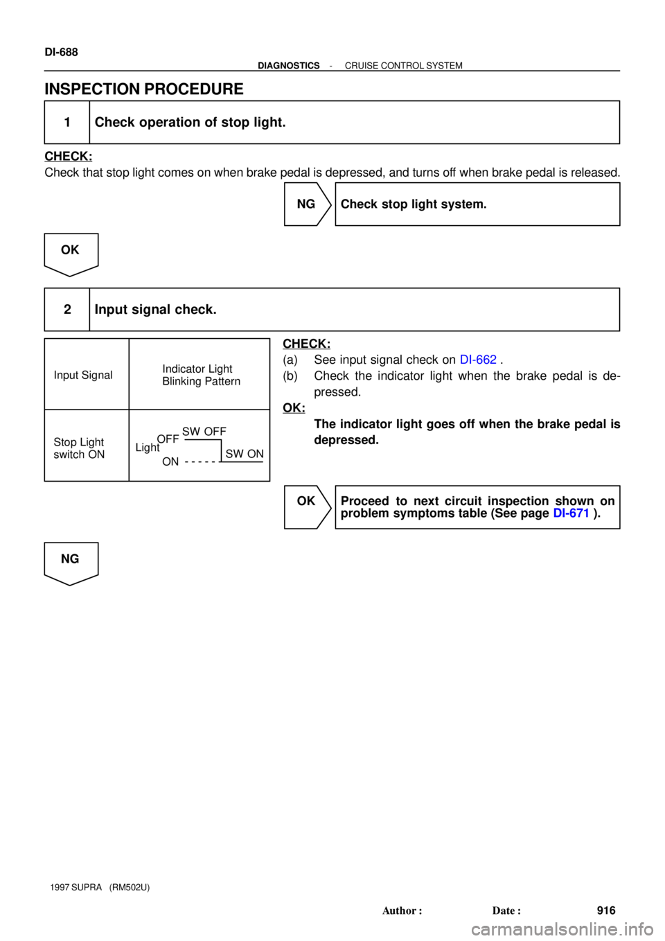
Input SignalIndicator Light
Blinking Pattern
Stop Light
switch ON
LightOFF
ONSW OFF
SW ON
DI-688
- DIAGNOSTICSCRUISE CONTROL SYSTEM
916 Author�: Date�:
1997 SUPRA (RM502U)
INSPECTION PROCEDURE
1 Check operation of stop light.
CHECK:
Check that stop light comes on when brake pedal is depressed, and turns off when brake pedal is released.
NG Check stop light system.
OK
2 Input signal check.
CHECK:
(a) See input signal check on DI-662.
(b) Check the indicator light when the brake pedal is de-
pressed.
OK:
The indicator light goes off when the brake pedal is
depressed.
OK Proceed to next circuit inspection shown on
problem symptoms table (See page DI-671).
NG
Page 980 of 1807
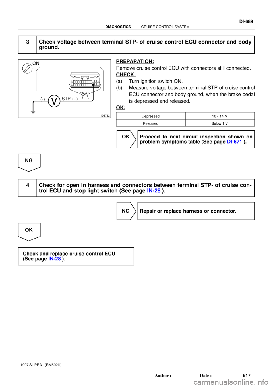
I02722
ON
(-)STP-(+)
- DIAGNOSTICSCRUISE CONTROL SYSTEM
DI-689
917 Author�: Date�:
1997 SUPRA (RM502U)
3 Check voltage between terminal STP- of cruise control ECU connector and body
ground.
PREPARATION:
Remove cruise control ECU with connectors still connected.
CHECK:
(a) Turn ignition switch ON.
(b) Measure voltage between terminal STP-of cruise control
ECU connector and body ground, when the brake pedal
is depressed and released.
OK:
Depressed10 - 14 V
ReleasedBelow 1 V
OK Proceed to next circuit inspection shown on
problem symptoms table (See page DI-671).
NG
4 Check for open in harness and connectors between terminal STP- of cruise con-
trol ECU and stop light switch (See page IN-28).
NG Repair or replace harness or connector.
OK
Check and replace cruise control ECU
(See page IN-28).
Page 1024 of 1807

Position of Parts in Engine Compartment
E 4 Engine Coolant Temp. Sender
E 5 Engine Coolant Temp. SW
E 6 Engine Hood Courtesy SW
E 7 Engine Oil Level Sensor
F 3 Front Fog Light LH
F 4 Front Fog Light RH
F 5 Front Side Marker Light LH
F 6 Front Side Marker Light RH
F 7 Front Turn Signal Light LH
F 8 Front Turn Signal Light RH and Parking Light RH
F 9 Front Wiper Motor
G 1 Generator
G 2 Generator
H 1 Headlight Hi LH
H 2 Headlight Hi RH
H 3 Headlight Lo LH
H 4 Headlight Lo RH
H 5 Heated Oxygen Sensor (Bank 1 Sensor 1)
H 8 Horn LH
H 9 Horn RH A 1 A/C Ambient Temp Sensor
A 2 A/C Condensor Fan Motor
A 3 A/C Triple Pressure SW
(A/C Dual and Single Pressure SW)
A 4 A/C Magnetic Clutch and Lock Sensor
A 5 A/T Fluid Temp. Sensor
A 6 ABS Actuator
A 7 ABS Actuator
A10 ABS Speed Sensor Front LH
A11 ABS Speed Sensor Front RH
B 1 Back-Up Light SW (M/T)
B 2 Brake Fluid Level Warning SW
C 1 Camshaft Position Sensor No.1
C 2 Camshaft Position Sensor No.2
C 3 Crankshaft Position Sensor
C 4 Cruise Control Actuator
D 1 Data Link Connector 1
D 2 Daytime Running Light Relay No.3
D 3 Daytime Running Light Relay No.3
E 1 EGR Gas Temp. Sensor
E 2 Electronically Controlled Transmission Solenoid
E 3 Engine Coolant Temp. Sensor
[2JZ-GTE]
24
26
G ELECTRICAL WIRING ROUTING