Page 1210 of 1807
C 4C10 C6C7C8C11
A 1C13 B7B5B4A14 B2B1
I 2 I 2I14
A A
EB I H E C 2 1 1II1 33
II1 34
2 1
IB2 14 IF1 15
D 6
P 5J 1
E 7
BRAKE FLUID LEVEL
WARNI NG SW
DIODE
ENGI NE OIL
LEVEL SENSOR
JUNCTION
CONNECTORPARKING BRAKE
SW
DAYTIME RUNNING
LI GHT RELAY
(
MAIN)
BRK
PKBDELAYCOMBINATION METER FROM POWER SOURCE SYSTEM (
SEE PAGE 56)
G- W
R- B
L
G- R
L- Y
G- B BR- W
W- B
W- B
G
L- W
Y- G
R- Y
R- G Y- GG BR W- B W- BBR- W BR- W B- W
BR- W
BR- W R- W W- B
Y- G (
*3)
L- WR- Y Y- G R- G
BR- W BR- W B- W B- WG- OG- O
BRAKE
P
R
N
D
2
L
MASTER (
*1) (
*2)
(
*1)
(
*4)
(
*1 *4) (
*1 *3)
(
*2)
FROM A/ T INDI CATOR LIGHT SW
[P ARK/NEUTRAL POSITION SW]
12
18
8
B 2
C C10 , C11 , C12BA
44
R- W
(
*3)
W- B
A
SNOW
A 5IF1 9
P- G P- G
(
*3) (
*3)TO THROTTLE ECU
(
*2)
(
*2)
1
GENERATOR G 2
L
10A
PANEL
1I 8
221
*1 : USA
* 2 : CANADA* 3 : 2JZ- GTE
* 4 : 2JZ- GE
Page 1242 of 1807
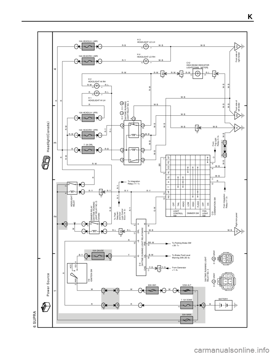
1
234
6 SUPRA
2 1
4 334
12
1H 91J41J 522
1B 51B41H 122222
13 IB2
10 IB2
222ACC
IG1 AM1 4
22 2 22
1 2
1 2
IG2222
1 2
1 2
2IB1
6IF1
14 IF1 13 IB5
EA EB IE 5
1K1
1J 2B 1
22
2 2215175
12 14 322 2 22
7
2
311 1 1 1
6 9 11 13 1 111 1 8 8 13 16C HG OIL PKB E HI
G- WR- Y R- W R
W
R- Y R- YR- WRR
R
R- W
R- Y
R- L
R- W
W- B
W- B W- B
W- B W- B W - B
W- BW- B
W- B
W- B W- B
W- B
R-W R-W R-W R-L
W- B
W- B
W- B W- B W- B
W- B
W- B
R
R- Y R- W
RR- L
R- L
R
R- B R R- W
R- WR- WR- Y R- B
W
R R WR R- L
Y R- L R- Y
11
WR- Y R- Y
10 A GA UGE
R
O HU HF T H EL HL E D FG EF
OFF
TAIL
HEAD
LOW
HIGH
FLAS H
OFF
ON
LIGHT
CONTRO L
SWDIMM ER S WFOG
LIGHT
SW
12 0A ALT 6 0A AM1
7. 5 A DOME
50A MAINB ATTERY F rom Gene rator
<1-4> T o Brake Fluid Lev el
Warn ing SW< 26- 6> To Parking Brake SW
< 26- 7>
I19
IGNI TION SW
IG +B DRL H
D 6
DA YTIME R UNN ING LIGHT REL AY(
MA IN)DIMMER R EL AY
(
DAYTI ME R UNNING
LIGHT RELAY NO. 2)
(
Canada)HEAD LIGH T
RELAY
BR- W
B- W
Y- G
2A
W- BW- B
From Integration
Relay<11- 2> C13
COMBINATION SWFrom
F og Li ght
Relay< 5- 3>DA YTI ME RU NNING
LIGHT RELA Y NO. 3
15A HEAD(
LH- UPR)
15A HEAD(
RH - UPR)
7. 5 A DRLH 1
HE ADL IGHT H I LH H 2
HEA DLIGHT HI RH 15A HE AD(
RH- L WR) 15 A HEA D(
LH- LWR)
H 4
HEADLIGHT LO RHH 3
HE AD LIGHT LO L H
C1 2
HIGH B EAM IND ICATOR
LIGHT[COMB. METER]
To Integration
Relay< 11- 1>
To The ft
Deter ren t
an d Door
Lock Con tr ol
ECU< 14- 3>
B B- Y
BR2
1
Right kic k pa ne lFront sid e of
lef t fenderFront side of
right fend er 2B 4B 1A 5A 1B 3B 2A
3
A D 2 A , D 3 B
7IF2
Y- G
DAY TIME RUN NING L IGHT
RELA Y NO. 3
1
4
5 2
3
612
34 A D 2 G RAY BD 3 GR AY 2
2
W W- B
W- B
Power SourceHeadlight(
Canada)
K
Page 1266 of 1807
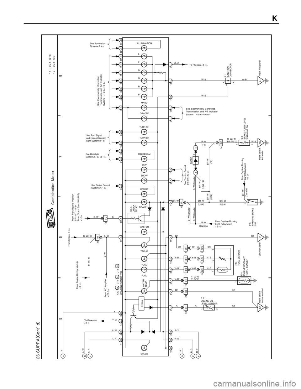
5
678
26 SUPRA(
Cont' d)
11B 4B 14A 9B 13A 16A 6A 2A 3A 15A 6B 1C 4C 10C 6C 7C 8C 11C 12B 13B
3C 13 C 7B 12 C 2C 5A 1A 10B1B2B 5B 8A 9A 8B 10A 11A13 IF2
33 II1 24 II1 19 II1
5 BP1 3 B P1 1 B P 1
2 1
IF1
EB IH 14 IB2 1IE1 2IE1 3 IE115 I F1 29 I I1
EC
See Illumination
Sy stem< 8- 4>
See Turn Signal
and Haza rd War ning
Light Sys tem< 9- 3>
See Headlight
Sys tem< 5- 3> < 6- 4>
See Cr uise Co ntrol
Sys te m< 17- 2>To Rheostat< 8- 4> L
2
D
N
R
P
MA NU
O/D OFF
TURN RH
TURN LH
HIGH B EAM
SN OW
CRUISE
BRAKE
SPE EDFUEL FUEL TACHO MA ST ER
Fr om Engine Cont rol Mo dule
<3- 7>Fro m Ignite r< 2- 4>
DELAYBUL B
CHE CK
REL AY
E 7
ENGINE OIL
L EV EL SEN SOR
E 4
EN GI NE COO LANT
TEMP. SENDERF14
F UEL SEND ER
From Daytime Running
Light Relay(
Main)
<6- 1>P 5
P ARKING BRAK E
SWJ 1
JUNCTION
CO NNECT OR
B 2
BR AKE FL UID LE VEL
WARNIN G SW
BR- WW- B
BR - W
B B- W
B- W(
*2)
B- WW- B W- B
W- B R- W(
*1)
BR - W(
*2)
R- W
BR- W
B- W
BRBR
G BR Y- R Y- GY- BBR BR
Y- B
Y- G Y- GY- BBR
Y- L(
*1)
Y- R(
*2)
GBRBR
R- GR- Y
L- R L- W Y- GY
B- W Y
L- W
L- R
R
R- G
R- YB- W(
Ca nada)
B- W(Ca nada)
BR- WBR - W B- W( Canada)
BR- W
BR- WDIODE
(* 2) (
USA * 1)
(USA)
(
Can ada)
(
Canada)(
US A) (
US A) (
*1)
112
ILLUMINATION
*1 : 2JZ- GTE
*2 : 2JZ- GE
WATER
TEMP .
A A 123 COMB IN ATI O N ME TER C10 B , C1 1 C , C1 2 A
Front side of
intake manifoldLeft kic k pa ne lRight kick pa nel Front side of
le ft fender
G- O
A
1
2 4 4
Combination M eter
A
B
C
D
E
F
To G e ne r a t o r
<1- 4
B- W(
*1)
From A/C Amplifier
<27- 5>
From Dayt ime Running
Lig ht Rela y(
Mai n)
<6- 2>
SLI P
7A
See Tra ction Cont rol
System< 20- 2>
See Electronically Controlled
Transmission and A/T Indicator
System <15-6><16-6>
From Park/Neutral Position
SW (A/T) <1-3>
From Clutch Start SW (M/T)
<1-3>
See Electronically Controlled
Transmission and A/T Indicator
System <15-6><16-6>
K
Page 1423 of 1807
B03050
MA01H-01
MA-6
- MAINTENANCEBRAKE
43 Author�: Date�:
1997 SUPRA (RM502U)
BRAKE
INSPECTION
1. INSPECT BRAKE LINE PIPES AND HOSES
HINT:
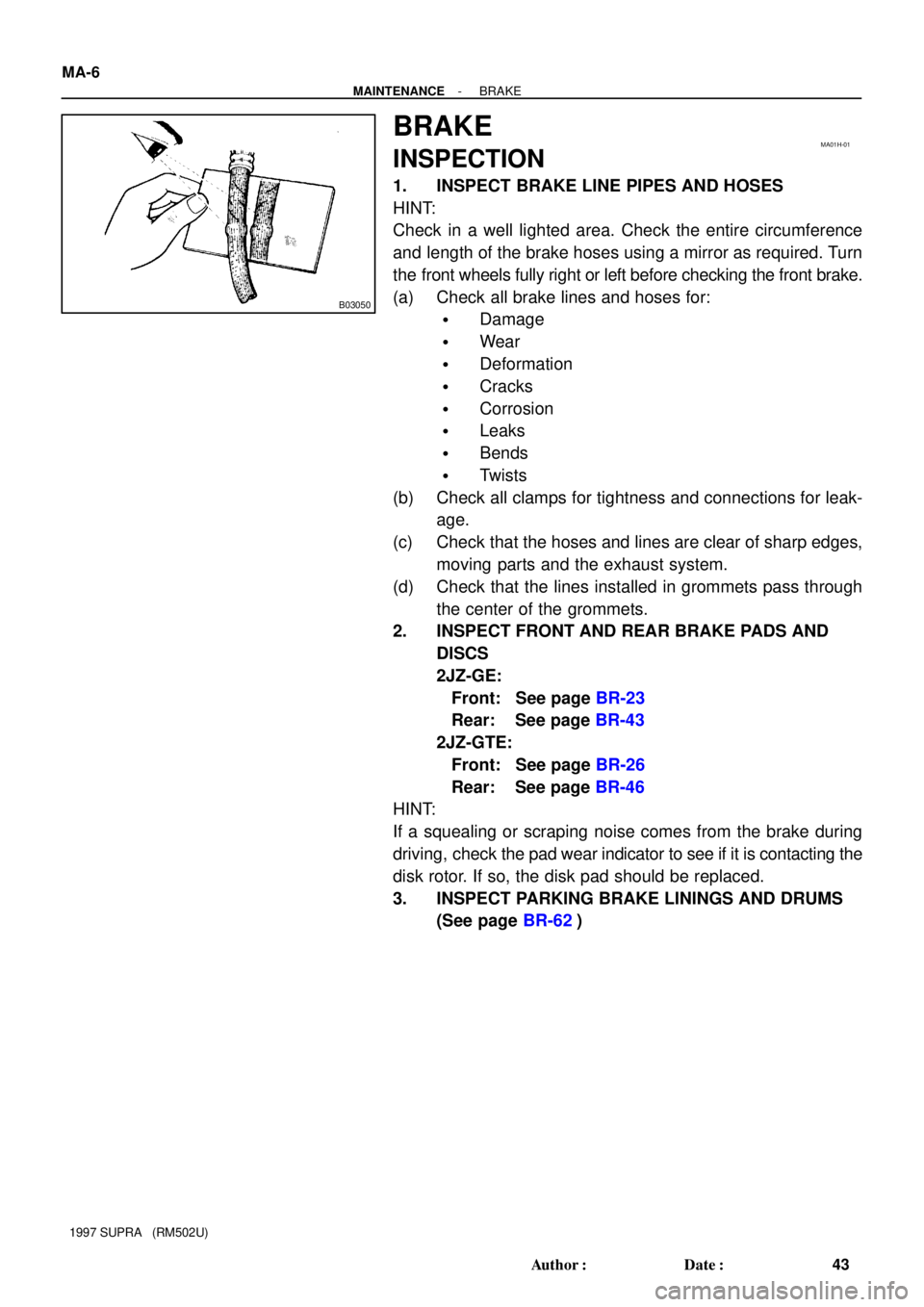
Check in a well lighted area. Check the entire circumference
and length of the brake hoses using a mirror as required. Turn
the front wheels fully right or left before checking the front brake.
(a) Check all brake lines and hoses for:
�Damage
�Wear
�Deformation
�Cracks
�Corrosion
�Leaks
�Bends
�Twists
(b) Check all clamps for tightness and connections for leak-
age.
(c) Check that the hoses and lines are clear of sharp edges,
moving parts and the exhaust system.
(d) Check that the lines installed in grommets pass through
the center of the grommets.
2. INSPECT FRONT AND REAR BRAKE PADS AND
DISCS
2JZ-GE:
Front: See page BR-23
Rear: See page BR-43
2JZ-GTE:
Front: See page BR-26
Rear: See page BR-46
HINT:
If a squealing or scraping noise comes from the brake during
driving, check the pad wear indicator to see if it is contacting the
disk rotor. If so, the disk pad should be replaced.
3. INSPECT PARKING BRAKE LININGS AND DRUMS
(See page BR-62)
Page 1463 of 1807
P12822
Plug
P12089
New
Gasket
FI1654
Fulcrum Length
30 cm
SST
P11303
New
O-Ring
New
Insulator
P12837
Delivery Pipe
O-Ring
Insulator
Intake
ManifoldInjector
Holder
Injector
SpacerInsulator
- SFI (2JZ-GTE)SFI SYSTEM
SF-3
1329 Author�: Date�:
1997 SUPRA (RM502U)
(3) Put a container under the connection.
(4) Slowly loosen the connection.
(5) Disconnect the connection.
(6) Plug the connection with a rubber plug.
(7) Reconnect the fuel pump connector.
(b) When connecting the flare nut or union bolt on the high
pressure pipe union, observe the following procedures:
(1) Union Bolt Type:
Always use a new gasket.
(2) Union Bolt Type:
Tighten the union bolt by hand.
(3) Union Bolt Type:
Tighten the union bolt to the specified torque.
Torque: 29 N´m (300 kgf´cm, 22 ft´lbf)
(4) Flare Nut Type:
Apply a light coat of engine oil to the flare nut and
tighten the flare nut by hand.
(5) Flare Nut Type:
Using SST, tighten the flare nut to the specified
torque.
SST 09631-22020
Torque: 30 N´m (310 kgf´cm, 22 ft´lbf)
HINT:
Use a torque wrench with a fulcrum length of 30 cm (11.81 in.).
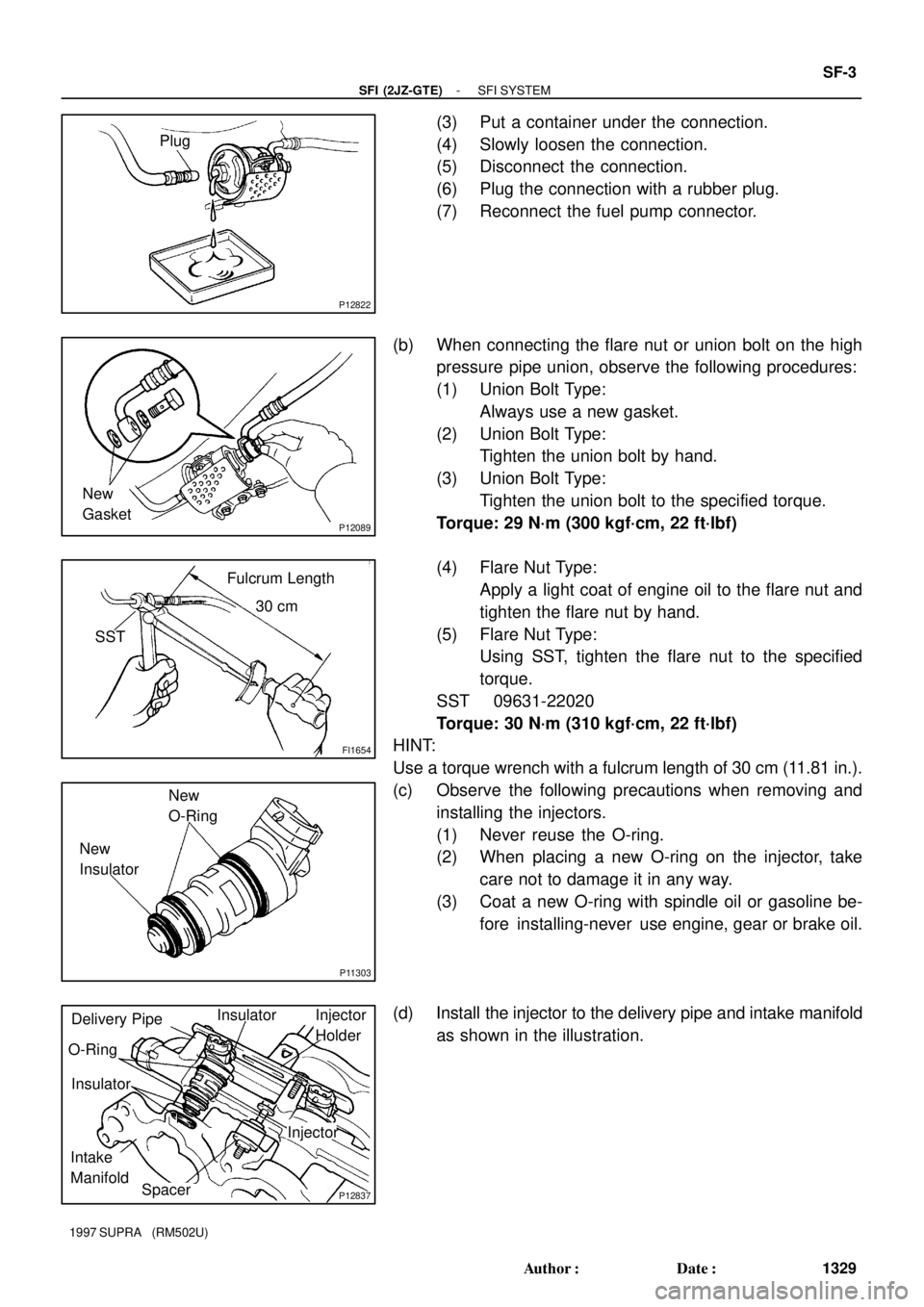
(c) Observe the following precautions when removing and
installing the injectors.
(1) Never reuse the O-ring.
(2) When placing a new O-ring on the injector, take
care not to damage it in any way.
(3) Coat a new O-ring with spindle oil or gasoline be-
fore installing-never use engine, gear or brake oil.
(d) Install the injector to the delivery pipe and intake manifold
as shown in the illustration.
Page 1669 of 1807
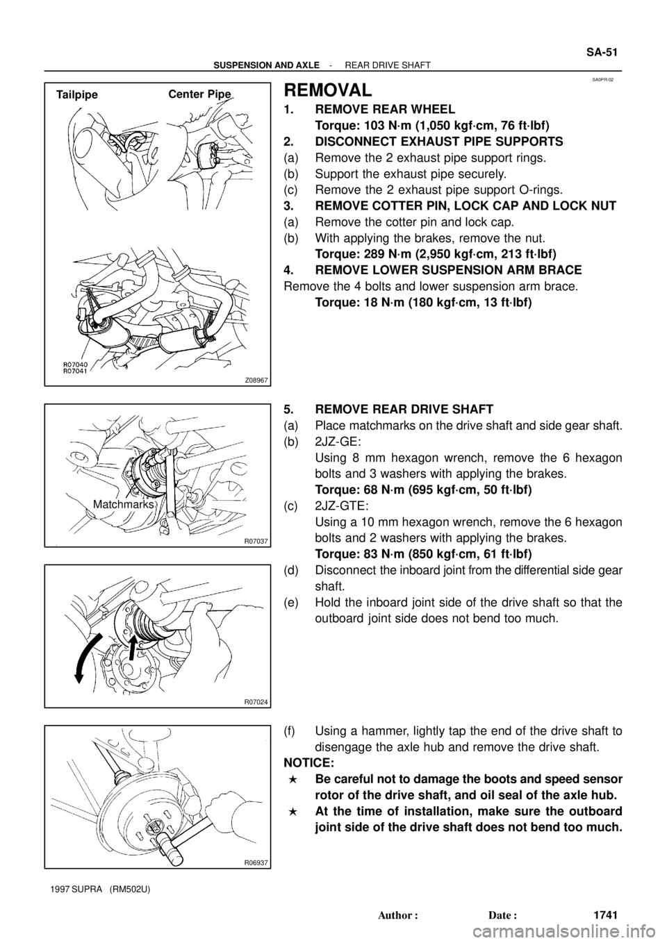
SA0PR-02
Z08967
TailpipeCenter Pipe
R07037
Matchmarks
R07024
R06937
- SUSPENSION AND AXLEREAR DRIVE SHAFT
SA-51
1741 Author�: Date�:
1997 SUPRA (RM502U)
REMOVAL
1. REMOVE REAR WHEEL
Torque: 103 N´m (1,050 kgf´cm, 76 ft´lbf)
2. DISCONNECT EXHAUST PIPE SUPPORTS
(a) Remove the 2 exhaust pipe support rings.
(b) Support the exhaust pipe securely.
(c) Remove the 2 exhaust pipe support O-rings.
3. REMOVE COTTER PIN, LOCK CAP AND LOCK NUT
(a) Remove the cotter pin and lock cap.
(b) With applying the brakes, remove the nut.
Torque: 289 N´m (2,950 kgf´cm, 213 ft´lbf)
4. REMOVE LOWER SUSPENSION ARM BRACE
Remove the 4 bolts and lower suspension arm brace.
Torque: 18 N´m (180 kgf´cm, 13 ft´lbf)
5. REMOVE REAR DRIVE SHAFT
(a) Place matchmarks on the drive shaft and side gear shaft.
(b) 2JZ-GE:
Using 8 mm hexagon wrench, remove the 6 hexagon
bolts and 3 washers with applying the brakes.
Torque: 68 N´m (695 kgf´cm, 50 ft´lbf)
(c) 2JZ-GTE:
Using a 10 mm hexagon wrench, remove the 6 hexagon
bolts and 2 washers with applying the brakes.
Torque: 83 N´m (850 kgf´cm, 61 ft´lbf)
(d) Disconnect the inboard joint from the differential side gear
shaft.
(e) Hold the inboard joint side of the drive shaft so that the
outboard joint side does not bend too much.
(f) Using a hammer, lightly tap the end of the drive shaft to
disengage the axle hub and remove the drive shaft.
NOTICE:
�Be careful not to damage the boots and speed sensor
rotor of the drive shaft, and oil seal of the axle hub.
�At the time of installation, make sure the outboard
joint side of the drive shaft does not bend too much.