Page 779 of 1807
F03346F03347F03348
2JZ-GE Engine (NORMAL ABS):
2JZ-GTE Engine (SPORT ABS):Battery
ABS Control RelayJ/B No.1
(Motor
Relay)
(Solenoid
Relay)
W-B
1
2
6
A9
4
3
1
4
A9B-R
EA1
6
23 B-R
22
DLC1 Short Pin
L16
IJ1
A18
4
LLL
IF212
L42
ABS
Warning
Light
Y
GAUGE
ABS ECU1J1E
512
25
ABS ActuatorABS ECU
12 V
WA
EA
Battery
R/B No.5
ABS
Solenoid Relay15
5
5555 26
4
5 3
W-B
EA
ABS Actuator
B-R
EA16
23 B-R
Short Pin
DLC1
22L16
IJ1L
L
L11A20WA12 V ABS ECU
ABS
Warning
Light
L4
IF212
2 Y
GAUGE J/B No.1
1J
1E
12 5
ABS & TRAC
ECU DI-488
- DIAGNOSTICSANTI-LOCK BRAKE SYSTEM
716 Author�: Date�:
1997 SUPRA (RM502U)
ABS Warning Light Circuit
CIRCUIT DESCRIPTION
If the ECU detects trouble, it lights the ABS warning light while at the same time prohibiting ABS control. At
this time, the ECU records a DTC in memory.
After removing the short pin of the DLC1, connect terminals Tc and E1 of the DLC1 or DLC2 to make the
ABS warning light to blink and output the DTC.
WIRING DIAGRAM
DI4VL-01
Page 780 of 1807

(-) LOCK
- DIAGNOSTICSANTI-LOCK BRAKE SYSTEM
DI-489
717 Author�: Date�:
1997 SUPRA (RM502U)
INSPECT")
F02629F03349F03350
LOCK
Open
ContinuityA8A9
Continuity
F02629F03351F03352
OpenContinuity
A8 A9
(+)
(-) LOCK
- DIAGNOSTICSANTI-LOCK BRAKE SYSTEM
DI-489
717 Author�: Date�:
1997 SUPRA (RM502U)
INSPECTION PROCEDURE
2JZ-GE Engine:
Troubleshooting in accordance with the chart below for each trouble symptom.
ABS warning light does not light upGo to step 1
ABS warning light remains onGo to step 3
1 Check ABS warning light.
See Combination Meter Troubleshooting on page BE-2.
NG Replace bulb or combination meter assembly.
OK
2 Check ABS control (solenoid) relay.
PREPARATION:
Disconnect the connectors from ABS control (solenoid) relay.
CHECK:
Check continuity between each terminal of ABS control (sole-
noid) relay.
OK:
Terminals A9 - 1 and A8 - 3Continuity (Reference value 80 W)
Terminals A9 - 5 and A9 - 6Continuity
Terminals A9 - 2 and A9 - 5Open
CHECK:
(a) Apply battery positive voltage between terminals A9 - 1
and A8 - 3.
(b) Check continuity between each terminal of ABS solenoid
relay.
OK:
Terminals A9 - 5 and A9 - 6Open
Terminals A9 - 2 and A9 - 5Continuity
Page 781 of 1807
F02629F03353F03354
LOCK
(+)
(-)A9
DI-490
- DIAGNOSTICSANTI-LOCK BRAKE SYSTEM
718 Author�: Date�:
1997 SUPRA (RM502U)
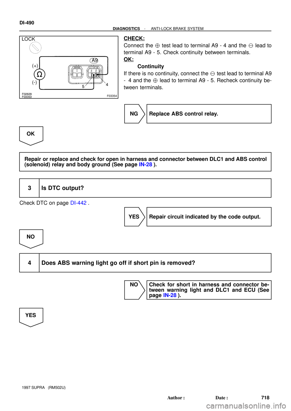
CHECK:
Connect the � test lead to terminal A9 - 4 and the � lead to
terminal A9 - 5. Check continuity between terminals.
OK:
Continuity
If there is no continuity, connect the � test lead to terminal A9
- 4 and the � lead to terminal A9 - 5. Recheck continuity be-
tween terminals.
NG Replace ABS control relay.
OK
Repair or replace and check for open in harness and connector between DLC1 and ABS control
(solenoid) relay and body ground (See page IN-28).
3 Is DTC output?
Check DTC on page DI-442.
YES Repair circuit indicated by the code output.
NO
4 Does ABS warning light go off if short pin is removed?
NO Check for short in harness and connector be-
tween warning light and DLC1 and ECU (See
page IN-28).
YES
Page 782 of 1807
F02629F03355
F03356
LOCK
Open
Continuity
Continuity
- DIAGNOSTICSANTI-LOCK BRAKE SYSTEM
DI-491
719 Author�: Date�:
1997 SUPRA (RM502U)
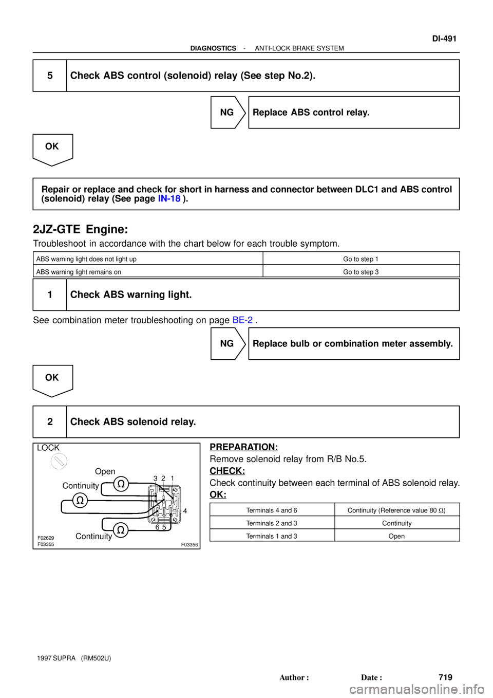
5 Check ABS control (solenoid) relay (See step No.2).
NG Replace ABS control relay.
OK
Repair or replace and check for short in harness and connector between DLC1 and ABS control
(solenoid) relay (See page IN-18).
2JZ-GTE Engine:
Troubleshoot in accordance with the chart below for each trouble symptom.
ABS warning light does not light upGo to step 1
ABS warning light remains onGo to step 3
1 Check ABS warning light.
See combination meter troubleshooting on page BE-2.
NG Replace bulb or combination meter assembly.
OK
2 Check ABS solenoid relay.
PREPARATION:
Remove solenoid relay from R/B No.5.
CHECK:
Check continuity between each terminal of ABS solenoid relay.
OK:
Terminals 4 and 6Continuity (Reference value 80 W)
Terminals 2 and 3Continuity
Terminals 1 and 3Open
Page 784 of 1807
- DIAGNOSTICSANTI-LOCK BRAKE SYSTEM
DI-493
721 Author�: Date�:
1997 SUPRA (RM502U)
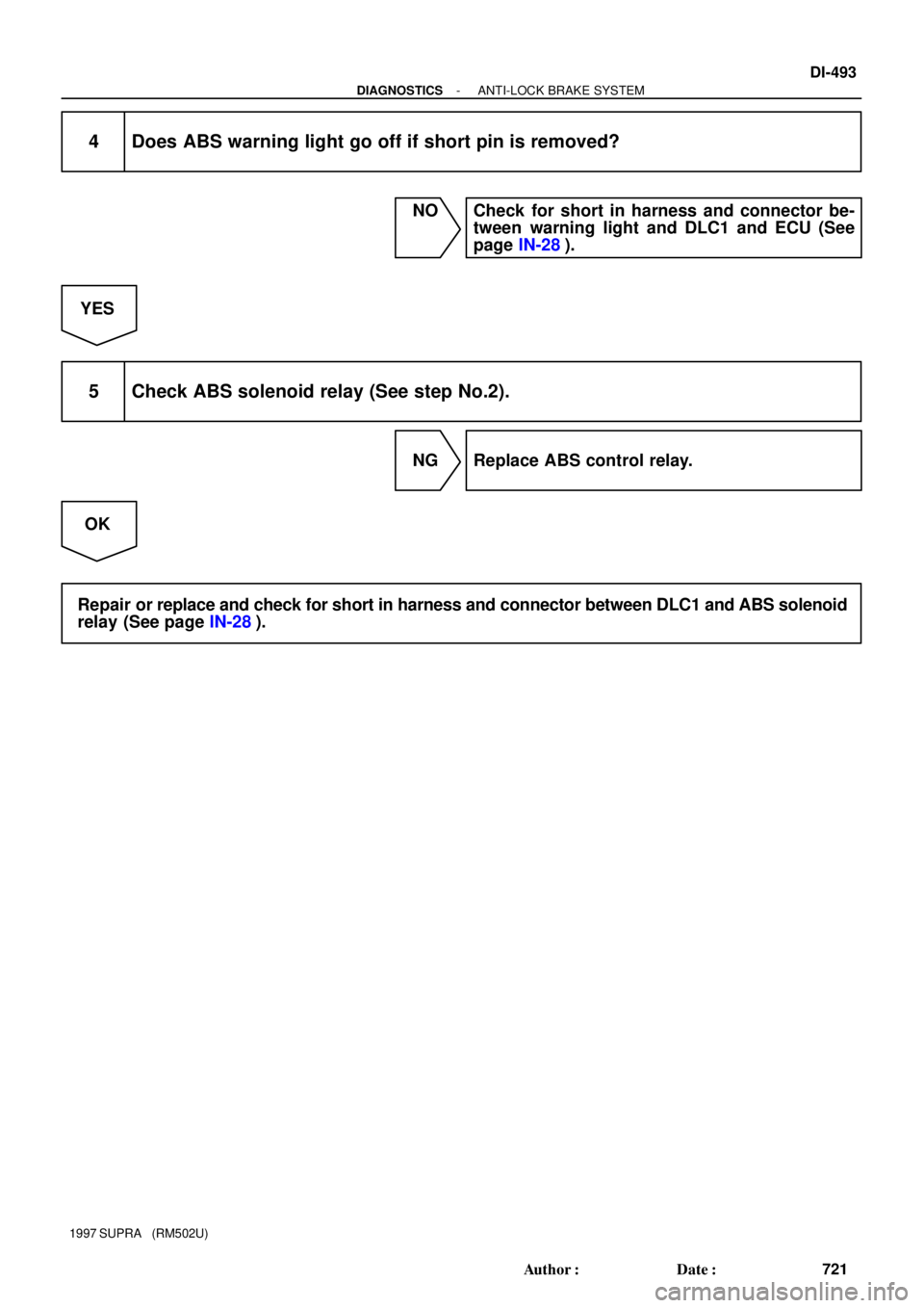
4 Does ABS warning light go off if short pin is removed?
NO Check for short in harness and connector be-
tween warning light and DLC1 and ECU (See
page IN-28).
YES
5 Check ABS solenoid relay (See step No.2).
NG Replace ABS control relay.
OK
Repair or replace and check for short in harness and connector between DLC1 and ABS solenoid
relay (See page IN-28).
Page 785 of 1807
F03361
ABS ECU
12 V
Tc
A20 A1998
*1 *2
R
R
R
IF1
11
P-B
II1 DLC1
R
*121*2P-B R
*1
*2
DLC2
11 Tc E
13
BR
BR BR
ED
IJ1 18BR
Tc E
134
NORMAL ABS (2JZ-GE Engine)
SPORT ABS (2JZ-GTE Engine)
*1:
*2:
S-17-1 Iei-23-1-A
F00041
DLC2
DLC1
E1Tc
E1
Tc
DI-494
- DIAGNOSTICSANTI-LOCK BRAKE SYSTEM
722 Author�: Date�:
1997 SUPRA (RM502U)
Tc Terminal Circuit
CIRCUIT DESCRIPTION
Connecting terminals Tc and E1 of the DLC1 or the DLC1 or the DLC2 causes the ECU to display the DTC
by flashing the ABS warning light.
WIRING DIAGRAM
INSPECTION PROCEDURE
1 Check voltage between terminals Tc and E1 of DLC2 or DLC1.
PREPARATION:
Turn ignition switch ON.
CHECK:
Measure voltage between terminals Tc and E1 of DLC2 or
DLC1.
OK:
Voltage: 10 - 14 V
OK If ABS warning light does not blink even after Tc
and E1 are connected, the ECU may be defec-
tive.
NG
DI4VM-01
Page 787 of 1807
F03362
ABS ECU
Ts 8
*1*2
IJ1 DLC1
21 15
BR
EDTc E13
16
NORMAL ABS (2JZ-GE Engine)
SPORT ABS (2JZ-GTE Engine)
*1:
*2:
YY12 VA18A20
F00007lei-23-1-A
E1
Ts
DLC1
DI-496
- DIAGNOSTICSANTI-LOCK BRAKE SYSTEM
724 Author�: Date�:
1997 SUPRA (RM502U)
Ts Terminal Circuit
CIRCUIT DESCRIPTION
The sensor check circuit detects abnormalities in the speed sensor signal which cannot be detected with
the DTC check.
Connecting terminals Ts and E1 of the DLC1 in the engine compartment starts the check.
WIRING DIAGRAM
INSPECTION PROCEDURE
1 Check voltage between terminals Ts and E1 of DLC1.
PREPARATION:
Turn ignition switch ON.
CHECK:
Measure voltage between terminals Ts and E1 of DLC1.
OK:
Voltage: 10 - 14 V
OK If ABS warning light does not blink even after Ts
and E1 are connected, the ECU may be defec-
tive.
NG
DI4VN-01
Page 902 of 1807

4. CHECK OF THE THEFT DETERRENT SYSTEM OPERATION.
HINT:
Ch")
N09348
TOYOTA
hand-held tester
TOYOTA
break-out-boxECU
- DIAGNOSTICSTHEFT DETERRENT SYSTEM
DI-61 1
839 Author�: Date�:
1997 SUPRA (RM502U)
4. CHECK OF THE THEFT DETERRENT SYSTEM OPERATION.
HINT:
Check if the theft deterrent indicator light is blinking.
When any of the following operations (a) or (b) is done, the system sounds the horns as theft deterrent horn
and flashes the headlights and taillights for about one minute to alert. At the same time, the system discon-
nects the starter motor circuit and locks all doors (if all doors are not locked, the system repeats door locking
operation every 2 seconds during the one minute alert time).
(a) Open the engine hood using the engine hood opener lever.
(b) Unlock any of the front or rear doors without key operation.
5. CANCELING OF THE THEFT DETERRENT SYSTEM IN OPERATING CONDITION.
The theft deterrent operation can be cancelled when any of the following conditions is met:
No.ConditionCancelling Operation
1Unlock left or right door with the key.�
2Unlock doors with wireless door lock control system.�
3Insert key into ignition key cylinder and turn it to the ACC or ON position.�*2
4About 1 minute passes after theft deterrent operation begins.Automatic stop*1
*1: In this case, the theft deterrent system resets in about 2 seconds if all doors are closed.
*
2: The alarm will be off, but the engine will not operate. To restart the engine, see No.1
6. ECU TERMINAL VALUES MEASUREMENT USING
TOYOTA BRAKE-OUT-BOX AND TOYOTA HAND-
HElD TESTER
(a) Hook up the TOYOTA brake- out- box and TOYOTA
hand-held tester to the vehicle.
(b) Read the ECU input/output values by following the
prompts on the hand-held tester screen.
HINT:
TOYOTA hand-held tester has a ºSnapshotº function. This re-
cords the measured values and is effective in the diagnosis of
intermittent problems.
Please refer to the TOYOTA hand-held tester/TOYOTA break-
out-box operator's manual for further details.
:
2JZ-GTE Engine (SPORT ABS):Battery
ABS Control RelayJ/B No.1
(Motor
Relay)
(Solenoid
Relay)
W-B
1
2
6
A9
4
3
1
4
A9B-R
EA1
6
23 B-R
22
DLC1 Short Pin
L1")

SPORT ABS (2JZ-GTE Engine)
*1:
*2:
S-17-1")

SPORT ABS (2JZ-GTE Engine)
*1:
*2:
YY12 VA18A20
F00007lei-23-1-A
E1
Ts
DLC1
DI-496
- DIAGNOSTICSANTI-LOCK BRAKE SYSTEM")