Page 700 of 1807

DI-285
513 Author�: Da")
S03451
ECM
EFI+
EFI-
ETC+
ETC-27
26
14
13A
A
A
AB
W
Y
W-RThrottle Control ECU
EFI+
EFI-
GE11
ETC+
ETC-
GE12
T15
T15
T15
T15
T15
T15
7
20
15
8
21
14
- DIAGNOSTICSENGINE (2JZ-GTE)
DI-285
513 Author�: Date�:
1997 SUPRA (RM502U)
DTC P1630 Traction Control System Malfunction
CIRCUIT DESCRIPTION
This circuit is used send TRAC control information from throttle control ECU to the ECM (ETC+, ETC-), and
engine control information from the ECM to the throttle control ECU (EFI+, EFI-).
DTC No.DTC Detecting ConditionTrouble Area
P1630
Condition (a) or (b) continued for 5 sec. or more
(a) No EFI ± data is received from the ECM.
(b) A signal is received from the ECM indicating trouble in
TRAC.�Open or short in ETC+ or ETC- circuit
�Open or short in EFI+ or EFI- circuit
�Throttle control ECU
�ECM
WIRING DIAGRAM
INSPECTION PROCEDURE
HINT:
When TRAC OFF indicator is OFF, there is a problem in the EFI ± circuit, and when the TRAC OFF indicator
is ON, there is problem in the ETC ± circuit.
1 Check TRAC system (See page DI-501).
NG Repair or replace TRAC systems.
OK
DI4TN-01
Page 701 of 1807
S03407S03406
A03150
1 V/Division
2 V/Division
EFI+, EFI- SIgnal Waveform
ETC+, ETC- SIgnal Waveform EFI+
0
EFI-
0
1 msec./Division
(Idling or IG switch ON)
1 msec./Division
(Idling or IG switch ON) ETC+
0
ETC-
0
DI-286
- DIAGNOSTICSENGINE (2JZ-GTE)
514 Author�: Date�:
1997 SUPRA (RM502U)
2 Check for open and short in harness and connector between terminals EFI+,
EFI-, ETC+ and ETC- of throttle control ECU and ECM (See page IN-28).
Reference INSPECTION USING OSCILLOSCOPE
�With engine idling or IG switch ON measure waveforms
between terminals EFI+, EFI- and E2 of ECM.
�With engine idling or IG switch ON measure waveforms
between terminals ETC+, ETC- and E2 of ECM.
NG Repair or replace harness or connector.
OK
Check and replace ECM (See page IN-28).
Page 704 of 1807

DI-289
517 Author�: Date�:
1997 SUPRA (RM502U)
INSPECTION PROCEDURE
TOYOTA hand-held tester
1 Con")
BE6653S03252S03253
A03147
ON
Air
Air
Air Filter
E
E
F
VSV: ON
VSV: OFF
- DIAGNOSTICSENGINE (2JZ-GTE)
DI-289
517 Author�: Date�:
1997 SUPRA (RM502U)
INSPECTION PROCEDURE
TOYOTA hand-held tester
1 Connect the TOYOTA hand-held tester and check operation of VSV for IACV.
PREPARATION:
(a) Connect the TOYOTA hand-held tester to DLC3.
(b) Turn ignition switch ON and TOYOTA hand-held tester
main switch ON.
(c) Select the ACTIVE TEST mode on the TOYOTA hand-
held tester.
CHECK:
Check operation of VSV when VSV is operated by the TOYOTA
hand-held tester.
OK:
VSV is ON:
Air from pipe E flows out through pipe F.
VSV is OFF:
Air from pipe E flows out through the air filter.
OK Check for intermittent problems
(See page DI-147).
NG
2 Check VSV for IACV (See page SF-61).
NG Replace VSV for IACV.
OK
3 Check for open and short in harness and connector between EFI main relay
(Marking: EFI MAIN) and ECM (See page IN-28).
NG Repair or replace harness or connector.
OK
Check and replace ECM (See page IN-28).
Page 705 of 1807
BE6653S03238
A03151
ON
Check Harness A
ECM
VSV1 (+)
B40
DI-290
- DIAGNOSTICSENGINE (2JZ-GTE)
518 Author�: Date�:
1997 SUPRA (RM502U)
OBDII scan tool (excluding TOYOTA hand-held tester)
1 Check VSV for IACV (See page SF-61).
NG Replace VSV for IACV.
OK
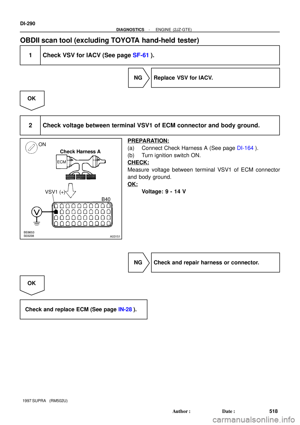
2 Check voltage between terminal VSV1 of ECM connector and body ground.
PREPARATION:
(a) Connect Check Harness A (See page DI-164).
(b) Turn ignition switch ON.
CHECK:
Measure voltage between terminal VSV1 of ECM connector
and body ground.
OK:
Voltage: 9 - 14 V
NG Check and repair harness or connector.
OK
Check and replace ECM (See page IN-28).
Page 707 of 1807
DI-292
- DIAGNOSTICSENGINE (2JZ-GTE)
520 Author�: Date�:
1997 SUPRA (RM502U)
INSPECTION PROCEDURE
TOYOTA hand-held tester
1 Connect the TOYOTA hand-held tester and check operation of VSV for waste
gate valve (See page DI-266).
OK Go to step 3.
NG
2 Check VSV for waste gate valve (See page SF-63).
NG Replace VSV for waste gate valve.
OK
3 Check for open and short in harness and connector between EFI main relay
(Marking: EFI MAIN) and ECM (See page IN-28).
NG Repair or replace harness or connector.
OK
Check and replace ECM (See page IN-28).
OBDII scan tool (excluding TOYOTA hand-held tester)
1 Check VSV for waste gate valve (See page DI-266).
NG Replace VSV for waste gate valve.
OK
Page 708 of 1807
BE6653S03237
A03152
ON
Check Harness A
ECM
VSV4 (+)B60
- DIAGNOSTICSENGINE (2JZ-GTE)
DI-293
521 Author�: Date�:
1997 SUPRA (RM502U)
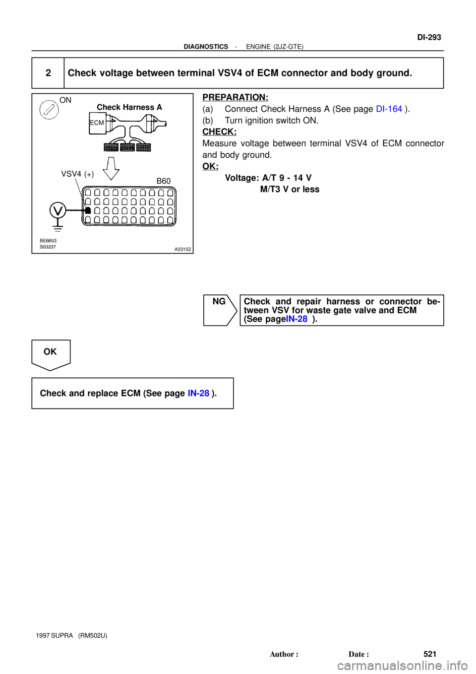
2 Check voltage between terminal VSV4 of ECM connector and body ground.
PREPARATION:
(a) Connect Check Harness A (See page DI-164).
(b) Turn ignition switch ON.
CHECK:
Measure voltage between terminal VSV4 of ECM connector
and body ground.
OK:
Voltage: A/T 9 - 14 V
M/T3 V or less
NG Check and repair harness or connector be-
tween VSV for waste gate valve and ECM
(See pageIN-28 ).
OK
Check and replace ECM (See page IN-28).
Page 710 of 1807
BE6653S03254S03255A06731
ON
Air Air
E
FE
Air Filter
VSV: ON VSV: OFF
- DIAGNOSTICSENGINE (2JZ-GTE)
DI-295
523 Author�: Date�:
1997 SUPRA (RM502U)
INSPECTION PROCEDURE
TOYOTA hand-held tester
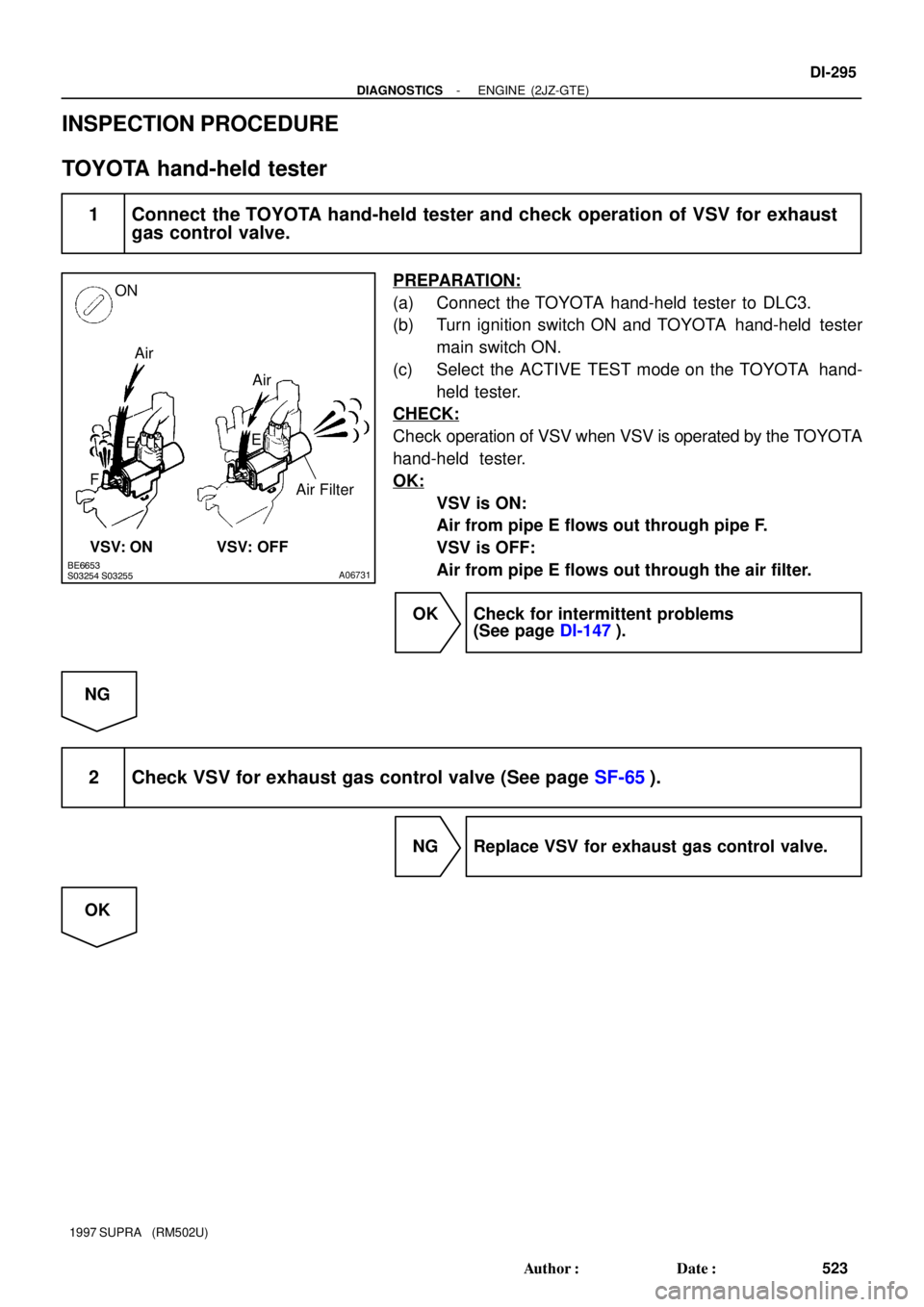
1 Connect the TOYOTA hand-held tester and check operation of VSV for exhaust
gas control valve.
PREPARATION:
(a) Connect the TOYOTA hand-held tester to DLC3.
(b) Turn ignition switch ON and TOYOTA hand-held tester
main switch ON.
(c) Select the ACTIVE TEST mode on the TOYOTA hand-
held tester.
CHECK:
Check operation of VSV when VSV is operated by the TOYOTA
hand-held tester.
OK:
VSV is ON:
Air from pipe E flows out through pipe F.
VSV is OFF:
Air from pipe E flows out through the air filter.
OK Check for intermittent problems
(See page DI-147).
NG
2 Check VSV for exhaust gas control valve (See page SF-65).
NG Replace VSV for exhaust gas control valve.
OK
Page 711 of 1807
BE6653P24633
A03153
ON
Check Harness A
ECM
B39
VSV2 (+)
DI-296
- DIAGNOSTICSENGINE (2JZ-GTE)
524 Author�: Date�:
1997 SUPRA (RM502U)
3 Check for open and short in harness and connector between EFI main relay
(Marking: EFI MAIN) and ECM (See page IN-28).
NG Repair or replace harness or connector.
OK
Check and replace ECM (See page IN-28).
OBDII scan tool (excluding TOYOTA hand-held tester)
1 Check VSV for exhaust gas control valve (See page SF-65).
NG Replace VSV for exhaust gas control valve.
OK
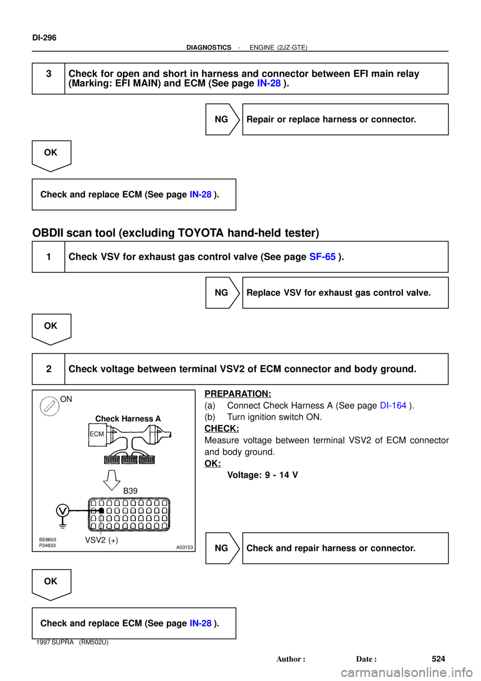
2 Check voltage between terminal VSV2 of ECM connector and body ground.
PREPARATION:
(a) Connect Check Harness A (See page DI-164).
(b) Turn ignition switch ON.
CHECK:
Measure voltage between terminal VSV2 of ECM connector
and body ground.
OK:
Voltage: 9 - 14 V
NG Check and repair harness or connector.
OK
Check and replace ECM (See page IN-28).

1 msec./Division
(Idling or IG switch ON) E")