Page 690 of 1807
- DIAGNOSTICSENGINE (2JZ-GTE)
DI-275
503 Author�: Date�:
1997 SUPRA (RM502U)
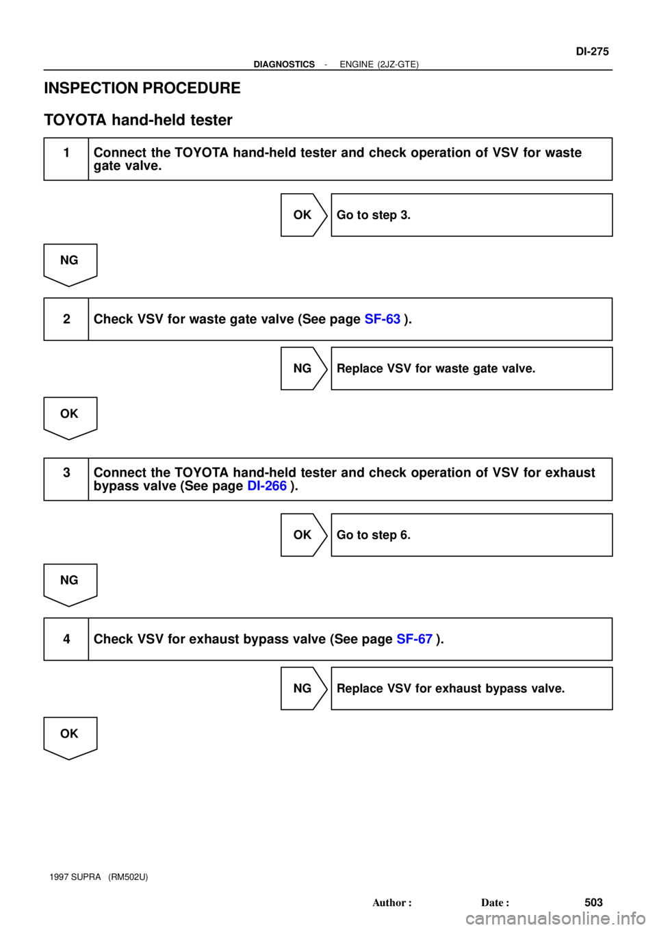
INSPECTION PROCEDURE
TOYOTA hand-held tester
1 Connect the TOYOTA hand-held tester and check operation of VSV for waste
gate valve.
OK Go to step 3.
NG
2 Check VSV for waste gate valve (See page SF-63).
NG Replace VSV for waste gate valve.
OK
3 Connect the TOYOTA hand-held tester and check operation of VSV for exhaust
bypass valve (See page DI-266).
OK Go to step 6.
NG
4 Check VSV for exhaust bypass valve (See page SF-67).
NG Replace VSV for exhaust bypass valve.
OK
Page 691 of 1807
DI-276
- DIAGNOSTICSENGINE (2JZ-GTE)
504 Author�: Date�:
1997 SUPRA (RM502U)
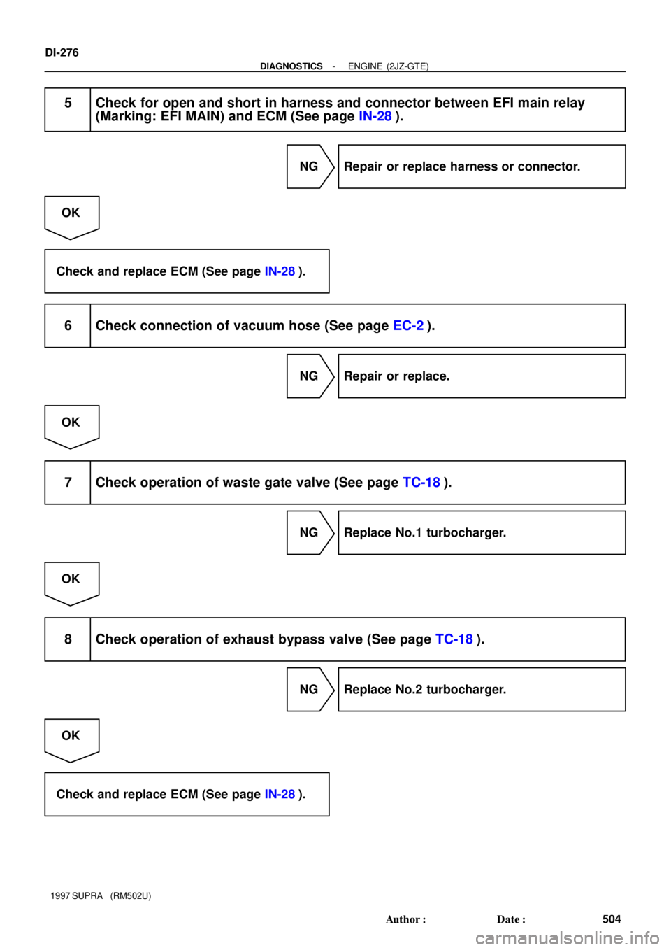
5 Check for open and short in harness and connector between EFI main relay
(Marking: EFI MAIN) and ECM (See page IN-28).
NG Repair or replace harness or connector.
OK
Check and replace ECM (See page IN-28).
6 Check connection of vacuum hose (See page EC-2).
NG Repair or replace.
OK
7 Check operation of waste gate valve (See page TC-18).
NG Replace No.1 turbocharger.
OK
8 Check operation of exhaust bypass valve (See page TC-18).
NG Replace No.2 turbocharger.
OK
Check and replace ECM (See page IN-28).
Page 692 of 1807
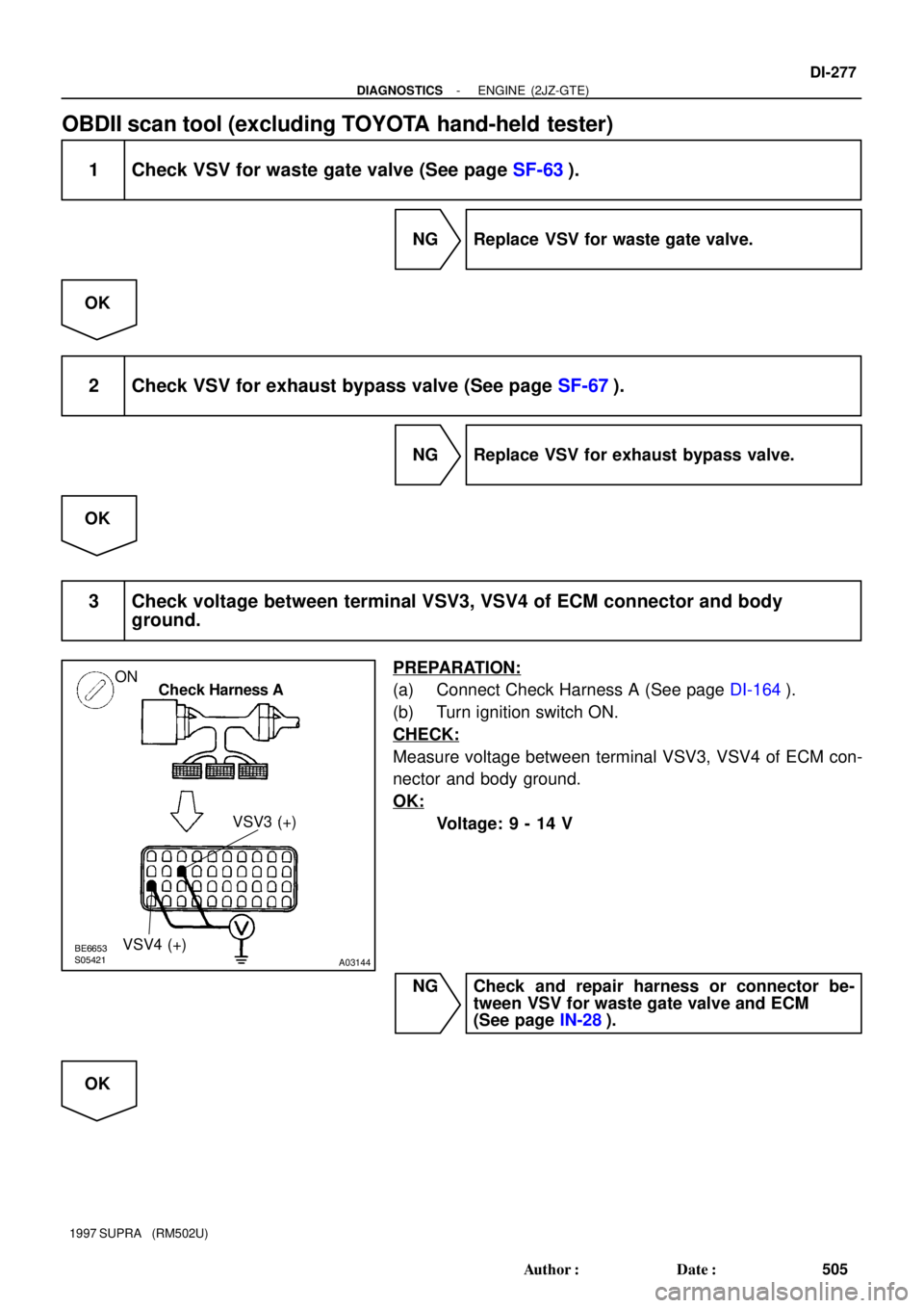
BE6653S05421
A03144
ON
Check Harness A
VSV3 (+)
VSV4 (+)
- DIAGNOSTICSENGINE (2JZ-GTE)
DI-277
505 Author�: Date�:
1997 SUPRA (RM502U)
OBDII scan tool (excluding TOYOTA hand-held tester)
1 Check VSV for waste gate valve (See page SF-63).
NG Replace VSV for waste gate valve.
OK
2 Check VSV for exhaust bypass valve (See page SF-67).
NG Replace VSV for exhaust bypass valve.
OK
3 Check voltage between terminal VSV3, VSV4 of ECM connector and body
ground.
PREPARATION:
(a) Connect Check Harness A (See page DI-164).
(b) Turn ignition switch ON.
CHECK:
Measure voltage between terminal VSV3, VSV4 of ECM con-
nector and body ground.
OK:
Voltage: 9 - 14 V
NG Check and repair harness or connector be-
tween VSV for waste gate valve and ECM
(See page IN-28).
OK
Page 693 of 1807
DI-278
- DIAGNOSTICSENGINE (2JZ-GTE)
506 Author�: Date�:
1997 SUPRA (RM502U)
4 Check connection of vacuum hose (See page EC-2).
NG Repair or replace.
OK
5 Check operation of waste gate valve (See page TC-18).
NG Replace No.1 turbocharger.
OK
6 Check operation of exhaust bypass valve (See page TC-18).
NG Replace No.2 turbocharger.
OK
Check and replace ECM (See page IN-28).
Page 695 of 1807

DI-280
- DIAGNOSTICSENGINE (2JZ-GTE)
508 Author�: Date�:
1997 SUPRA (RM502U)
INSPECTION PROCEDURE
1 Check operatio")
A00726
ON
ONBrake Pedal
DepressedBrake Pedal
Released
Check Harness A
ECM
A4
STP(+)
DI-280
- DIAGNOSTICSENGINE (2JZ-GTE)
508 Author�: Date�:
1997 SUPRA (RM502U)
INSPECTION PROCEDURE
1 Check operation of stop light.
PREPARATION:
Check if the stop lights go on and off normally when the brake
pedal is operated and released.
NG Check and repair stop light circuit.
OK
2 Check STP signal.
When using TOYOTA hand-held tester:
PREPARATION:
(a) Connect the TOYOTA hand-held tester to the DLC3.
(b) Turn the ignition switch ON and TOYOTA hand-held tes-
ter main switch ON.
CHECK:
Read the STP signal on the TOYOTA hand-held tester.
OK:
Break pedal is depressed: STP ... ON
Break pedal is released: STP ... OFF
When not using TOYOTA hand-held tester:
PREPARATION:
(a) Connect Check Harness A (See page DI-164).
(b) Turn ignition switch ON.
CHECK:
Check voltage between terminal STP of ECM and body ground.
OK:
Brake pedalVoltage
Depressed7.5 - 14 V
ReleasedBelow 1.5 V
OK Check for intermittent problems
(See page DI-147).
NG
Page 696 of 1807
- DIAGNOSTICSENGINE (2JZ-GTE)
DI-281
509 Author�: Date�:
1997 SUPRA (RM502U)
3 Check harness and connector between ECM and stop light switch
(See page IN-28).
NG Repair or replace harness or connector.
OK
Check and replace ECM.
Page 698 of 1807
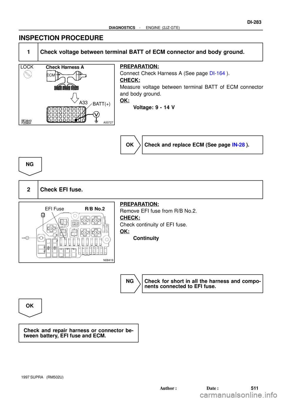
A00727
LOCK
Check Harness A
ECM
A33
BATT(+)
N08419
EFI FuseR/B No.2
- DIAGNOSTICSENGINE (2JZ-GTE)
DI-283
511 Author�: Date�:
1997 SUPRA (RM502U)
INSPECTION PROCEDURE
1 Check voltage between terminal BATT of ECM connector and body ground.
PREPARATION:
Connect Check Harness A (See page DI-164).
CHECK:
Measure voltage between terminal BATT of ECM connector
and body ground.
OK:
Voltage: 9 - 14 V
OK Check and replace ECM (See page IN-28).
NG
2 Check EFI fuse.
PREPARATION:
Remove EFI fuse from R/B No.2.
CHECK:
Check continuity of EFI fuse.
OK:
Continuity
NG Check for short in all the harness and compo-
nents connected to EFI fuse.
OK
Check and repair harness or connector be-
tween battery, EFI fuse and ECM.
Page 699 of 1807
DI-284
- DIAGNOSTICSENGINE (2JZ-GTE)
512 Author�: Date�:
1997 SUPRA (RM502U)
DTC P1605 Knock Control CPU Malfunction
CIRCUIT DESCRIPTION
Refer to Knock Sensor 1, 2 Circuit Malfunction on page DI-209.
DTC No.DTC Detecting ConditionTrouble Area
P1605Engine control computer malfunction
(for knock contorl)�ECM
WIRING DIAGRAM
Refer to page DI-209 for WIRING DIAGRAM.
INSPECTION PROCEDURE
1 Are there any other codes (besides DTC P1605) being output?
YES Go to relevant DTC chart.
NO
Check and replace ECM. (See page IN-28).
DI4TM-01