Page 713 of 1807
BE6653S03256S03257A06732
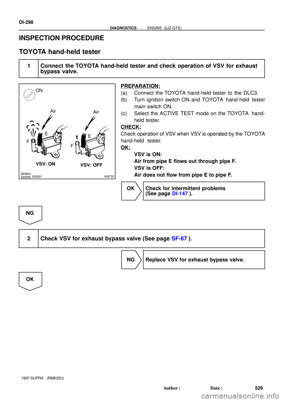
ON
Air
Air
FE
FE
VSV: ON
VSV: OFF
DI-298
- DIAGNOSTICSENGINE (2JZ-GTE)
526 Author�: Date�:
1997 SUPRA (RM502U)
INSPECTION PROCEDURE
TOYOTA hand-held tester
1 Connect the TOYOTA hand-held tester and check operation of VSV for exhaust
bypass valve.
PREPARATION:
(a) Connect the TOYOTA hand-held tester to the DLC3.
(b) Turn ignition switch ON and TOYOTA hand-held tester
main switch ON.
(c) Select the ACTIVE TEST mode on the TOYOTA hand-
held tester.
CHECK:
Check operation of VSV when VSV is operated by the TOYOTA
hand-held tester.
OK:
VSV is ON:
Air from pipe E flows out through pipe F.
VSV is OFF:
Air does not flow from pipe E to pipe F.
OK Check for intermittent problems
(See page DI-147).
NG
2 Check VSV for exhaust bypass valve (See page SF-67).
NG Replace VSV for exhaust bypass valve.
OK
Page 714 of 1807
BE6653S03239
A03154
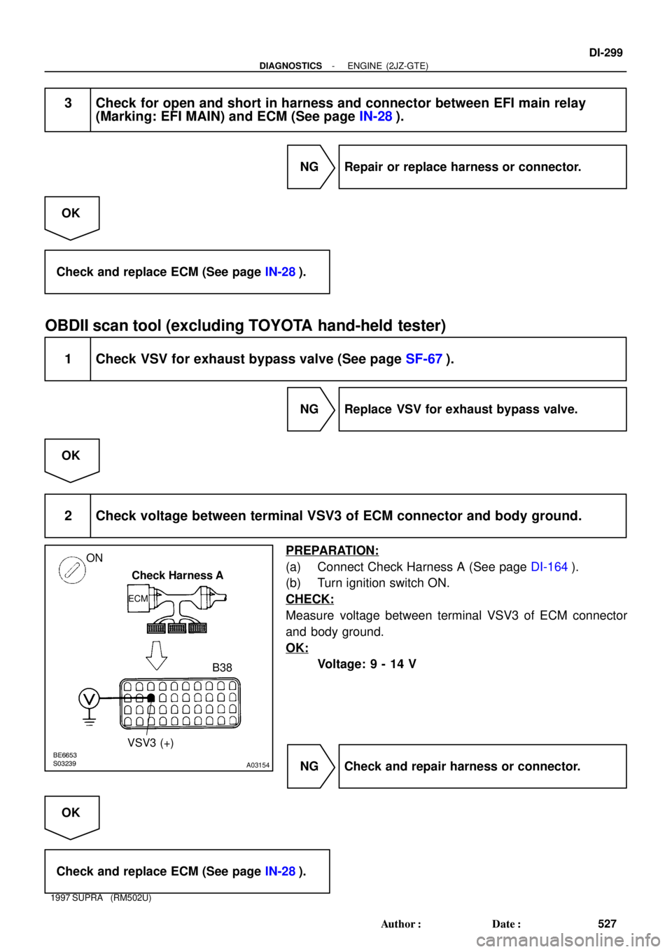
ON
Check Harness A
ECM
B38
VSV3 (+)
- DIAGNOSTICSENGINE (2JZ-GTE)
DI-299
527 Author�: Date�:
1997 SUPRA (RM502U)
3 Check for open and short in harness and connector between EFI main relay
(Marking: EFI MAIN) and ECM (See page IN-28).
NG Repair or replace harness or connector.
OK
Check and replace ECM (See page IN-28).
OBDII scan tool (excluding TOYOTA hand-held tester)
1 Check VSV for exhaust bypass valve (See page SF-67).
NG Replace VSV for exhaust bypass valve.
OK
2 Check voltage between terminal VSV3 of ECM connector and body ground.
PREPARATION:
(a) Connect Check Harness A (See page DI-164).
(b) Turn ignition switch ON.
CHECK:
Measure voltage between terminal VSV3 of ECM connector
and body ground.
OK:
Voltage: 9 - 14 V
NG Check and repair harness or connector.
OK
Check and replace ECM (See page IN-28).
Page 717 of 1807
DI-302
- DIAGNOSTICSENGINE (2JZ-GTE)
530 Author�: Date�:
1997 SUPRA (RM502U)
INSPECTION PROCEDURE
HINT:
This diagnostic chart is based on the premise that the engine is cranked normally. If the engine is not
cranked, proceed to the matrix chart of problem symptoms on page DI-169.
TOYOTA hand-held tester
1 Connect the TOYOTA hand-held tester and check STA signal.
PREPARATION:
(a) Connect the TOYOTA hand-held tester to the DLC3.
(b) Turn ignition switch ON and push TOYOTA hand-held tester main switch ON.
CHECK:
Read STA signal on the TOYOTA hand-held tester while starter operates.
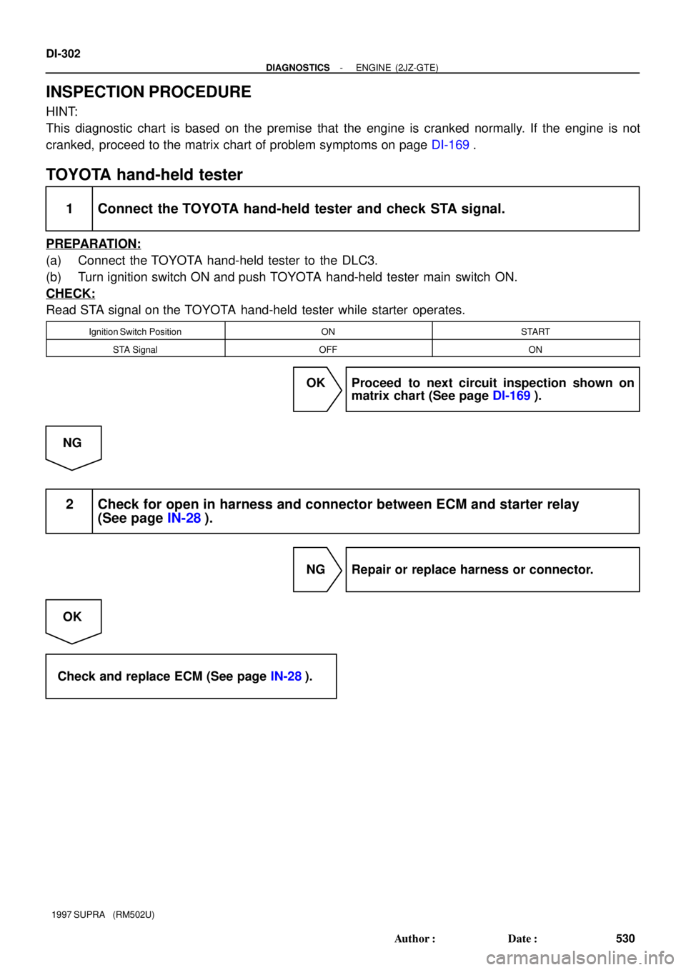
Ignition Switch PositionONSTART
STA SignalOFFON
OK Proceed to next circuit inspection shown on
matrix chart (See page DI-169).
NG
2 Check for open in harness and connector between ECM and starter relay
(See page IN-28).
NG Repair or replace harness or connector.
OK
Check and replace ECM (See page IN-28).
Page 718 of 1807
S04081BE6653A03406
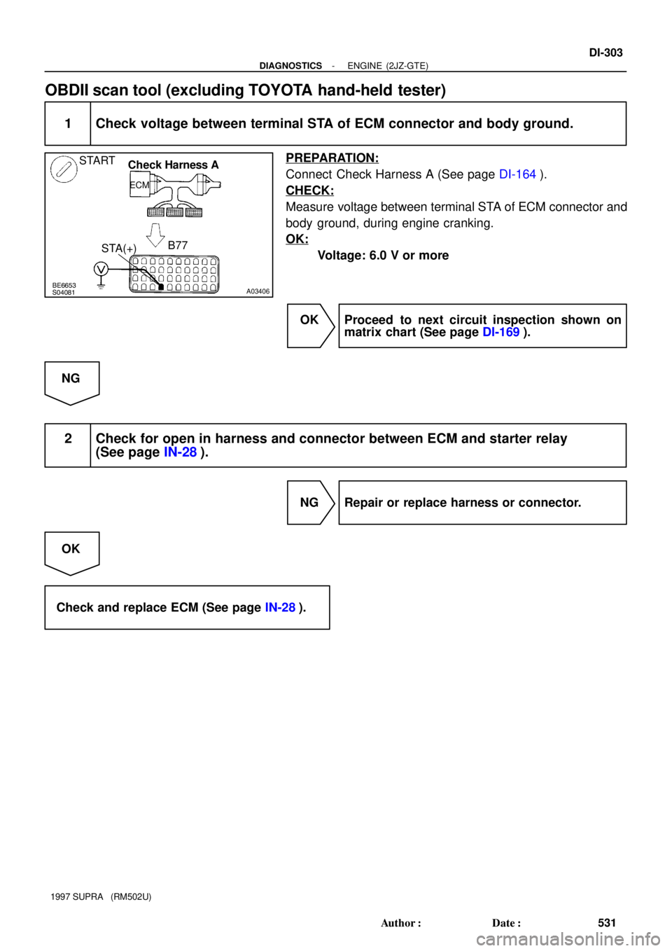
START
Check Harness A
ECM
B77
STA(+)
- DIAGNOSTICSENGINE (2JZ-GTE)
DI-303
531 Author�: Date�:
1997 SUPRA (RM502U)
OBDII scan tool (excluding TOYOTA hand-held tester)
1 Check voltage between terminal STA of ECM connector and body ground.
PREPARATION:
Connect Check Harness A (See page DI-164).
CHECK:
Measure voltage between terminal STA of ECM connector and
body ground, during engine cranking.
OK:
Voltage: 6.0 V or more
OK Proceed to next circuit inspection shown on
matrix chart (See page DI-169).
NG
2 Check for open in harness and connector between ECM and starter relay
(See page IN-28).
NG Repair or replace harness or connector.
OK
Check and replace ECM (See page IN-28).
Page 720 of 1807
A00729
ON
Check Harness A
ECM
A31
+B
B69
E1(-)
- DIAGNOSTICSENGINE (2JZ-GTE)
DI-305
533 Author�: Date�:
1997 SUPRA (RM502U)
INSPECTION PROCEDURE
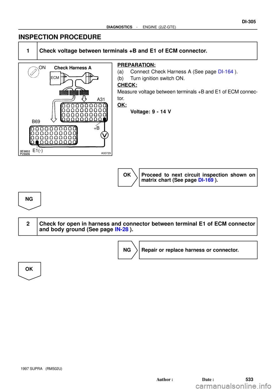
1 Check voltage between terminals +B and E1 of ECM connector.
PREPARATION:
(a) Connect Check Harness A (See page DI-164).
(b) Turn ignition switch ON.
CHECK:
Measure voltage between terminals +B and E1 of ECM connec-
tor.
OK:
Voltage: 9 - 14 V
OK Proceed to next circuit inspection shown on
matrix chart (See page DI-169).
NG
2 Check for open in harness and connector between terminal E1 of ECM connector
and body ground (See page IN-28).
NG Repair or replace harness or connector.
OK
Page 721 of 1807
A00730
ONCheck Harness A
ECM
A1
IGSW(+)
N08417
J/B No.1
IGN Fuse
DI-306
- DIAGNOSTICSENGINE (2JZ-GTE)
534 Author�: Date�:
1997 SUPRA (RM502U)
3 Check voltage between terminal IGSW of ECM connector and body ground.
PREPARATION:
Turn ignition switch ON.
CHECK:
Measure voltage between terminal IGSW of ECM and body
ground.
OK:
Voltage: 9 - 14 V
OK Go to step 6.
NG
4 Check IGN fuse.
PREPARATION:
Remove IGN fuse from J/B No.1.
CHECK:
Check continuity of IGN fuse.
OK:
Continuity
NG Check for short in all the harness and compo-
nents connected to IGN fuse.
OK
Page 722 of 1807
A00731
ONCheck Harness A
ECM
A24 M-REL (+)
- DIAGNOSTICSENGINE (2JZ-GTE)
DI-307
535 Author�: Date�:
1997 SUPRA (RM502U)
5 Check ignition switch (See page BE-13).
NG Replace ignition switch.
OK
Check for open and short in harness and connector between battery and ignition switch, ignition
switch and ECM (See page IN-28).
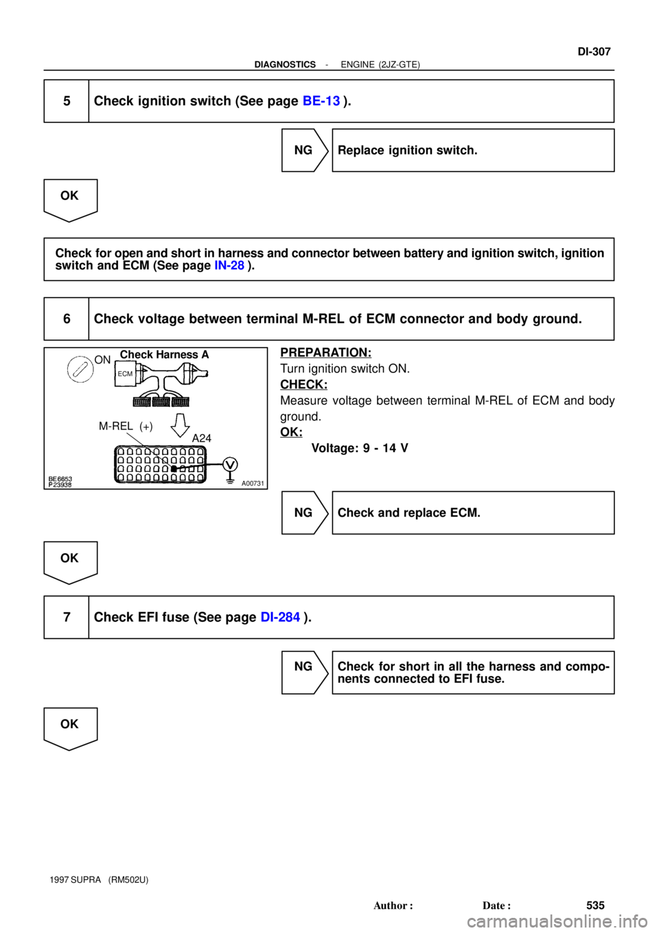
6 Check voltage between terminal M-REL of ECM connector and body ground.
PREPARATION:
Turn ignition switch ON.
CHECK:
Measure voltage between terminal M-REL of ECM and body
ground.
OK:
Voltage: 9 - 14 V
NG Check and replace ECM.
OK
7 Check EFI fuse (See page DI-284).
NG Check for short in all the harness and compo-
nents connected to EFI fuse.
OK
Page 723 of 1807
DI-308
- DIAGNOSTICSENGINE (2JZ-GTE)
536 Author�: Date�:
1997 SUPRA (RM502U)
8 Check EFI main relay (Marking: EFI MAIN) (See page SF-54).
NG Replace EFI main relay (Marking: EFI MAIN).
OK
9 Check for open and short in harness and connector between terminal M-REL of
ECM connector and body ground (See page IN-28).
NG Repair or replace harness or connector.
OK
Check for open and short in harness and connector between terminal +B of ECM connector and
battery (See page IN-28).