Page 118 of 1807
CH0086
CorrectWrong
AC0Q3-01
P10652
Type A
AB
Type B
- AIR CONDITIONINGDRIVE BELT
AC-15
2163 Author�: Date�:
1997 SUPRA (RM502U)
DRIVE BELT
ON-VEHICLE INSPECTION
1. INSPECT DRIVE BELT'S INSTALLATION CONDITION
Check that the drive belt fits properly in the ribbed grooves.
2. INSPECT DRIVE BELT TENTION
Check that the tension is within A range on the auto tensioner
scale.
If the tension is not within the A range on the scale, replace the
belt with a new one.
HINT:
When replacing the drive belt with a new one, the belt tension
should be within the B range on the belt tensioner scale.
Page 119 of 1807
AC0Q4-01
P14738
Turn AC-16
- AIR CONDITIONINGDRIVE BELT
2164 Author�: Date�:
1997 SUPRA (RM502U)
REMOVAL
REMOVE DRIVE BELT
Loosen the drive belt tension by turning the drive belt tensioner
clockwise, and remove the drive belt.
Page 129 of 1807
AC2SS-01
I03512
I03512
Drive Belt
Power Steering
Pump Bracket
Engine Under CoverDischarge Hose Power Steering
Pump
Compressor Stator
Rotor
Shim Pressure Plate
Suction Hose
Compressor
� Snap Ring
� Snap Ring
� Non-reusable part AC-32
- AIR CONDITIONINGCOMPRESSOR AND MAGNETIC CLUTCH
2180 Author�: Date�:
1997 SUPRA (RM502U)
COMPONENTS
Page 130 of 1807
AC0QI-01
I03524
N08004
N08005
- AIR CONDITIONINGCOMPRESSOR AND MAGNETIC CLUTCH
AC-33
2181 Author�: Date�:
1997 SUPRA (RM502U)
REMOVAL
1. RUN ENGINE AT IDLE SPEED WITH A/C ON FOR
APPROX. 10 MINUTES
2. STOP ENGINE
3. DISCONNECT NEGATIVE (- ) TERMINAL CABLE
FROM BATTERY
4. DISCHARGE REFRIGERANT FROM REFRIGERATION
SYSTEM
5. REMOVE ENGINE UNDER COVER
6. REMOVE DRIVE BELT
(See page AC-16)
7. DISCONNECT DISCHARGE AND SUCTION HOSES
FROM COMPRESSOR
Remove the 2 nuts and disconnect the both hoses.
NOTICE:
Cap the open fittings immediately to keep moisture or dirt
out of the system.
8. REMOVE COMPRESSOR
(a) Disconnect the connector.
(b) Remove the 4 bolts and nut.
(c) Using a tory socket (E10), remove the stud bolt and com-
pressor.
Page 134 of 1807
AC0QL-01
AC-38
- AIR CONDITIONINGCOMPRESSOR AND MAGNETIC CLUTCH
2186 Author�: Date�:
1997 SUPRA (RM502U)
INSTALLATION
1. INSTALL COMPRESSOR
(a) Install the stud bolt.
Torque: 26 N´m (265 kgf´cm, 19.2 ft´lbf)
(b) Install the compressor with 4 bolts and nut.
Torque: 52 N´m (530 kgf´cm, 38.3 ft´lbf)
(c) Connect the magnetic clutch connector.
(d) Install the engine under cover.
2. CONNECT DISCHARGE AND SUCTION HOSES
Connect the both hoses with 2 bolts.
Torque: 10 N´m (100 kgf´cm, 7 ft´lbf)
NOTICE:
Hose should be connected immediately after the caps have been removed.
HINT:
Lublicate 2 new O-rings with compressor oil and install the hoses.
3. INSTALL POWER STEERING PUMP SET BOLTS
Torque: 58 N´m (590 kgf´cm, 42 ft´lbf)
4. INSTALL DRIVE BELT
(See page AC-17)
5. CONNECT NEGATIVE (-) TERMINAL CABLE TO BATTERY
6. EVACUATE AIR IN REFRIGERATION SYSTEM AND CHARGE EITH REFRIGERANT
Specified amount: 700 ± 50 g (24.96 ± 1.76 oz.)
7. INSPECT FOR LEAKAGE OF REFRIGERANT
Using a gas leak detecter, check for leakage of refrigerant.
If there is leakage, check the tightening torque at the joints.
8. INSPECT A/C OPERATION
Page 163 of 1807
- BODY ELECTRICALBODY ELECTRICAL SYSTEM
BE-7
1985 Author�: Date�:
1997 SUPRA (RM502U)
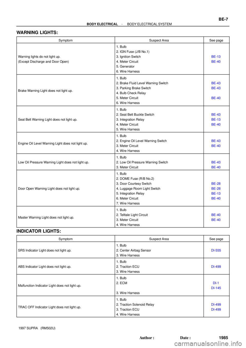
WARNING LIGHTS:
SymptomSuspect AreaSee page
Warning lights do not light up.
(Except Discharge and Door Open)
1. Bulb
2. IGN Fuse (J/B No.1)
3. Ignition Switch
4. Meter Circuit
5. Generator
6. Wire Harness
BE-13
BE-40
Brake Warning Light does not light up.
1. Bulb
2. Brake Fluid Level Warning Switch
3. Parking Brake Switch
4. Bulb Check Relay
5. Meter Circuit
6. Wire Harness
BE-43
BE-43
BE-40
Seat Belt Warning Light does not light up.
1. Bulb
2. Seat Belt Buckle Switch
3. Integration Relay
4. Meter Circuit
5. Wire Harness
BE-43
BE-13
BE-40
Engine Oil Level Warning Light does not light up.
1. Bulb
2. Engine Oil Level Warning Switch
3. Meter Circuit
4. Wire Harness
BE-43
BE-40
Low Oil Pressure Warning Light does not light up.
1. Bulb
2. Low Oil Pressure Warning Switch
3. Meter Circuit
BE-43
BE-40
Door Open Warning Light does not light up.
1. Bulb
2. DOME Fuse (R/B No.2)
3. Door Courtesy Switch
4. Luggage Room Light Switch
5. Integration Relay
6. Meter Circuit
7. Wire Harness
BE-28
BE-28
BE-13
BE-40
Master Warning Light does not light up.
1. Bulb
2. Telltale Light Circuit
3. Meter Circuit
4. Wire Harness
BE-40
BE-40
INDICATOR LIGHTS:
SymptomSuspect AreaSee page
SRS Indicator Light does not light up.
1. Bulb
2. Center Airbag Sensor
3. Wire Harness
DI-555
ABS Indicator Light does not light up.
1. Bulb
2. Traction ECU
3. Wire Harness
DI-499
Malfunction Indicator Light does not light up.
1. Bulb
2. ECM
3. Wire Harness
DI-1
DI-145
TRAC OFF Indicator Light does not light up.
1. Bulb
2. Traction Solenoid Relay
3. Traction ECU
4. Wire Harness
DI-499
DI-499
Page 198 of 1807

I02082I02081
I02080
I02079
I05022
Security Indicator
TRAC OFF Indicator
Low Oil Pressure Warning
Engine Oil Level Warning
Malfunction Indicator
ABS Indicator
No.
Combination Meter (Terminal B2)
ECM
ECM
Low Oil Pressure Warning Switch
Combination Meter (Terminal B4)
TRAC ECU, Traction Solenoid Relay
Ground
Theft Deterrent and Door Lock ECUWire Harness Side
1
2
3
4
5
6
8
9
10
No.Wire Harness Side
GAUGE Fuse
ECU-B Fuse
IGN Fuse
PANEL Fuse
Vehicle Speed Sensor (Terminal 3)
Ground
DOME Fuse
Light Control Rheostat
Combination Meter (Terminal B1)
Generator Terminal
Door Courtesy Switch
Integration Relay (Terminal 9)
Light Failure Sensor Center Airbag Sensor 1
2
3
4
5
6
8
107
11
12
14
15
16
18GAUGE Fuse
PPS ECU, Cruise Control ECU, ECM OD/TRIP
Meter
Open Door Warning
Seat Belt Warning
SRS Warning 8
6 5
3
4
110
2 9
7
10
5
14
18
12
16
15
114
6
1
8
3
2Air Conditioning Amplifier Telltale Light LH:
Telltale Light RH:
Rear Light Warning
Discharge Warning BE-42
- BODY ELECTRICALCOMBINATION METER
2020 Author�: Date�:
1997 SUPRA (RM502U)
2. TELLTALE LIGHT:
Page 207 of 1807

N08953
N08954
BE6219
Junction Block Side
Connector ºAº
- BODY ELECTRICALCOMBINATION METER
BE-51
2029 Author�: Date�:
1997 SUPRA (RM502U)
26. INSPECT INTEGRATION RELAY OPERATION
(a) Connect the positive (+) lead from the battery to terminals
1 and 7.
(b) Connect the positive (+) lead from the battery to terminal
9 through a 3.4 W test bulb.
(c) Check that the test bulb lights up and buzzer sounds for
4 - 8 seconds when the negative (-) lead from the battery
is connected to terminal 10.
(d) Check that the buzzer sounding in (c) stops when the
negative (-) lead from the battery is connected to terminl
8.
If operation is not as specified, replace the integration relay.
27. INSPECT RELAY CIRCUIT
Remove the relay from the junction block No. 1 and inspect the
connectors on the junction block side.
Tester connectionConditionSpecified condition
4 - GroundDriver's door openContinuity
4 - GroundDriver's door closeNo continuity
5 - GroundIgnition key SetContinuity
5 - GroundIgnition key removeNo continuity
8 - GroundDriver's seat belt fastenContinuity
8 - GroundDriver's seat belt unfastenNo continuity
10 - GroundConstantContinuity
1 - GroundConstantBattery positive voltage
9 - GroundIgnition switch position ONBattery positive voltage
9 - GroundIgnition switch position LOCK or ACCNo Voltage
If circuit is not as specified, tray replacing the relay with a new
one.