Page 1574 of 1807
Z16580
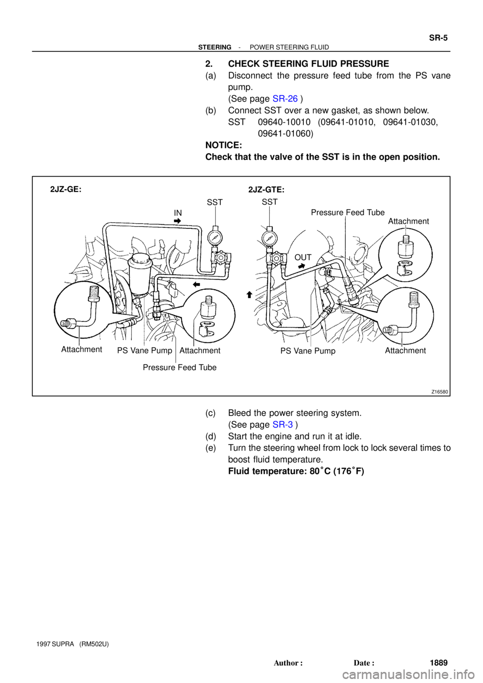
INSSTSST
OUTPressure Feed Tube
Attachment
PS Vane Pump 2JZ-GE:
2JZ-GTE:
Attachment Attachment PS Vane Pump Attachment
Pressure Feed Tube
- STEERINGPOWER STEERING FLUID
SR-5
1889 Author�: Date�:
1997 SUPRA (RM502U)
2. CHECK STEERING FLUID PRESSURE
(a) Disconnect the pressure feed tube from the PS vane
pump.
(See page SR-26)
(b) Connect SST over a new gasket, as shown below.
SST 09640-10010 (09641-01010, 09641-01030,
09641-01060)
NOTICE:
Check that the valve of the SST is in the open position.
(c) Bleed the power steering system.
(See page SR-3)
(d) Start the engine and run it at idle.
(e) Turn the steering wheel from lock to lock several times to
boost fluid temperature.
Fluid temperature: 80°C (176°F)
Page 1576 of 1807
Z13450
2JZ-GE:
2JZ-GTE:SR0CK-01
- STEERINGAIR CONTROL VALVE
SR-7
1891 Author�: Date�:
1997 SUPRA (RM502U)
AIR CONTROL VALVE
INSPECTION
CHECK IDLE-UP
(a) Turn the air conditioner switch off.
(b) Start the engine and run it at idle.
(c) Fully turn the steering wheel.
(d) Check that the engine speed decreases when the vacu-
um hose of the air control valve is pinched.
(e) Check that the engine speed increases when the hose is
released.
Page 1577 of 1807

STEERING WHEEL
INSPECTION
1. CHECK STEERING WHEEL FREEPLAY
With the vehicle stopp")
SR13W-01
R09732
W00625
PPS Solenoid
Connector SR-8
- STEERINGSTEERING WHEEL
1892 Author�: Date�:
1997 SUPRA (RM502U)
STEERING WHEEL
INSPECTION
1. CHECK STEERING WHEEL FREEPLAY
With the vehicle stopped and tires pointed straight ahead, rock
the steering wheel gently back and forth with light finger pres-
sure.
Freeplay should not exceed the maximum.
Maximum freeplay: 30 mm (1.18 in.)
2. CHECK STEERING EFFORT
(a) Center the steering wheel.
(b) Remove the steering wheel pad.
(See page SR-1 1)
(c) Start the engine and run it at idle.
(d) Measure the steering effort in both directions.
Reference (Maximum): 6.9 N´m (70 kgf´cm, 61 in.´lbf)
If steering effort is excessive, repair the power steering unit.
HINT:
Be sure to consider the tire type, pressure and contact surface
before making your diagnosis.
(e) Disconnect the PPS solenoid connector.
(f) Measure the steering effort in both directions and check
that the steering effort exceeds the reference value in (d),
and that the power assist is operating.
If steering effort is not heavier than (d), check the solenoid.
(g) Connect the connector.
(h) Torque the steering wheel set nut.
Torque: 35 N´m (360 kgf´cm, 26 ft´lbf)
(i) Install the steering wheel pad.
(See page SR-21)
Page 1621 of 1807

INSTALLATION
1. INSTALL PS GEAR ASSEMBLY
(a) Temporarily install the 2 bolts and nuts.
(b) After installing the")
SR14E-01
SR-52
- STEERINGPOWER STEERING GEAR
1936 Author�: Date�:
1997 SUPRA (RM502U)
INSTALLATION
1. INSTALL PS GEAR ASSEMBLY
(a) Temporarily install the 2 bolts and nuts.
(b) After installing the rack housing bracket and grommet, torque the 2 bolts and nuts.
Torque: 75 N´m (770 kgf´cm, 55 ft´lbf)
2. INSTALL RACK HOUSING BRACKET AND GROMMET
Torque the 2 bolts and nuts.
Torque: 75 N´m (770 kgf´cm, 55 ft´lbf)
3. CONNECT PPS SOLENOID CONNECTOR
4. CONNECT PRESSURE FEED TUBE
Torque the union bolt over a new gasket.
Torque: 49 N´m (500 kgf´cm, 36 ft´lbf)
5. CONNECT RETURN TUBE
Torque the union bolt over 2 new gaskets.
Torque: 49 N´m (500 kgf´cm, 36 ft´lbf)
6. CONNECT RH AND LH TIE ROD ENDS (See page SA-17)
7. CONNECT INTERMEDIATE SHAFT (See page SR-21)
8. INSTALL FR SUSPENSION MEMBER PROTECTOR
Tighten the 4 bolts.
9. INSTALL ENGINE UNDER COVER
Install the 10 bolts.
10. POSITION FRONT WHEELS FACING STRAIGHT AHEAD
HINT:
Do it with the front of the vehicle jacked up.
11. CENTER SPIRAL CABLE (See page SR-21)
12. INSTALL STEERING WHEEL
(a) Align the matchmarks on the wheel and steering column main shaft.
(b) Temporarily tighten the wheel set nut.
(c) Connect the connector.
13. BLEED POWER STEERING SYSTEM (See page SR-3)
14. CHECK STEERING WHEEL CENTER POINT
15. TORQUE STEERING WHEEL SET NUT
Torque: 35 N´m (360 kgf´cm, 26 ft´lbf)
16. INSTALL STEERING WHEEL PAD (See page SR-21)
17. CHECK FRONT WHEEL ALIGNMENT (See page SA-2)
Page 1624 of 1807

62
- STEERINGPROGRESSIVE POWER STEERING (PPS)
SR-55
1939 Author�: Date�:
1997 SUPRA (RM502U)
(e) Inspect the PPS solenoid valve circuit.
(")
F03098
Wire Harness Side:
R07587
62
R07587
37 mph (60 km/h)
62
- STEERINGPROGRESSIVE POWER STEERING (PPS)
SR-55
1939 Author�: Date�:
1997 SUPRA (RM502U)
(e) Inspect the PPS solenoid valve circuit.
(1) Disconnect the PPS ECU connector.
(2) Check continuity between the terminals of the con-
nector on wire harness side, as shown in the illustra-
tion.
Tester connectionSpecified condition
1 - 6No continuity
2 - 6No continuity
If it is not as specified, repair or replace wire harness or connec-
tor.
(3) Connect the PPS ECU connector.
4. INSPECT PPS ECU
(a) Jack up the vehicle and support it on stands.
(b) Start the engine.
(c) Measure the voltage of ECU.
(1) Using a voltmeter, measure the voltage between
ECU terminals 2 and 6 while the engine is idling.
Standard voltage: 0.15 - 0.20 V
(2) Place the transmission in gear and while running at
about 62 mph (100 km/h), measure the voltage be-
tween ECU terminals 2 and 6.
Standard voltage:
2JZ-GE: 0.06 - 0.17 v
2JZ-GTE: 0.07 - 0.17 v
If no voltage, try another ECU for SUPRA.
(d) Lower the vehicle.
Page 1784 of 1807

(Check Procedure and Correction Method)
Check intake air system, and repair or replace parts
as necessary. (See page TC-5)
Check intake air system, and repair or replace part")
TC037-01
(Possible Cause)
(Check Procedure and Correction Method)
Check intake air system, and repair or replace parts
as necessary. (See page TC-5)
Check intake air system, and repair or replace parts
as necessary. (See page TC-5)
Check exhaust system, and repair or replace parts
as necessary. (See page TC-5)
Check exhaust system, and repair or replace parts
as necessary. (See page TC-5) Check turbocharging pressure. (See page TC-5)
Turbocharging pressure:
61 - 75 kPa
(0.62 - 0.76 kgf/cm2, 8.8 - 10.8 psi)
If the pressure is below specifications, begin
diagnosis from item 2.
Check rotation of turbine shaft. If it does not turn or
turns with a heavy drag, replace the turbocharger
assembly.
Check axial and radial play of turbine shaft.
(See page TC-18)
Maximum axial play : 0.110 mm (0.0045 in.)
Maximum radial play: 0.173 mm (0.0068 in.)
If the play is greater than maximum, replace the
turbocharger assembly.
3. LEAK IN INTAKE AIR SYSTEM
4. RESTRICTED EXHAUST SYSTEM
6. ERRATIC TURBOCHARGER 5. LEAK IN EXHAUST SYSTEM
OPERATION 1. TURBOCHARGING PRESSURE
TOO LOW
2. RESTRICTED INTAKE SYSTEM
- TURBOCHARGING (2JZ-GTE)TROUBLESHOOTING
TC-1
1201 Author�: Date�:
1997 SUPRA (RM502U)
TROUBLESHOOTING
PROBLEM SYMPTOMS TABLE
HINT:
Before troubleshooting the turbocharger, first check the engine itself. (Valve clearance, engine compression,
ignition timing etc.)
1. INSUFFICIENT ACCELERATION, LACK OF POWER OR EXCESSIVE FUEL CONSUMPTION
Page 1786 of 1807
TURBOCHARGER
TC-3
1203 Author�: Date�:
1997 SUPRA (RM502U)
TURBOCHARGER
PRECAUTION
1. DO NOT STOP ENGINE IMMEDIATELY AFTER PUL")
TC00A-01
P11285
NO!
P13207
NO!
Ceramic
P11284
- TURBOCHARGING (2JZ-GTE)TURBOCHARGER
TC-3
1203 Author�: Date�:
1997 SUPRA (RM502U)
TURBOCHARGER
PRECAUTION
1. DO NOT STOP ENGINE IMMEDIATELY AFTER PULL-
ING A TRAILER OR AFTER HIGH SPEED OR UPHILL
DRIVING. IDLE ENGINE FOR 20 - 120 SECONDS, DE-
PENDING ON HOW HARD VEHICLE HAS BEEN DRIV-
EN
2. AVOID SUDDEN ACCELERATION OR RACING IM-
MEDIATELY AFTER STARTING A COLD ENGINE
3. DO NOT RUN ENGINE WITH AIR CLEANER RE-
MOVED, AS THIS MAY CAUSE FOREIGN MATERIAL
TO ENTER AND DAMAGE IMPELLER WHEEL OPER-
ATING AT HIGH SPEED
4. IF A TURBOCHARGER IS FOUND TO BE DEFECTIVE
AND MUST BE REPLACED, CHECK FOR CAUSE, AND
REPAIR OR REPLACE FOLLOWING ITEMS AS NEC-
ESSARY
�Engine oil level and quality
�Conditions under which the turbocharger was used
�Oil lines leading to the turbocharger
5. USE CAUTION WHEN REMOVING AND REINSTAL-
LING TURBOCHARGER ASSEMBLY. DO NOT DROP
IT OR KNOCK IT AGAINST ANYTHING OR GRASP IT
BY EASILY-DEFORMED PARTS, SUCH AS ACTUA-
TOR OR ROD, WHEN MOVING IT
6. USE CAUTION WHEN REMOVING AND REINSTAL-
LING EXHAUST GAS CONTROL VALVE ASSEMBLY.
DO NOT DROP IT OR KNOCK IT AGAINST ANYTHING
OR GRASP IT BY EASILY-DEFORMED PARTS, SUCH
AS ACTUATOR OR ROD, WHEN MOVING IT. CON-
TROL VALVE IS CERAMIC
7. BEFORE REMOVING TURBOCHARGER, PLUG IN-
TAKE AND EXHAUST PORTS AND OIL INLET TO PRE-
VENT ENTRY OF DIRT OR OTHER FOREIGN MATERI-
AL
8. IF REPLACING TURBOCHARGER, CHECK FOR AC-
CUMULATION OF SLUDGE PARTICLES IN OIL PIPES,
AND IF NECESSARY, REPLACE OIL PIPES
9. COMPLETELY REMOVE GASKET ADHERED TO LU-
BRICATION OIL PIPE FLANGE AND TURBOCHAR-
GER OIL FLANGE
10. WHEN REPLACING BOLT OR NUTS, USE ONLY AU-
THORIZED REPLACEMENT PARTS TO PREVENT
BREAKAGE OR DEFORMATION
Page 1788 of 1807
TURBOCHARGER
TC-5
1205 Author�: Date�:
1997 SUPRA (RM502U)
ON-VEHICLE INSPECTION
1. INSPECT INTAKE AIR SYST")
TC00C-01
P13205
Disconnect
Move49 kpa
SST
P12024
61 - 75 kpa
SST
- TURBOCHARGING (2JZ-GTE)TURBOCHARGER
TC-5
1205 Author�: Date�:
1997 SUPRA (RM502U)
ON-VEHICLE INSPECTION
1. INSPECT INTAKE AIR SYSTEM
Check for leakage or clogging between the air cleaner and
turbocharger inlet and between the turbocharger outlet and cyl-
inder head.
�Clogged air cleaner ..Clean or replace air filter
�Hoses collapsed or deformed .... Repair or replace
�Leakage from connections .... Check each
connection and repair
�Cracks in components .... Check and replace
2. INSPECT EXHAUST SYSTEM
Check for leakage or clogging between the cylinder head and
turbocharger inlet and between the turbocharger outlet and ex-
haust pipe.
�Deformed components .... Repair or replace
�Foreign material in passages .... Remove
�Leakage from components .... Repair or replace
�Cracks in components .... Check and replace
3. INSPECT EXHAUST GAS CONTROL
VALVE OPERATION
(a) Disconnect the air hose from the actuator.
(b) Using SST, apply approx. 49 kPa (0.50 kgf/cm
2, 7.1 psi)
of pressure to the actuator.
SST 09992-00242
(c) Check that the actuator push rod moves.
(d) Reconnect the air hose to the actuator.
If operation is not as specified, replace the control valve assem-
bly.
4. INSPECT TURBOCHARGING PRESSURE
(a) Using a 3-way connector, connect SST (turbocharger
pressure gauge) to the hose between the gas filter and
turbo pressure sensor.
SST 09992-00242
(b) While driving with the engine running at 5,600 rpm or
more with the throttle valve fully open in the 1st gear/L
range, check the turbocharging pressure.
Standard pressure:
61 - 75 kPa (0.62 - 0.76 kgf/cm
2, 8.8 - 10.8 psi)
If the pressure is less than that specified, check the intake and
exhaust systems for leakage. If there is no leakage, replace the
turbocharger assembly.
If the pressure is above specification, check if the actuator hose
is disconnected or cracked. If not, replace the turbocharger as-
sembly.