Page 1506 of 1807
SF0HD-01
P11386Connector
P11418(1)(2)
(3)
P12820
Check Valve
Seal
Washer
- SFI (2JZ-GTE)IDLE AIR CONTROL (IAC) VALVE
SF-51
1377 Author�: Date�:
1997 SUPRA (RM502U)
REMOVAL
1. DRAIN ENGINE COOLANT
2. DISCONNECT IAC VALVE CONNECTOR
3. REMOVE IAC VALVE
(a) Remove the 2 bolts, and disconnect the IAC valve from
the air intake chamber.
(b) Remove the gasket
.
(c) Disconnect these hoses from the IAC valve, and remove
the IAC valve:
(1) Air hose
(2) Water bypass hose (from No.2 water bypass pipe)
(3) Water bypass hose (from No.4 water bypass pipe)
(d) Remove the seal washer and check valve.
Page 1508 of 1807
SF0HF-01
P11387
Check Valve
Seal
WasherInside
- SFI (2JZ-GTE)IDLE AIR CONTROL (IAC) VALVE
SF-53
1379 Author�: Date�:
1997 SUPRA (RM502U)
INSTALLATION
1. INSTALL IAC VALVE
(a) Install the check valve and seal washer.
NOTICE:
Be careful of the check valve and seal washer installation
direction.
(b) Connect these hoses:
�Air hose
�Water bypass hose (from No.2 water bypass
pipe)
�Water bypass hose (from No.4 water bypass
pipe)
(c) Install a new gasket and the IAC valve with the 2 bolts.
Torque: 21 N´m (210 kgf´cm, 15 ft´lbf)
2. CONNECT IAC VALVE CONNECTOR
3. FILL WITH ENGINE COOLANT
Page 1541 of 1807
SF0IC-02
Q08242
TOYOTA Hand-Held Tester
DLC3
P11358Sound Scope
- SFI (2JZ-GTE)FUEL CUT RPM
SF-87
1413 Author�: Date�:
1997 SUPRA (RM502U)
FUEL CUT RPM
INSPECTION
1. WARM UP ENGINE
Allow the engine to warm up to normal operating temperature.
2. CONNECT TOYOTA HAND-HELD TESTER OR
OBDII SCAN TOOL
(a) Connect the TOYOTA hand-held tester or OBDII scan
tool to the DLC3.
(b) Please refer to the TOYOTA hand-held tester or
OBDII scan tool operator's manual for further details.
3. INSPECT FUEL CUTOFF OPERATION
(a) Increase the engine speed to at least 3,000 rpm.
(b) Check for injector operating noise.
(c) Check that when the throttle lever is released, injector op-
eration noise stops momentarily and then resumes.
HINT:
Measure with the A/C OFF.
Fuel return speed:
1,400 rpm
(Vehicle speed less than 25 km/h (16 mph), with brake
OFF)
4. DISCONNECT TOYOTA HAND-HELD TESTER OR
OBDII SCAN TOOL
Page 1544 of 1807

6. REMOVE ENGINE UNDER COVER
7. VI")
Z03473
Disconnect Wire
from Terminal B Ammeter
Battery
Generator
Voltmeter
P10822Terminal F CH-4
- CHARGINGCHARGING SYSTEM
1527 Author�: Date�:
1997 SUPRA (RM502U)
6. REMOVE ENGINE UNDER COVER
7. VISUALLY CHECK GENERATOR WIRING AND
LISTEN FOR ABNORMAL NOISES
(a) Check that the wiring is in good condition.
(b) Check that there is no abnormal noise from the generator
while the engine is running.
8. CHECK CHARGE WARNING LIGHT CIRCUIT
(a) Warm up the engine and then turn it off.
(b) Turn off all accessories.
(c) Turn the ignition switch ºONº. Check that the charge warn-
ing light is lit.
(d) Start the engine. Check that the light goes off.
If the light does not go off as specified, troubleshoot the charge
light circuit.
9. INSPECT CHARGING CIRCUIT WITHOUT LOAD
HINT:
If a battery/generator tester is available, connect the tester to
the charging circuit as per manufacturer's instructions.
(a) If a tester is not available, connect a voltmeter and amme-
ter to the charging circuit as follows:
�Disconnect the wire from terminal B of the genera-
tor, and connect it to the negative (-) probe of the
ammeter.
�Connect the positive (+) probe of the ammeter to
terminal B of the generator.
�Connect the positive (+) probe of the voltmeter to
terminal B of the generator.
�Ground the negative (-) probe of the voltmeter.
(b) Check the charging circuit as follows:
With the engine running from idling to 2,000 rpm, check
the reading on the ammeter and voltmeter.
Standard amperage: 10 A or less
Standard voltage: 13.2 - 14.8 V
If the voltmeter reading is more than standard voltage, replace
the voltage regulator.
If the voltmeter reading is less than standard voltage, check the
voltage regulator and generator as follows:
�With terminal F grounded, start the engine and
check the voltmeter reading of terminal B.
�If the voltmeter reading is more than standard volt-
age, replace the voltage regulator.
�If the voltmeter reading is less than standard volt-
age, check the generator.
Page 1545 of 1807
- CHARGINGCHARGING SYSTEM
CH-5
1528 Author�: Date�:
1997 SUPRA (RM502U)
10. INSPECT CHARGING CIRCUIT WITH LOAD
(a) With the engine running at 2,000 rpm, turn on the high
beam headlights and place the heater blower switch at
ºHIº.
(b) Check the reading on the ammeter.
Standard amperage: 30 A or more
If the ammeter reading is less than the standard amperage, re-
pair the generator.
HINT:
If the battery is fully charged the indication will sometimes be
less than standard amperage.
11. REINSTALL ENGINE UNDER COVER
Page 1570 of 1807
P11569
Starter
Relay
ST04K-01
P07170
No
Continuity
5 OhmmeterContinuity
3
2 1
Ohmmeter
P07171
5 Continuity
3
2 1 Ohmmeter
Battery ST-16
- STARTINGSTARTER RELAY
1523 Author�: Date�:
1997 SUPRA (RM502U)
STARTER RELAY
INSPECTION
1. REMOVE STARTER RELAY (Marking: ST)
LOCATION: In the engine compartment relay box.
Remove the relay box cover and starter relay.
2. INSPECT STARTER RELAY CONTINUITY
(a) Using an ohmmeter, check that there is continuity be-
tween terminals 1 and 2.
If there is no continuity, replace the relay.
(b) Check that there is no continuity between terminals 3 and
5.
If there is continuity, replace the relay.
3. INSPECT STARTER RELAY OPERATION
(a) Apply battery positive voltage across terminals 1 and 2.
(b) Using an ohmmeter, check that there is continuity be-
tween terminals 3 and 5.
If there is no continuity, replace the relay.
4. REINSTALL STARTER RELAY
Page 1572 of 1807
SR13U-01
R07281
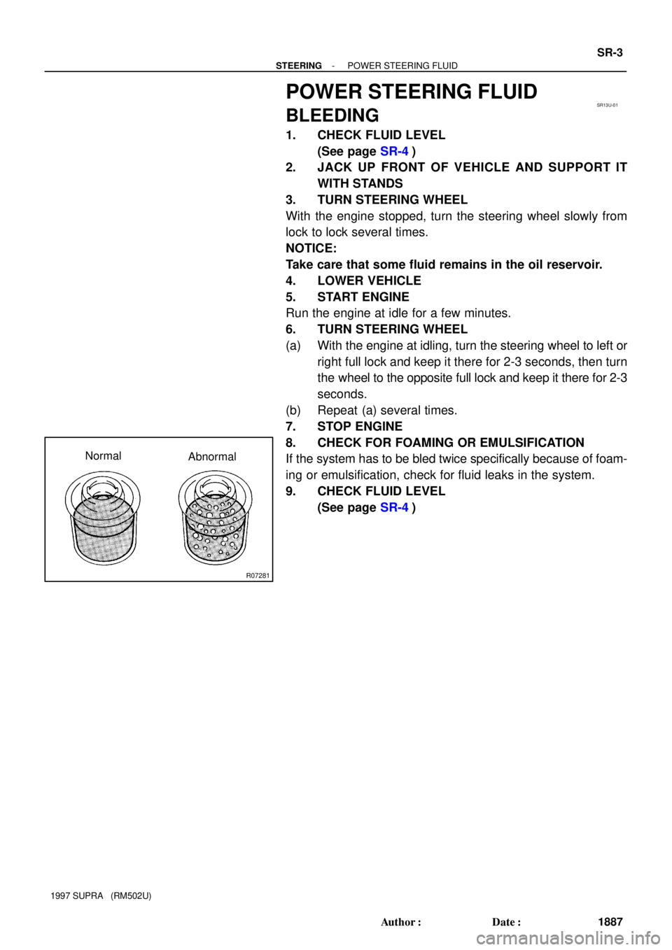
Normal
Abnormal
- STEERINGPOWER STEERING FLUID
SR-3
1887 Author�: Date�:
1997 SUPRA (RM502U)
POWER STEERING FLUID
BLEEDING
1. CHECK FLUID LEVEL
(See page SR-4)
2. JACK UP FRONT OF VEHICLE AND SUPPORT IT
WITH STANDS
3. TURN STEERING WHEEL
With the engine stopped, turn the steering wheel slowly from
lock to lock several times.
NOTICE:
Take care that some fluid remains in the oil reservoir.
4. LOWER VEHICLE
5. START ENGINE
Run the engine at idle for a few minutes.
6. TURN STEERING WHEEL
(a) With the engine at idling, turn the steering wheel to left or
right full lock and keep it there for 2-3 seconds, then turn
the wheel to the opposite full lock and keep it there for 2-3
seconds.
(b) Repeat (a) several times.
7. STOP ENGINE
8. CHECK FOR FOAMING OR EMULSIFICATION
If the system has to be bled twice specifically because of foam-
ing or emulsification, check for fluid leaks in the system.
9. CHECK FLUID LEVEL
(See page SR-4)
Page 1573 of 1807

or less
Engine Idling Engine Stopped SR-4
- STEERINGPOWER STEERING FLUID
1888 Author�: Date�:
1997 SUPRA (RM502U)
INSPECTION
1. C")
SR13V-01
R00441
R07281
Normal Abnormal
R10552
5 mm (0.20 in.)
or less
Engine Idling Engine Stopped SR-4
- STEERINGPOWER STEERING FLUID
1888 Author�: Date�:
1997 SUPRA (RM502U)
INSPECTION
1. CHECK FLUID LEVEL
(a) Keep the vehicle level.
With the engine stopped, check the fluid level in the oil
reservoir.
If necessary, add fluid.
Fluid: ATF DEXRON® II or III
HINT:
Check that the fluid level is within the HOT LEVEL range on the
dipstick of the reservoir cap. If the fluid is cold, check that it is
within the COLD LEVEL range.
(b) Start the engine and run it at idle.
(c) Turn the steering wheel from lock to lock several times to
boost fluid temperature.
Fluid temperature: 80°C (176°F)
(d) Check for foaming or emulsification.
If there is foaming or emulsification, bleed power steering sys-
tem.
(See page SR-3)
(e) With the engine idling, measure the fluid level in the oil
reservoir.
(f) Stop the engine.
(g) Wait a few minutes and remeasure the fluid level in the
reservoir.
Maximum fluid level rise: 5mm (0.20 in.)
If a problem is found, bleed power steering system.
(See page SR-3)
(h) Check the fluid level.