Page 746 of 1807
F02629F02630F02631
LOCK
A9
(+)
(-)
W02799
ABS Solenoid
Relay
ABS
Actuator
ECUA9
A6A6
A6A6
A19
16
5
4
5
4
5
- DIAGNOSTICSANTI-LOCK BRAKE SYSTEM
DI-455
683 Author�: Date�:
1997 SUPRA (RM502U)
INSPECTION PROCEDURE (2JZ-GE Engine)
1 Check voltage between terminals A9 - 2 and A9 - 6 of ABS control (solenoid)
relay connector.
PREPARATION:
Disconnect the ABS control (solenoid) relay connector.
CHECK:
Measure voltage between terminals A9 - 2 and A9 - 6 of ABS
control (solenoid) relay harness side connector.
OK:
Voltage: 10 - 14 V
NG Check and repair harness or connector.
OK
2 Check continuity between terminal A9 - 5 of ABS control (solenoid) relay con-
nector and terminal A19 - 16 of ABS ECU.
CHECK:
Check continuity between terminal A9 - 5 of ABS control (sole-
noid) relay connector and terminal A19 - 16 of ABS ECU.
OK:
Continuity
HINT:
There is a resistance of 26 ~ 40 W between terminals A6 - 4 and
A6 - 5 of ABS actuator.
NG Repair or replace harness or ABS actuator.
OK
Page 748 of 1807
F02629F02636F02637
LOCK
R/B No.5
(-)
(+)
- DIAGNOSTICSANTI-LOCK BRAKE SYSTEM
DI-457
685 Author�: Date�:
1997 SUPRA (RM502U)
INSPECTION PROCEDURE (2JZ-GTE Engine)
1 Check voltage between terminals 1 and 2 of R/B No.5 (for ABS solenoid relay).
PREPARATION:
Remove ABS solenoid relay from R/B No.5.
CHECK:
Measure voltage between terminals 1 and 2 of R/B No.5 (for
ABS solenoid relay).
OK:
Voltage: 10 - 14 V
NG Check and repair harness or connector.
OK
Page 753 of 1807
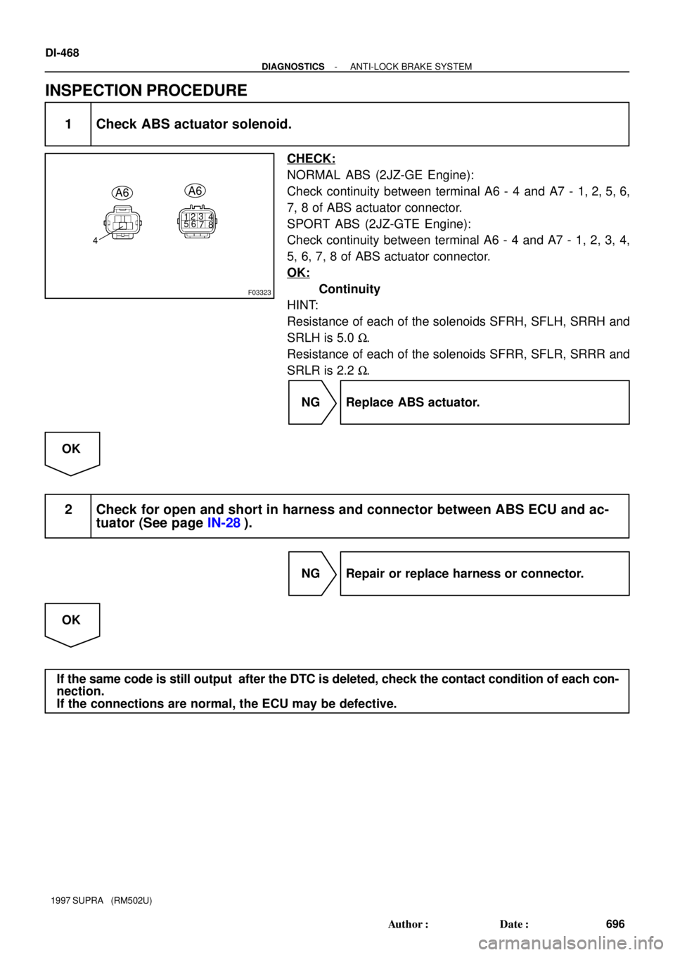
F03323
123
4
56
7
8
4
A6A6
DI-468
- DIAGNOSTICSANTI-LOCK BRAKE SYSTEM
696 Author�: Date�:
1997 SUPRA (RM502U)
INSPECTION PROCEDURE
1 Check ABS actuator solenoid.
CHECK:
NORMAL ABS (2JZ-GE Engine):
Check continuity between terminal A6 - 4 and A7 - 1, 2, 5, 6,
7, 8 of ABS actuator connector.
SPORT ABS (2JZ-GTE Engine):
Check continuity between terminal A6 - 4 and A7 - 1, 2, 3, 4,
5, 6, 7, 8 of ABS actuator connector.
OK:
Continuity
HINT:
Resistance of each of the solenoids SFRH, SFLH, SRRH and
SRLH is 5.0 W.
Resistance of each of the solenoids SFRR, SFLR, SRRR and
SRLR is 2.2 W.
NG Replace ABS actuator.
OK
2 Check for open and short in harness and connector between ABS ECU and ac-
tuator (See page IN-28).
NG Repair or replace harness or connector.
OK
If the same code is still output after the DTC is deleted, check the contact condition of each con-
nection.
If the connections are normal, the ECU may be defective.
Page 756 of 1807
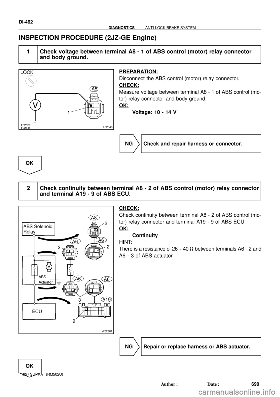
F02629F02645F02646
LOCK
A8
W02801
ABS Solenoid
Relay
ABS
Actuator
ECUA8
A6A6
A6A6
A193
9
22
2
DI-462
- DIAGNOSTICSANTI-LOCK BRAKE SYSTEM
690 Author�: Date�:
1997 SUPRA (RM502U)
INSPECTION PROCEDURE (2JZ-GE Engine)
1 Check voltage between terminal A8 - 1 of ABS control (motor) relay connector
and body ground.
PREPARATION:
Disconnect the ABS control (motor) relay connector.
CHECK:
Measure voltage between terminal A8 - 1 of ABS control (mo-
tor) relay connector and body ground.
OK:
Voltage: 10 - 14 V
NG Check and repair harness or connector.
OK
2 Check continuity between terminal A8 - 2 of ABS control (motor) relay connector
and terminal A19 - 9 of ABS ECU.
CHECK:
Check continuity between terminal A8 - 2 of ABS control (mo-
tor) relay connector and terminal A19 - 9 of ABS ECU.
OK:
Continuity
HINT:
There is a resistance of 26 ~ 40 W between terminals A6 - 2 and
A6 - 3 of ABS actuator.
NG Repair or replace harness or ABS actuator.
OK
Page 758 of 1807
F02629F02649F02650
LOCK
R/B No.5
(+) (-)
F03315
ABS Solenoid
Relay
ABS
Actuator
ECUA6
A6
A6A6
A21
2
22
3
10
DI-464
- DIAGNOSTICSANTI-LOCK BRAKE SYSTEM
692 Author�: Date�:
1997 SUPRA (RM502U)
INSPECTION PROCEDURE (2JZ-GTE Engine)
1 Check voltage between terminal 1 of R/B No.5 (for ABS motor relay) and body
ground.
PREPARATION:
Remove ABS motor relay from R/B No.5.
CHECK:
Measure voltage between terminal 1 of R/B No.5 (for ABS mo-
tor relay) and body ground.
OK:
Voltage: 10 - 14 V
NG Check and repair harness or connector.
OK
2 Check continuity between terminal 2 of R/B No.5 (for ABS motor relay) and termi-
nal A21 - 10 of ABS ECU.
CHECK:
Check continuity between terminal 2 of R/B No.5 (for ABS mo-
tor relay) and terminal A21 - 10 of ABS ECU.
OK:
Continuity
HINT:
There is a resistance of 26 ~ 40 W between terminals A6 - 2 and
A6 - 3 of ABS actuator.
NG Repair or replace harness or ABS actuator.
OK
Page 768 of 1807
F02629F03334F03335F03336
NORMAL ABS (2JZ-GE Engine):
SPORT ABS (2JZ-GTE Engine):
LOCK
GND
(+)
(-)
(+)
(-)GND
GND
GND
- DIAGNOSTICSANTI-LOCK BRAKE SYSTEM
DI-477
705 Author�: Date�:
1997 SUPRA (RM502U)
3 Check continuity between terminal GND of ABS ECU connector and body
ground.
CHECK:
Measure resistance between terminals GND of ABS ECU con-
nector and body ground.
OK:
Resistance: 1 W or less
NG Repair or replace harness or connector.
OK
Page 770 of 1807

DTC 43, 45 Malfunction is Deceleration Sensor
(SPORT ABS (2JZ-GTE Engine) only)
CIRCUIT DESCRIPTION
DTC No.DTC Dete")
- DIAGNOSTICSANTI-LOCK BRAKE SYSTEM
DI-479
707 Author�: Date�:
1997 SUPRA (RM502U)
DTC 43, 45 Malfunction is Deceleration Sensor
(SPORT ABS (2JZ-GTE Engine) only)
CIRCUIT DESCRIPTION
DTC No.DTC Detecting ConditionTrouble Area
43
Either of the following (1) or (2) is detected:
(1) Input from the deceleration sensor does not change at one
cycle (0 km/h " more than 30km/h " 0 km/h) for 16 times
continuously.
(2) When the brake pedal is not depressed at vehicle speed of
5 km/h or more, forward and backward G (more than 0.4 G) is
detected for 30 seconds or more.
�Deceleration sensor
�Wire harness for deceleration sensor system
45
At vehicle speed of 30 km/h or more, the deceleration sensor
output and vehicle acceleration from wheel speed remain ab-
normally different for 60 seconds or more.�Deceleration sensor
�Wire harness for deceleration sensor system
INSPECTION PROCEDURE
1 Check deceleration sensor (See page DI-442).
NG Replace deceleration sensor.
OK
2 Check for open or short in harness and connector between sensor and ABS ECU
(See page IN-28).
NG Repair or replace harness and connector.
OK
Check and replace ABS ECU.
DI4VG-01
Page 773 of 1807
F03341
R/B No.2J/B No.1Stop Light
SwitchABS ECU
125
Light
Failure
Sensor
Stop LightJ/B
No.11
10IH
IC
A18 A22 *1*2
G-WG-W
G-W1
2 W STOP
210
1B 1I W-LPOWER
22 W
2
2A
ALTR/B No.2
B
Battery
NORMAL ABS (2JZ-GE Engine)
SPORT ABS (2JS-GTE Engine)
*1:
*2:
1
DI-482
- DIAGNOSTICSANTI-LOCK BRAKE SYSTEM
710 Author�: Date�:
1997 SUPRA (RM502U)
DTC 49 Stop Light Switch Circuit
CIRCUIT DESCRIPTION
This stop light switch senses whether the brake pedal is depressed or released, and sends a signal to the
ECU.
DTC No.DTC Detecting ConditionTrouble Area
491.2 - 1.7 V of STP voltage is continued for 0.3 sec. or more.�Open in stop light circuit
WIRING DIAGRAM
INSPECTION PROCEDURE
1 Check operation of stop light.
CHECK:
Check that stop light lights up when brake pedal is depressed and turns off when brake pedal is released.
NG Replace stop light bulb.
OK
DI4VI-01