Page 725 of 1807
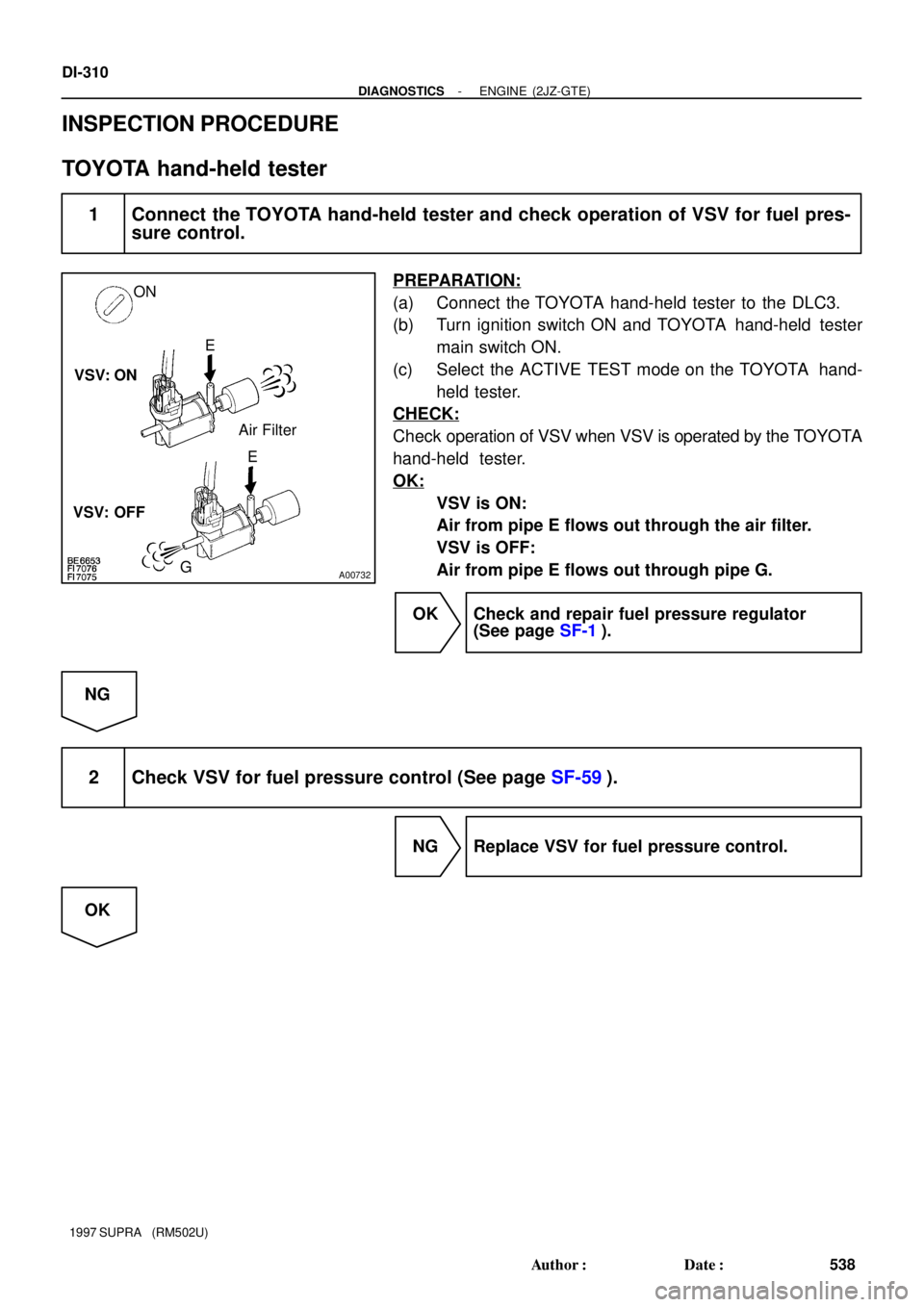
A00732
ON
E
Air Filter
E
G VSV: ON
VSV: OFF
DI-310
- DIAGNOSTICSENGINE (2JZ-GTE)
538 Author�: Date�:
1997 SUPRA (RM502U)
INSPECTION PROCEDURE
TOYOTA hand-held tester
1 Connect the TOYOTA hand-held tester and check operation of VSV for fuel pres-
sure control.
PREPARATION:
(a) Connect the TOYOTA hand-held tester to the DLC3.
(b) Turn ignition switch ON and TOYOTA hand-held tester
main switch ON.
(c) Select the ACTIVE TEST mode on the TOYOTA hand-
held tester.
CHECK:
Check operation of VSV when VSV is operated by the TOYOTA
hand-held tester.
OK:
VSV is ON:
Air from pipe E flows out through the air filter.
VSV is OFF:
Air from pipe E flows out through pipe G.
OK Check and repair fuel pressure regulator
(See page SF-1).
NG
2 Check VSV for fuel pressure control (See page SF-59).
NG Replace VSV for fuel pressure control.
OK
Page 726 of 1807
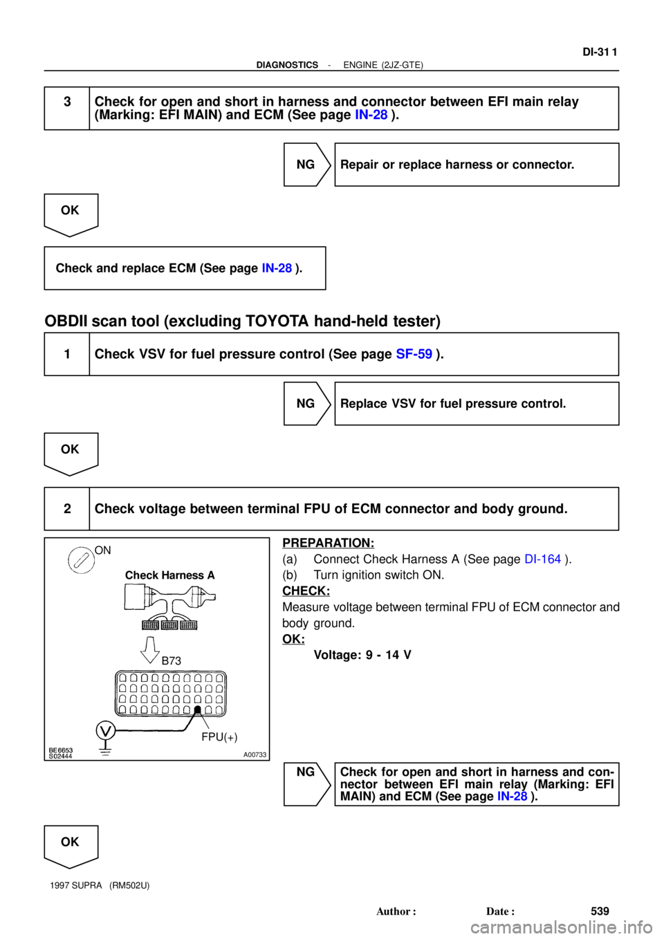
A00733
ON
Check Harness A
B73
FPU(+)
- DIAGNOSTICSENGINE (2JZ-GTE)
DI-31 1
539 Author�: Date�:
1997 SUPRA (RM502U)
3 Check for open and short in harness and connector between EFI main relay
(Marking: EFI MAIN) and ECM (See page IN-28).
NG Repair or replace harness or connector.
OK
Check and replace ECM (See page IN-28).
OBDII scan tool (excluding TOYOTA hand-held tester)
1 Check VSV for fuel pressure control (See page SF-59).
NG Replace VSV for fuel pressure control.
OK
2 Check voltage between terminal FPU of ECM connector and body ground.
PREPARATION:
(a) Connect Check Harness A (See page DI-164).
(b) Turn ignition switch ON.
CHECK:
Measure voltage between terminal FPU of ECM connector and
body ground.
OK:
Voltage: 9 - 14 V
NG Check for open and short in harness and con-
nector between EFI main relay (Marking: EFI
MAIN) and ECM (See page IN-28).
OK
Page 727 of 1807
DI-312
- DIAGNOSTICSENGINE (2JZ-GTE)
540 Author�: Date�:
1997 SUPRA (RM502U)
3 Check fuel pressure regulator (See page SF-1).
NG Repair or replace.
OK
Check and replace ECM (See page IN-28).
Page 728 of 1807

DI-313
541 Author�: Date�:
1997 SUPRA (RM502U)
A/C Cut Control Circuit
CIRCUIT DESCRIPTION
This circuit cuts air")
P19604
A/C Amplifier
5 V
6
A14L-R31
II1L-R34
AAC1ECM
E1
- DIAGNOSTICSENGINE (2JZ-GTE)
DI-313
541 Author�: Date�:
1997 SUPRA (RM502U)
A/C Cut Control Circuit
CIRCUIT DESCRIPTION
This circuit cuts air conditioning operation during vehicle acceleration in order to increase acceleration per-
formance. During acceleration with the vehicle speed at 25 km/h (16 mph) or less, engine speed at 1,200
rpm or less and throttle valve opening angle at 60° or more, the A/C magnet switch is turned OFF for several
seconds.
WIRING DIAGRAM
INSPECTION PROCEDURE
TOYOTA hand-held tester
1 Connect the TOYOTA hand-held tester and check operation of air conditioning
cut control.
PREPARATION:
(a) Connect the TOYOTA hand-held tester to the DLC3.
(b) Turn ignition switch ON and push TOYOTA hand-held tester main switch ON.
(c) Start the engine and air conditioning switch ON.
HINT:
A/C magnetic clutch is turned ON.
(d) Select the ACTIVE TEST mode on the TOYOTA hand-held tester.
CHECK:
Check operation of A/C magnetic clutch cut when air conditioning cut control is operated by the TOYOTA
hand-held tester.
OK:
A/C magnetic clutch is turned OFF.
DI4TW-01
Page 729 of 1807
S03240
Check Harness A
AC1 (+)
DI-314
- DIAGNOSTICSENGINE (2JZ-GTE)
542 Author�: Date�:
1997 SUPRA (RM502U)
OK Proceed to next circuit inspection shown on
matrix chart (See page DI-169).
NG
2 Check for open and short in harness and connector between ECM and A/C am-
plifier (See page IN-28).
NG Repair or replace harness or connector.
OK
3 Check voltage between terminal AC1 of ECM connector and body ground.
PREPARATION:
(a) Connect Check Harness A (See page DI-164).
(b) Start the engine.
CHECK:
Measure voltage between terminal AC1 of ECM connector and
body ground when A/C switch is turned to ON and OFF.
OK:
A/C Switch ConditionVoltage
ON0 - 1.5 V
OFF7.5 - 14 V
NG Check and replace A/C amplifier.
OK
Check and replace ECM (See page IN-28).
Page 730 of 1807
- DIAGNOSTICSENGINE (2JZ-GTE)
DI-315
543 Author�: Date�:
1997 SUPRA (RM502U)
OBDII scan tool (excluding TOYOTA hand-held tester)
1 Check voltage between terminal AC1 of ECM and body ground (See page
DI-313, step 3).
OK Check and replace ECM (See page IN-28).
NG
2 Check for open and short in harness and connector between ECM and A/C am-
plifier (See page IN-28).
NG Repair or replace harness or connector.
OK
Check and replace A/C amplifier.
Page 735 of 1807

7276
ON
OFF
0.5 sec.
0.5 sec.1.5 sec.
0.5 sec.0.5 sec.2.5 sec.
4 sec.
Repeat DI-444
- DI")
F00007
E1
Tc
Ts
lei-23-1-A
DLC1
BR3904
0.13 sec.
0.13 sec.
ON
OFF
BR3893
Malfunction Code (Example Code 72, 76)
7276
ON
OFF
0.5 sec.
0.5 sec.1.5 sec.
0.5 sec.0.5 sec.2.5 sec.
4 sec.
Repeat DI-444
- DIAGNOSTICSANTI-LOCK BRAKE SYSTEM
672 Author�: Date�:
1997 SUPRA (RM502U)
2. SPEED SENSOR SIGNAL AND DECELERATION SEN-
SOR
(a) Check the speed sensor signal and deceleration sensor.
(1) Turn the ignition switch OFF
(2) Using SST, connect terminal Ts and E1 of DLC1.
SST 09843-18020
(3) Start the engine.
(4) Check that the ABS warning light blinks.
HINT:
�If the ABS warning light does not blink, inspect the ABS
warning light circuit (See page DI-488).
�If the ABS warning light is always on, inspect and repair,
deceleration sensor.
(5) Drive the vehicle faster than 45 km/h (28 mph) for
several seconds.
(6) Stop the vehicle.
(7) Using SST, connect terminals Tc an E1 of DLC1.
SST 09843-18020
(8) Read the number of blinks of the ABS warning light.
HINT:
�See the list of DTC shown on the next page.
�If every sensor is normal, a normal code is output (A cycle
of 0.25 sec. ON and 0.25 sec. OFF is repeated).
�If 2 or more malfunctions are indicated at the same time,
the lowest numbered code will be displayed 1st.
(9) After doing the check, disconnect terminals Ts and
E1, Tc and E1 of DLC1, and turn ignition switch OFF.
Page 736 of 1807

(b) Using TOYOTA hand-held tester, check the DTC.
(1) Do step (1) - (6) on")
FI6997
TOYOTA
Hand-held
tester
DLC2
- DIAGNOSTICSANTI-LOCK BRAKE SYSTEM
DI-445
673 Author�: Date�:
1997 SUPRA (RM502U)
(b) Using TOYOTA hand-held tester, check the DTC.
(1) Do step (1) - (6) on the previous page.
(2) Hook up the TOYOTA hand- held tester to the
DLC2.
(3) Read the DTC by following the prompts on the tes-
ter screen.
Please refer to the TOYOTA hand-held tester oper-
ator 's manual for farther details.
DTC of speed sensor check function:
Code No.DiagnosisTrouble Area
71Low output voltage of right front speed sensor
�Right front speed sensor
�Sensor installation
�Sensor Rotor
72Low output voltage of left front speed sensor
�Left front speed sensor
�Sensor installation
�Sensor Rotor
73Low output voltage of right rear speed sensor
�Right rear speed sensor
�Sensor installation
�Sensor Rotor
74Low output voltage of left rear speed sensor
�Left rear speed sensor
�Sensor installation
�Sensor Rotor
75Abnormal change in output voltage of right front speed sensor�Right front speed sensor rotor
76Abnormal change in output voltage of left front speed sensor�Left front speed sensor rotor
77Abnormal change in output voltage of right rear speed sensor�Right rear speed sensor rotor
78Abnormal change in output voltage of left rear speed sensor�Left rear speed sensor rotor
79*Deceleration sensor is faulty�Deceleration sensor
�Sensor installation
*: SPORT ABS (2JZ-GTE Engine) only