Page 666 of 1807
- DIAGNOSTICSENGINE (2JZ-GTE)
DI-251
479 Author�: Date�:
1997 SUPRA (RM502U)
7 Check for open and short in harness and connector between terminals DI of
ECM and 6 of fuel pump ECU (See page IN-28).
NG Repair or replace harness or connector.
OK
Check and replace ECM.
Page 668 of 1807
A00720
ONCheck Harness A
ECM
B58
IGF(+)
- DIAGNOSTICSENGINE (2JZ-GTE)
DI-253
481 Author�: Date�:
1997 SUPRA (RM502U)
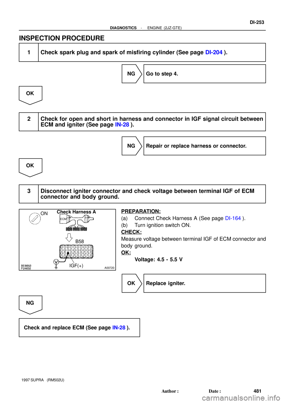
INSPECTION PROCEDURE
1 Check spark plug and spark of misfiring cylinder (See page DI-204).
NG Go to step 4.
OK
2 Check for open and short in harness and connector in IGF signal circuit between
ECM and igniter (See page IN-28).
NG Repair or replace harness or connector.
OK
3 Disconnect igniter connector and check voltage between terminal IGF of ECM
connector and body ground.
PREPARATION:
(a) Connect Check Harness A (See page DI-164).
(b) Turn ignition switch ON.
CHECK:
Measure voltage between terminal IGF of ECM connector and
body ground.
OK:
Voltage: 4.5 - 5.5 V
OK Replace igniter.
NG
Check and replace ECM (See page IN-28).
Page 669 of 1807
BE6653S02439A03139
START
Check Harness A
ECM
57, 56, 55, 54
53, 52 IGT3
(+)
IGT2
(+)
IGT1
(+)
IGT4
(+)IGT5
(+)IGT6
(+)
FI6952
IGT 1 - 6, IGF signal waveform
2 V/
Division
IGT 1 - 6
0
IGF
0
20 msec./Division (Idling)
DI-254
- DIAGNOSTICSENGINE (2JZ-GTE)
482 Author�: Date�:
1997 SUPRA (RM502U)
4 Check for open and short in harness and connector in IGT 1 ~ 6 signal circuit
between ECM and igniter (See page IN-28).
NG Repair or replace harness or connector.
OK
5 Check voltage between terminal IGT 1 - 6 of ECM connector and body ground.
PREPARATION:
Connect Check Harness A (See page DI-164).
CHECK:
Measure voltage between terminal IGT 1 ~ 6 of ECM connector
and body ground when engine is cranked.
OK:
Voltage: More than 0.1 V and less than 4.5 V
Reference INSPECTION USING OSCILLOSCOPE
During cranking or idling, check waveforms between terminal
IGT 1 - 6, IGF and E1 of ECM.
HINT:
The correct rectangular waveforms are as shown.
NG Check and replace ECM (See page IN-28).
OK
Page 670 of 1807
BE6653S02439A03139
START
Check Harness A
ECM
57, 56, 55, 54
53, 52 IGT3
(+)
IGT2
(+)
IGT1
(+)
IGT4
(+)IGT5
(+)IGT6
(+)
BE6653S02440A06728
ON " START
2(+)
- DIAGNOSTICSENGINE (2JZ-GTE)
DI-255
483 Author�: Date�:
1997 SUPRA (RM502U)
6 Disconnect igniter connector and check voltage between terminal IGT 1 ~ 6 of
ECM connector and body ground.
PREPARATION:
(a) Disconnect igniter connector.
(b) Connect Check Harness A (See page DI-164).
CHECK:
Measure voltage between terminal IGT 1 - 6 of ECM connector
and body ground when engine is cranked.
OK:
Voltage: More than 0.1 V and less than 4.5 V
NG Check and replace ECM (See page IN-28).
OK
7 Check voltage between terminal 2 of igniter connector and body ground.
PREPARATION:
Disconnect igniter connector.
CHECK:
Measure voltage between terminal 2 of igniter connector and
body ground, when ignition switch is turned to ºONº and
ºSTARTº position.
OK:
Voltage: 9 - 14 V
NG Check and repair igniter power source circuit.
OK
Page 671 of 1807
DI-256
- DIAGNOSTICSENGINE (2JZ-GTE)
484 Author�: Date�:
1997 SUPRA (RM502U)
8 Check for open and short in harness and connector between ignition switch and
ignition coil, ignition coil and igniter (See page IN-28).
NG Repair or replace harness or connector.
OK
9 Check ignition coil (See page IG-1).
NG Replace ignition coil.
OK
Replace igniter.
Page 674 of 1807
BE6653P23933A07640A06729
ON
Check Harness A
ECM
B65, 63, 42
VTA2 (+)
IDL2 (+) E2 (-)
Sub Throttle Valve
- DIAGNOSTICSENGINE (2JZ-GTE)
DI-259
487 Author�: Date�:
1997 SUPRA (RM502U)
INSPECTION PROCEDURE
1 Check voltage between terminals VTA2, IDL2 and E2 of ECM.
PREPARATION:
(a) Connect Check Harness A (See page DI-164).
(b) Turn ignition switch ON.
(c) Remove intake air connector pipe and disconnect sub
throttle valve actuator connector.
CHECK:
Measure voltage between terminals VTA2, IDL2 and E2 of ECM
when the sub throttle valve is opened gradually from the closed
condition.
OK:
Throttle ValveTerminal VTA2Terminal IDL2
Fully Closed0.3 - 0.8 V0 - 3.0 V
Fully Open3.2 - 4.9 V9 - 14 V
HINT:
The voltage should increase steadily in proportion to the throttle
valve opening angle.
OK Check for intermittent problems
(See page DI-147).
NG
Page 675 of 1807
S03246S02441A03142
Sub Throttle Position Sensor
1
2
3
DI-260
- DIAGNOSTICSENGINE (2JZ-GTE)
488 Author�: Date�:
1997 SUPRA (RM502U)
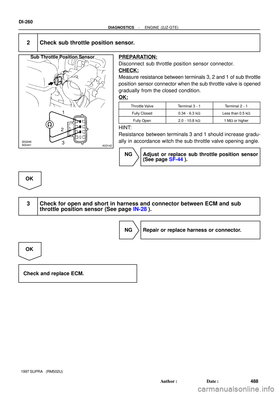
2 Check sub throttle position sensor.
PREPARATION:
Disconnect sub throttle position sensor connector.
CHECK:
Measure resistance between terminals 3, 2 and 1 of sub throttle
position sensor connector when the sub throttle valve is opened
gradually from the closed condition.
OK:
Throttle ValveTerminal 3 - 1Terminal 2 - 1
Fully Closed0.34 - 6.3 kWLess than 0.5 kW
Fully Open2.0 - 10.8 kW1 MW or higher
HINT:
Resistance between terminals 3 and 1 should increase gradu-
ally in accordance witch the sub throttle valve opening angle.
NG Adjust or replace sub throttle position sensor
(See page SF-44).
OK
3 Check for open and short in harness and connector between ECM and sub
throttle position sensor (See page IN-28).
NG Repair or replace harness or connector.
OK
Check and replace ECM.
Page 678 of 1807
BE6653S02442A06730
SST
E1 (-)
B69, 41
VCC (+)
ECM
ON
- DIAGNOSTICSENGINE (2JZ-GTE)
DI-263
491 Author�: Date�:
1997 SUPRA (RM502U)
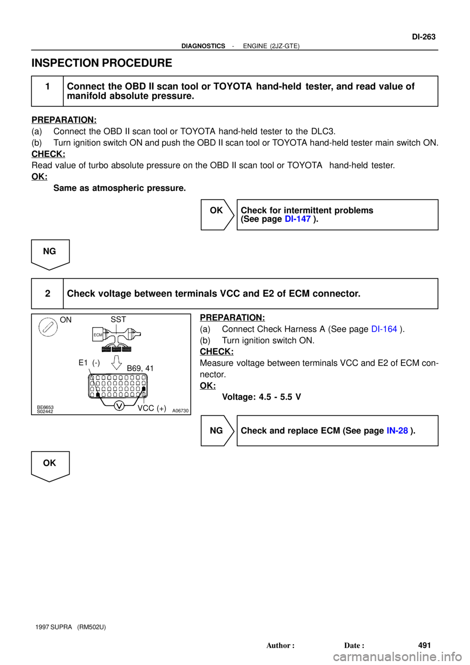
INSPECTION PROCEDURE
1 Connect the OBD II scan tool or TOYOTA hand-held tester, and read value of
manifold absolute pressure.
PREPARATION:
(a) Connect the OBD II scan tool or TOYOTA hand-held tester to the DLC3.
(b) Turn ignition switch ON and push the OBD II scan tool or TOYOTA hand-held tester main switch ON.
CHECK:
Read value of turbo absolute pressure on the OBD II scan tool or TOYOTA hand-held tester.
OK:
Same as atmospheric pressure.
OK Check for intermittent problems
(See page DI-147).
NG
2 Check voltage between terminals VCC and E2 of ECM connector.
PREPARATION:
(a) Connect Check Harness A (See page DI-164).
(b) Turn ignition switch ON.
CHECK:
Measure voltage between terminals VCC and E2 of ECM con-
nector.
OK:
Voltage: 4.5 - 5.5 V
NG Check and replace ECM (See page IN-28).
OK


IGT2
(+)
IGT1
(+)
IGT4
(+)IGT5
(+)IGT6
(+)
FI6952
IGT 1 - 6, IGF signal waveform
2 V/
Division
IGT 1 - 6
0
IGF
0
20 msec./Di")

IGT2
(+)
IGT1
(+)
IGT4
(+)IGT5
(+)IGT6
(+)
BE6653S02440A06728
ON \" START
2(+)
- DIAGNOSTICSENGINE (2JZ-GTE)
DI-255
483 Autho")