Page 645 of 1807
(2)(3) (4)
FI6514
OX Signal Waveform (Oscilloscope)
200 msec./Division 1.0 V
0 V DI-232
- DIAGNOSTICSENGINE (")
FI7132
Engine Speed
2,500 - 3,000 rpm
Idling
IG SW OFF
Warmed up 3 min. or so CheckTime (1)(2)(3) (4)
FI6514
OX Signal Waveform (Oscilloscope)
200 msec./Division 1.0 V
0 V DI-232
- DIAGNOSTICSENGINE (2JZ-GTE)
460 Author�: Date�:
1997 SUPRA (RM502U)
CONFIRMATION ENGINE RACING PATTERN
(1) Connect the TOYOTA hand-held tester to the DLC3, or connect the probe of the oscilloscope between
terminals OX1, OX2, and E1 of ECM.
(2) Start engine and warm it up with all accessories switched OFF until water temperature is stable.
(3) Race the engine at 2,500 ~ 3,000 rpm for about 3 min.
(4) After confirming that the waveforms of the heated oxygen sensors, bank 1 sensor 1 (OX1), oscillate
around 0.5 V during feedback to the ECM, check the waveform of the heated oxygen senor, bank 1 sensor
2 (OX2).
HINT:
If there is a malfunction in the system, the waveform of the
heated oxygen senor, bank1 sensor 2 (OX2), is almost the
same as that of the heated oxygen sensors, bank 1 senor 1
(OX1), on the left.
There are some cases where, even though a malfunction ex-
ists, the MIL may either light up or not light up.
Page 646 of 1807
- DIAGNOSTICSENGINE (2JZ-GTE)
DI-233
461 Author�: Date�:
1997 SUPRA (RM502U)
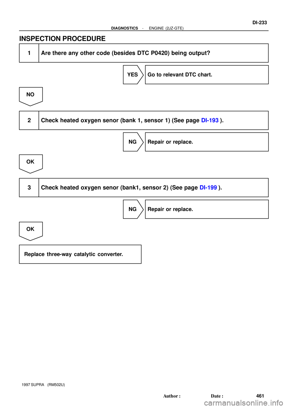
INSPECTION PROCEDURE
1 Are there any other code (besides DTC P0420) being output?
YES Go to relevant DTC chart.
NO
2 Check heated oxygen senor (bank 1, sensor 1) (See page DI-193).
NG Repair or replace.
OK
3 Check heated oxygen senor (bank1, sensor 2) (See page DI-199).
NG Repair or replace.
OK
Replace three-way catalytic converter.
Page 648 of 1807
A00711
ON
Air
Air
FEF
E
VSV: ON VSV: OFF
- DIAGNOSTICSENGINE (2JZ-GTE)
DI-235
463 Author�: Date�:
1997 SUPRA (RM502U)
INSPECTION PROCEDURE
TOYOTA hand-held tester
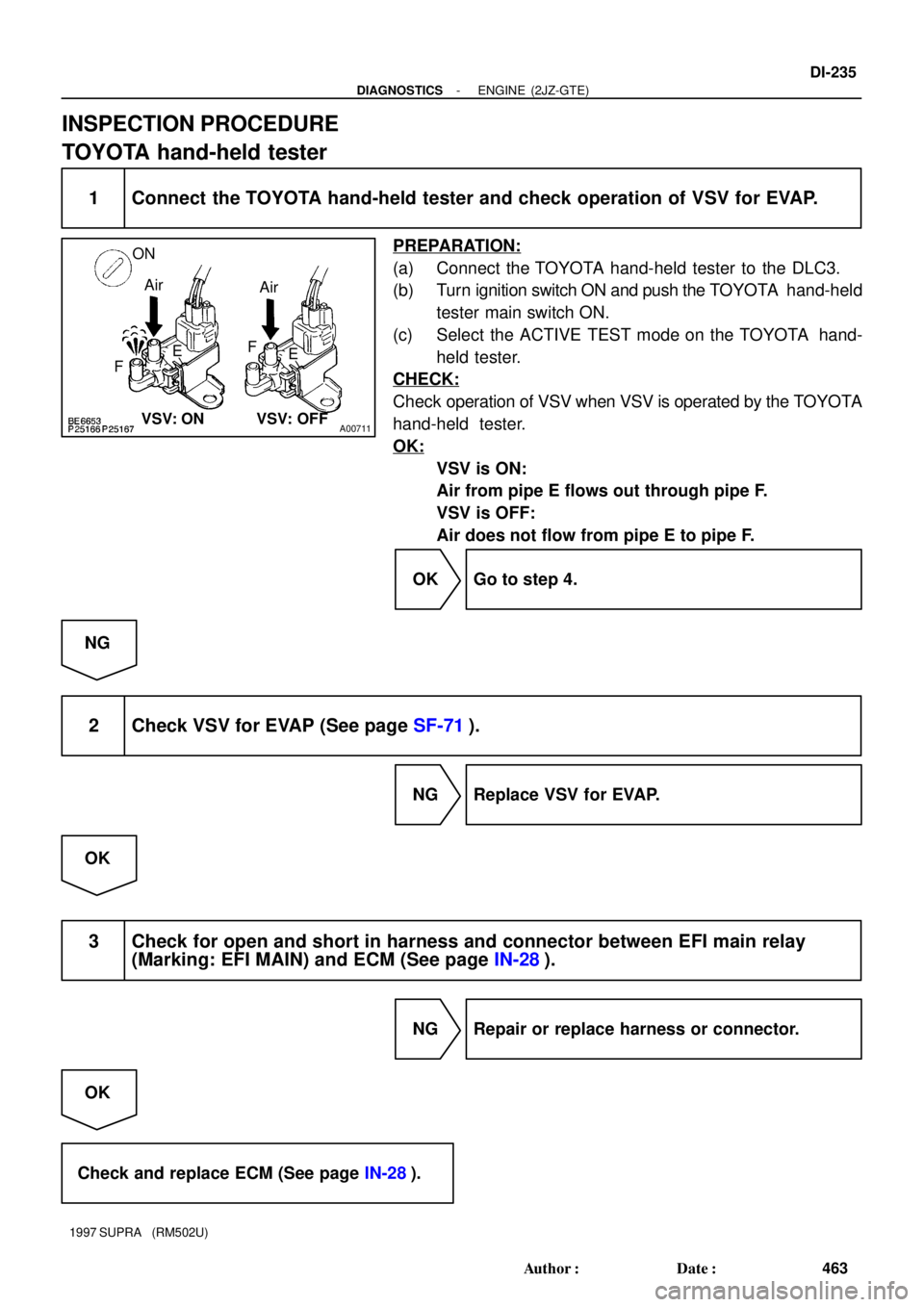
1 Connect the TOYOTA hand-held tester and check operation of VSV for EVAP.
PREPARATION:
(a) Connect the TOYOTA hand-held tester to the DLC3.
(b) Turn ignition switch ON and push the TOYOTA hand-held
tester main switch ON.
(c) Select the ACTIVE TEST mode on the TOYOTA hand-
held tester.
CHECK:
Check operation of VSV when VSV is operated by the TOYOTA
hand-held tester.
OK:
VSV is ON:
Air from pipe E flows out through pipe F.
VSV is OFF:
Air does not flow from pipe E to pipe F.
OK Go to step 4.
NG
2 Check VSV for EVAP (See page SF-71).
NG Replace VSV for EVAP.
OK
3 Check for open and short in harness and connector between EFI main relay
(Marking: EFI MAIN) and ECM (See page IN-28).
NG Repair or replace harness or connector.
OK
Check and replace ECM (See page IN-28).
Page 649 of 1807
A00712
ONCheck Harness AECM
B74
EVAP(+)
DI-236
- DIAGNOSTICSENGINE (2JZ-GTE)
464 Author�: Date�:
1997 SUPRA (RM502U)
4 Check connection of vacuum hose (See page EC-5).
NG Repair or replace.
OK
Check and repair charcoal canister (See
page EC-5).
OBDII scan tool (excluding TOYOTA hand-held tester)
1 Check VSV for EVAP (See page SF-71).
NG Replace VSV for EVAP.
OK
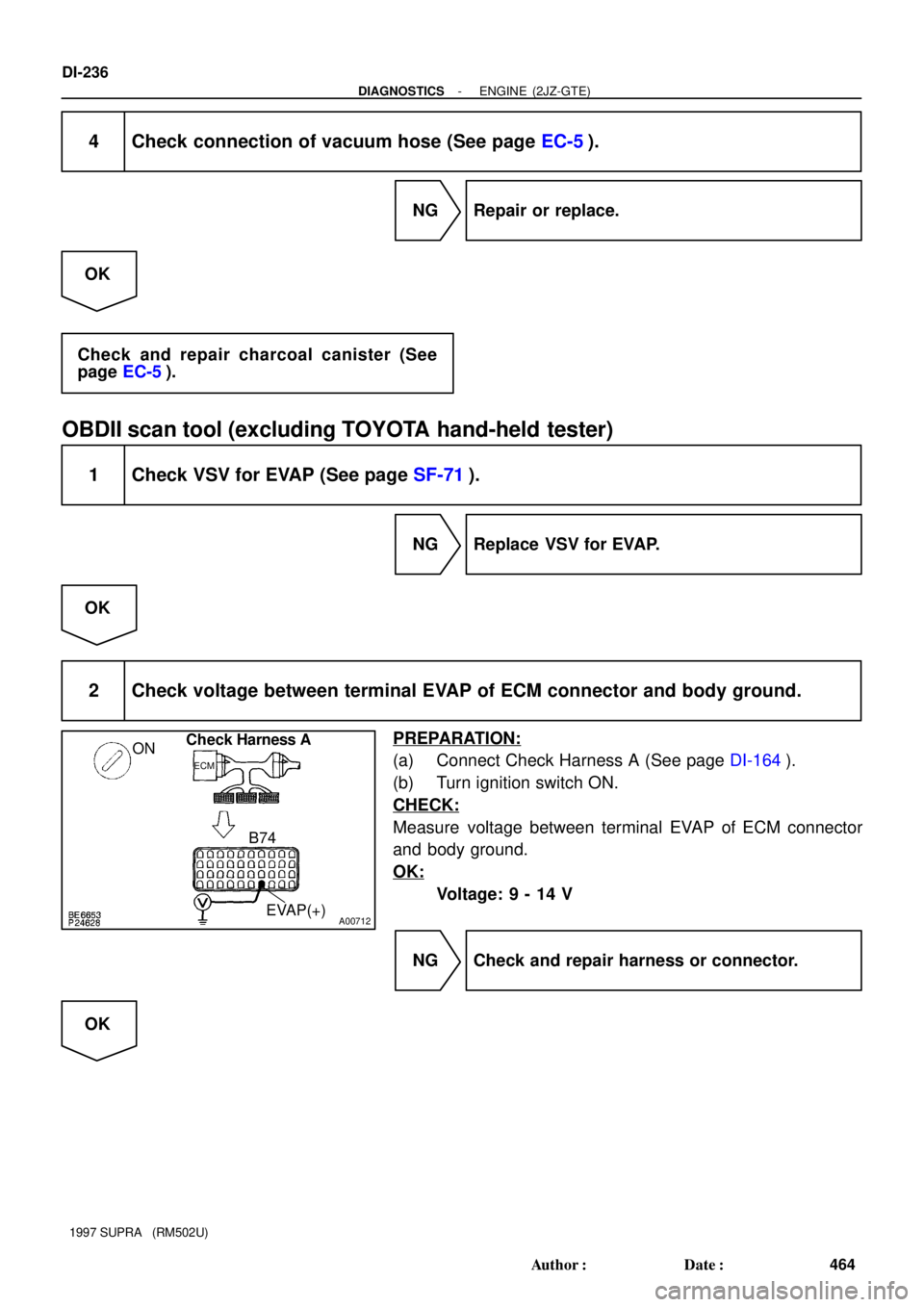
2 Check voltage between terminal EVAP of ECM connector and body ground.
PREPARATION:
(a) Connect Check Harness A (See page DI-164).
(b) Turn ignition switch ON.
CHECK:
Measure voltage between terminal EVAP of ECM connector
and body ground.
OK:
Voltage: 9 - 14 V
NG Check and repair harness or connector.
OK
Page 650 of 1807
- DIAGNOSTICSENGINE (2JZ-GTE)
DI-237
465 Author�: Date�:
1997 SUPRA (RM502U)
3 Check connection of vacuum hose (See page EC-5).
NG Repair or replace.
OK
4 Check charcoal canister (See page EC-5).
NG Repair or replace.
OK
Check and replace ECM (See page IN-28).
Page 652 of 1807

AT7809
4.5 - 5.5 V
0Turn the wheel
- DIAGNOSTICSENGINE (2JZ-GTE)
DI-239
467 Author�: Date�:
1997 SUPRA (RM502U)
INSPECTION PROCEDURE
1 Check operation of speed")
A00714
ONCheck Harness A
ECM
A2 SP1(+)
AT7809
4.5 - 5.5 V
0Turn the wheel
- DIAGNOSTICSENGINE (2JZ-GTE)
DI-239
467 Author�: Date�:
1997 SUPRA (RM502U)
INSPECTION PROCEDURE
1 Check operation of speedometer.
CHECK:
Drive the vehicle and check if the operation of the speedometer in the combination meter is normal.
HINT:
The No.1 vehicle speed sensor is operating normally if the speedometer display is normal.
NG Check speedometer circuit (See page BE-43).
OK
2 Check voltage between terminal SP1 of ECM connector and body ground.
PREPARATION:
(a) Shift the shift lever to neutral position.
(b) Jack up one of rear wheels.
(c) Connect Check Harness A (See page DI-164).
(d) Disconnect power steering ECU connector and cruise
control ECU connector.
(e) Turn ignition switch ON.
CHECK:
Measure voltage between terminal SP1 of ECM connector and
body ground when rear wheel is turned slowly.
OK:
Voltage is generated intermittently.
NG Check and repair harness and connector be-
tween combination meter and ECM.
OK
Check and replace ECM (See page IN-28).
Page 654 of 1807
A00202
A/C Switch OFF " ON
(IAC Valve Open)
A/C Switch ON " OFF
(IAC Valve Close)
20 V/Division
20 V/Division ISC1
ISC2
ISC3
ISC4
ISC1
ISC2
ISC3
ISC4
10 msec./Division
10 msec./Division
- DIAGNOSTICSENGINE (2JZ-GTE)
DI-241
469 Author�: Date�:
1997 SUPRA (RM502U)
Reference INSPECTION USING OSCILLOSCOPE
�With engine idling measure waveforms between termi-
nals ISC1, ISC2, ISC3, ISC4 and E01 of ECM when A/C
switch ON or OFF.
HINT:
The correct waveforms are as shown.
INSPECTION PROCEDURE
1 Check air induction system (See page SF-1).
NG Repair or replace.
OK
Page 655 of 1807
A00715
ON
Check Harness A
B35, 34, 33, 32
ISC1(+)
ISC2(+)ISC3(+)
ISC4(+)
DI-242
- DIAGNOSTICSENGINE (2JZ-GTE)
470 Author�: Date�:
1997 SUPRA (RM502U)
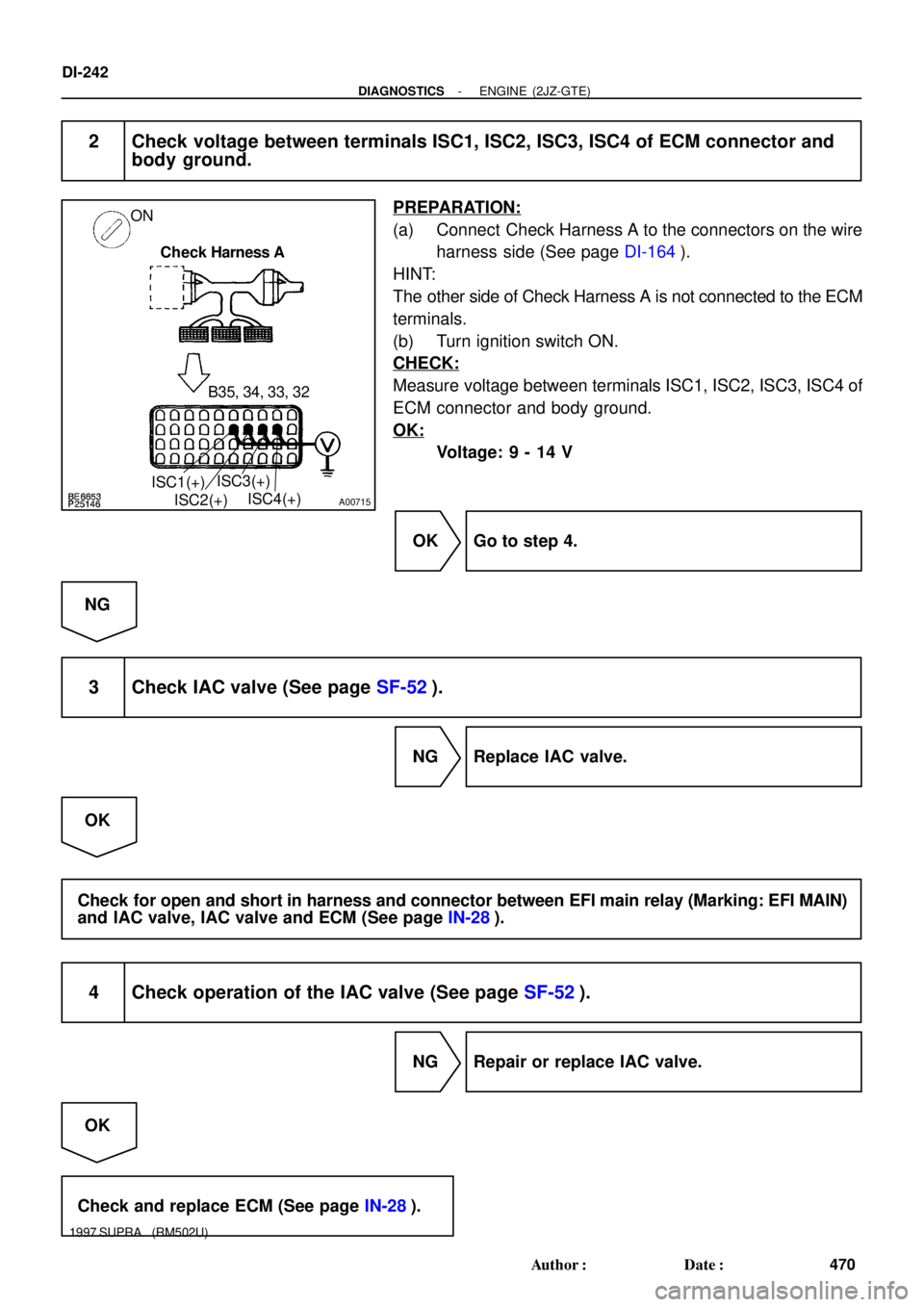
2 Check voltage between terminals ISC1, ISC2, ISC3, ISC4 of ECM connector and
body ground.
PREPARATION:
(a) Connect Check Harness A to the connectors on the wire
harness side (See page DI-164).
HINT:
The other side of Check Harness A is not connected to the ECM
terminals.
(b) Turn ignition switch ON.
CHECK:
Measure voltage between terminals ISC1, ISC2, ISC3, ISC4 of
ECM connector and body ground.
OK:
Voltage: 9 - 14 V
OK Go to step 4.
NG
3 Check IAC valve (See page SF-52).
NG Replace IAC valve.
OK
Check for open and short in harness and connector between EFI main relay (Marking: EFI MAIN)
and IAC valve, IAC valve and ECM (See page IN-28).
4 Check operation of the IAC valve (See page SF-52).
NG Repair or replace IAC valve.
OK
Check and replace ECM (See page IN-28).


A/C Switch ON \" OFF
(IAC Valve Close)
20 V/Division
20 V/Division ISC1
ISC2
ISC3
ISC4
ISC1
ISC2
ISC3
ISC4
10 msec./Division
10 msec./Division
- DIAGNOSTICSE")