Page 656 of 1807

DI-243
471 Author�: Date�:
1997 SUPRA (RM502U)
DTC P0510 Closed Throttle Position Switch Malfunction
CIRCUIT DESCRIPTION
Refer to ºThrottle/Pedal Position Sensor/Switc")
- DIAGNOSTICSENGINE (2JZ-GTE)
DI-243
471 Author�: Date�:
1997 SUPRA (RM502U)
DTC P0510 Closed Throttle Position Switch Malfunction
CIRCUIT DESCRIPTION
Refer to ºThrottle/Pedal Position Sensor/Switch ºAº Circuit Malfunctionº on page DI-184.
DTC No.DTC Detecting ConditionTrouble Area
P0510
The closed throttle position switch does not turn ON or OFF
even once when the vehicle is driven
(2 trip detection logic)�Open or short in closed throttle position switch circuit
�Closed throttle position switch
�ECM
HINT:
After confirming DTC P0510 use the TOYOTA hand-held tester to confirm the closed throttle position switch
signal from ºCURRENT DATAº.
Throttle ValveClosed throttle position switch signalMalfunction
Fully ClosedOFFOpen Circuit
Fully OpenONShort Circuit
WIRING DIAGRAM
Refer to page DI-184 for the WIRING DIAGRAM.
INSPECTION PROCEDURE
HINT:
If DTC P0110, P0115 and P0120 are output simultaneously, E2 (sensor ground) may be open.
TOYOTA hand-held tester
1 Connect the TOYOTA hand-held tester and read CTP switch signal.
PREPARATION:
(a) Connect the TOYOTA hand-held tester to the DLC3.
(b) Turn ignition switch ON and push the TOYOTA hand-held tester main switch ON.
CHECK:
Read CTP switch signal on the TOYOTA hand-held tester.
RESULT:
Throttle ValveClosed throttle position switch signalMalfunction
Fully ClosedOFFOpen Circuit: Go to step 2.
Fully OpenONOpen Circuit: Go to step 4.
DI4T9-01
Page 657 of 1807

BE6653
FI7058A00486
ON
Throttle Position
SensorECM
4
3
2
141
43
64
65B
B
B
B
VCC5V
VTA1
B+
IDL1
E2
A00716
ON
Throttle Position
Sensor
ECM
4
3
2
141
43
64
65
B
5V
IDL1
E2B B
VTA1
B+
BVCC
Check Harness A
ECM
B65, 64
IDL1 E2
DI-244
- DIAGNOSTICSENGINE (2JZ-GTE)
472 Author�: Date�:
1997 SUPRA (RM502U)
2 Check for open in harness or ECM.
PREPARATION:
(a) Connect the TOYOTA hand-held tester to the DLC3.
(b) Disconnect the throttle position sensor connector.
(c) Connect sensor wire harness terminals between termi-
nals 1 and 2.
(d) Turn ignition switch ON.
CHECK:
Read CTP switch signal on the TOYOTA hand-held tester.
OK:
CTP switch signal: ON
OK Confirm good connection at sensor.
If OK, replace throttle position sensor.
NG
3 Check for open in harness or ECM.
PREPARATION:
(a) Connect Check Harness A (See page DI-164).
(b) Connect between terminals IDL and E2 of ECM connec-
tor.
HINT:
Throttle position sensor connector is disconnected.
Before checking, do a visual check and contact pressure check
for the connector (See page IN-28).
(c) Turn ignition switch ON.
CHECK:
Read CTP switch signal on the TOYOTA hand-held tester.
OK:
CTP switch signal: ON
OK Open in harness between ECM and throttle
position sensor, repair or replace harness.
NG
Confirm connection at ECM.
If OK, replace ECM.
Page 658 of 1807

BE6653A00499A00488
ON
Throttle Position
SensorECM
4
3
2
141
43
64
65
B
5V
IDL1
E2B B
VTA1 B+
BVCC
A00717
ON
Throttle Position
Sensor
ECM
4
3
2
141
43
64
65
B
5V
IDL1
E2
BB
VTA1 B+
BVCC
ECM
B Connector
- DIAGNOSTICSENGINE (2JZ-GTE)
DI-245
473 Author�: Date�:
1997 SUPRA (RM502U)
4 Check for short in harness or ECM.
PREPARATION:
(a) Connect the TOYOTA hand-held tester to the DLC3.
(b) Disconnect the throttle position sensor connector.
(c) Turn ignition switch ON.
CHECK:
Read CTP switch signal on the TOYOTA hand-held tester.
OK:
CTP switch signal: OFF
OK Confirm good connection at sensor.
If OK, replace throttle position sensor.
NG
5 Check for short in harness or ECM.
PREPARATION:
(a) DIsconnect the B connector from ECM
(See page DI-164).
HINT:
Throttle position sensor connector is disconnected.
(b) Turn ignition switch ON.
CHECK:
Read CTP switch signal on the TOYOTA hand-held tester.
OK:
CTP switch signal: OFF
OK Short in harness between ECM and throttle
position sensor, repair or replace harness.
NG
Confirm connection at ECM.
If OK, replace ECM.
Page 659 of 1807
A00492
ON
Throttle Position
SensorECM
4
3
2(+)
1(-)41
43
64
65
B
5V
IDL1
E2
B B
VTA1
B+
BVCC
DI-246
- DIAGNOSTICSENGINE (2JZ-GTE)
474 Author�: Date�:
1997 SUPRA (RM502U)
OBDII scan tool (excluding TOYOTA hand-held tester)
1 Check for open and short in harness or ECM.
PREPARATION:
(a) Disconnect the throttle position sensor connector.
(b) Turn ignition switch ON.
CHECK:
Measure voltage between terminals 1 and 2 of throttle position
sensor connector.
OK:
Voltage: 9 - 14 V
OK Confirm good connection at sensor.
If OK, replace throttle position sensor.
NG
2 Check for open and short in harness and connector between throttle position
sensor and ECM (See page IN-28).
NG Open or short in harness between ECM and
throttle position sensor.
OK
Confirm connection at ECM.
If OK, replace ECM.
Page 660 of 1807

DI-215
443 Author�: Date�:
1997 SUPRA (RM502U)
DTC P0340 Camshaft Position Sensor Circuit
Malfunction
CIRCUIT DESCRIPTION
The camshaft position sens")
S03241S03242
A06719
- DIAGNOSTICSENGINE (2JZ-GTE)
DI-215
443 Author�: Date�:
1997 SUPRA (RM502U)
DTC P0340 Camshaft Position Sensor Circuit
Malfunction
CIRCUIT DESCRIPTION
The camshaft position sensors (G1 and G2 signals) consist of a signal plate and a pick up coil.
The G1, G2 signal plates each have one tooth on the outer circumference and are mounted on the intake
side of the cylinder head.
When the camshaft rotates, the protrusion on the signal plate and the air gap on the pick up coil change,
causing fluctuations in the magnetic field and generating an electromotive force in the pick up coil.
The ECM detects the standard crankshaft angle based on the G1, G2 signals, detects the actual crankshaft
angle and engine speed by the NE signals.
DTC No.DTC Detecting ConditionTrouble Area
P0340
No camshaft position sensor signal to ECM with engine speed
600 rpm or more�Open or short in camshaft position sensor circuit
�Camshaft position sensor
StarterP0340
No crankshaft position sensor signal to ECM during cranking
�Starter
�ECM
WIRING DIAGRAM
Refer to page DI-212 for the WIRING DIAGRAM.
INSPECTION PROCEDURE
1 Check resistance of camshaft position sensors.
PREPARATION:
Disconnect camshaft position sensor connector.
CHECK:
Measure resistance of camshaft position sensors.
OK:
Resistance
Cold835 - 1,400 W
Hot1,060 - 1,645 W
ºColdº is from - 10°C (14°F) to 50°C (122°F) and ºHotº is from
50°C (122°F) to 100°C (212°F).
DI4T2-01
Page 661 of 1807
FI6519A03396
G. NE Signal Waveforms
5 V/Division
20 m sec./Division (Idling) G1
G2
NE
DI-216
- DIAGNOSTICSENGINE (2JZ-GTE)
444 Author�: Date�:
1997 SUPRA (RM502U)
Reference INSPECTION USING OSCILLOSCOPE
�During cranking or idling, check between ECM terminals
G1, G2 and G1�, NE and NE� of ECM.
HINT:
The correct waveforms are as shown.
NG Replace distributor.
OK
2 Check for open and short in harness and connector between ECM and camshaft
position sensor (See page IN-28).
NG Repair or replace harness or connector.
OK
3 Inspection sensor installation.
NG Tighten the sensor.
OK
Check and replace ECM (See page IN-28).
Page 664 of 1807

BE6653S03247S03249
A03138
START
5 (+)
8 (-)
- DIAGNOSTICSENGINE (2JZ-GTE)
DI-249
477 Author�: Date�:
1997 SUPRA (RM502U)
INSPECTION PROCEDURE
1 Connect the TOYOTA h")
BE6653S03247S03248
A03137
ON
1(+)
BE6653S03247S03249
A03138
START
5 (+)
8 (-)
- DIAGNOSTICSENGINE (2JZ-GTE)
DI-249
477 Author�: Date�:
1997 SUPRA (RM502U)
INSPECTION PROCEDURE
1 Connect the TOYOTA hand-held tester and check operation of fuel pump
(See page SF-5).
OK Go to step 7.
NG
2 Check voltage of fuel pump ECU power source.
PREPARATION:
(a) Remove LH quarter trim panel (See page SF-83).
(b) Disconnect fuel pump ECU connector.
(c) Turn ignition switch ON.
CHECK:
Measure voltage between terminal 1 of fuel pump ECU connec-
tor and body ground.
OK:
Voltage: 9 - 14 V
NG Check for open and short in harness and con-
nector between EFI main relay (Marking: EFI
MAIN) and fuel pump ECU (See page IN-28).
OK
3 Check voltage between terminals 5 and 8 of fuel pump ECU connector.
PREPARATION:
(a) Remove LH quarter trim panel (See page SF-83).
(b) Disconnect fuel pump ECU connector.
CHECK:
Measure voltage between terminals 5 and 8 of fuel pump ECU
connector when ignition switch is turned to start.
OK:
Voltage: 4.5 - 5.5 V
OK Go to step 5.
NG
Page 665 of 1807
DI-250
- DIAGNOSTICSENGINE (2JZ-GTE)
478 Author�: Date�:
1997 SUPRA (RM502U)
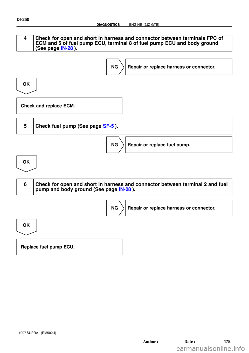
4 Check for open and short in harness and connector between terminals FPC of
ECM and 5 of fuel pump ECU, terminal 8 of fuel pump ECU and body ground
(See page IN-28).
NG Repair or replace harness or connector.
OK
Check and replace ECM.
5 Check fuel pump (See page SF-5).
NG Repair or replace fuel pump.
OK
6 Check for open and short in harness and connector between terminal 2 and fuel
pump and body ground (See page IN-28).
NG Repair or replace harness or connector.
OK
Replace fuel pump ECU.