1997 SSANGYONG KORANDO battery
[x] Cancel search: batteryPage 1652 of 2053
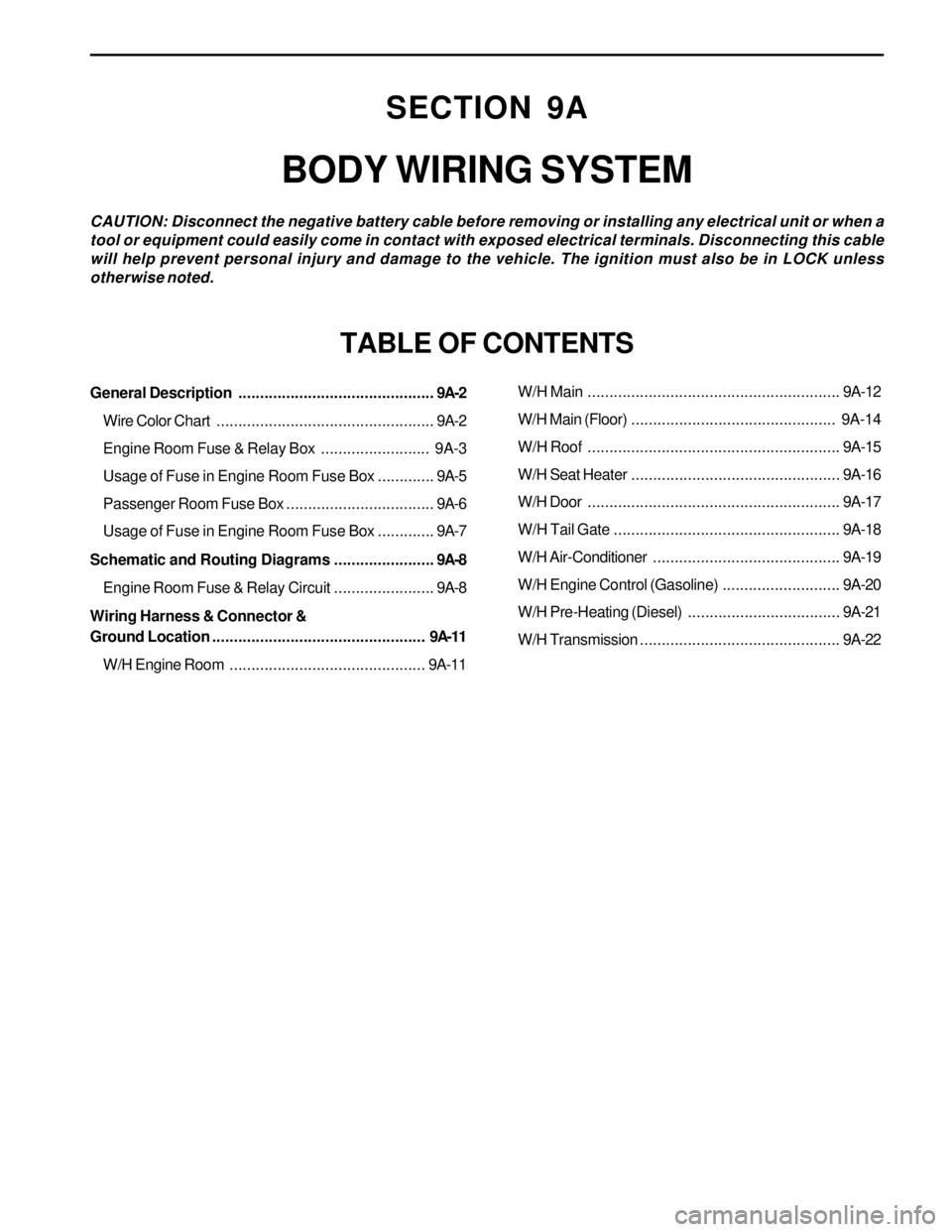
SECTION 9A
BODY WIRING SYSTEM
CAUTION: Disconnect the negative battery cable before removing or installing any electrical unit or when a
tool or equipment could easily come in contact with exposed electrical terminals. Disconnecting this cable
will help prevent personal injury and damage to the vehicle. The ignition must also be in LOCK unless
otherwise noted.
TABLE OF CONTENTS
General Description.............................................9A-2
Wire Color Chart..................................................9A-2
Engine Room Fuse & Relay Box......................... 9A-3
Usage of Fuse in Engine Room Fuse Box.............9A-5
Passenger Room Fuse Box..................................9A-6
Usage of Fuse in Engine Room Fuse Box.............9A-7
Schematic and Routing Diagrams.......................9A-8
Engine Room Fuse & Relay Circuit.......................9A-8
Wiring Harness & Connector &
Ground Location................................................. 9A-11
W/H Engine Room.............................................9A-11W/H Main..........................................................9A-12
W/H Main (Floor)............................................... 9A-14
W/H Roof..........................................................9A-15
W/H Seat Heater................................................9A-16
W/H Door..........................................................9A-17
W/H Tail Gate....................................................9A-18
W/H Air-Conditioner...........................................9A-19
W/H Engine Control (Gasoline)...........................9A-20
W/H Pre-Heating (Diesel)...................................9A-21
W/H Transmission..............................................9A-22
Page 1656 of 2053
BODY WIRING SYSTEM 9A-5
SSANGYONG MY2002
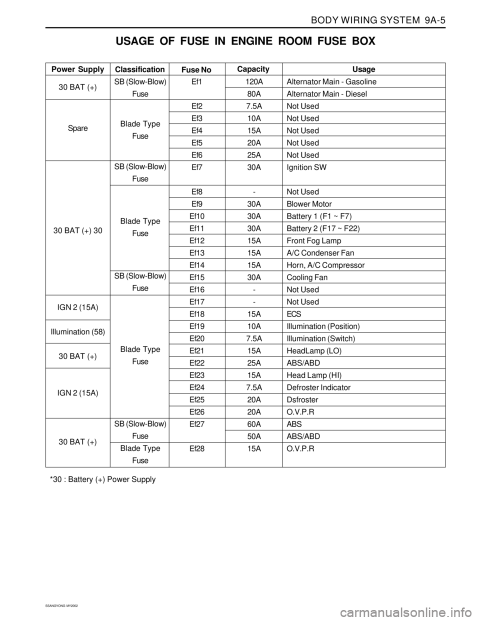
USAGE OF FUSE IN ENGINE ROOM FUSE BOX
Alternator Main - Gasoline
Alternator Main - Diesel
Not Used
Not Used
Not Used
Not Used
Not Used
Ignition SW
Not Used
Blower Motor
Battery 1 (F1 ~ F7)
Battery 2 (F17 ~ F22)
Front Fog Lamp
A/C Condenser Fan
Horn, A/C Compressor
Cooling Fan
Not Used
Not Used
ECS
Illumination (Position)
Illumination (Switch)
HeadLamp (LO)
ABS/ABD
Head Lamp (HI)
Defroster Indicator
Dsfroster
O.V.P.R
ABS
ABS/ABD
O.V.P.R Power SupplyUsage
Classification
Fuse NoCapacity
30 BAT (+)
Spare
30 BAT (+) 30
IGN 2 (15A)
Illumination (58)
30 BAT (+)
IGN 2 (15A)
30 BAT (+)SB (Slow-Blow)
Fuse
Blade Type
Fuse
SB (Slow-Blow)
Fuse
Blade Type
Fuse
SB (Slow-Blow)
Fuse
Blade Type
Fuse
SB (Slow-Blow)
Fuse
Blade Type
FuseEf1
Ef2
Ef3
Ef4
Ef5
Ef6
Ef7
Ef8
Ef9
Ef10
Ef11
Ef12
Ef13
Ef14
Ef15
Ef16
Ef17
Ef18
Ef19
Ef20
Ef21
Ef22
Ef23
Ef24
Ef25
Ef26
Ef27
Ef28120A
80A
7.5A
10A
15A
20A
25A
30A
-
30A
30A
30A
15A
15A
15A
30A
-
-
15A
10A
7.5A
15A
25A
15A
7.5A
20A
20A
60A
50A
15A
*30 : Battery (+) Power Supply
Page 1658 of 2053
BODY WIRING SYSTEM 9A-7
SSANGYONG MY2002
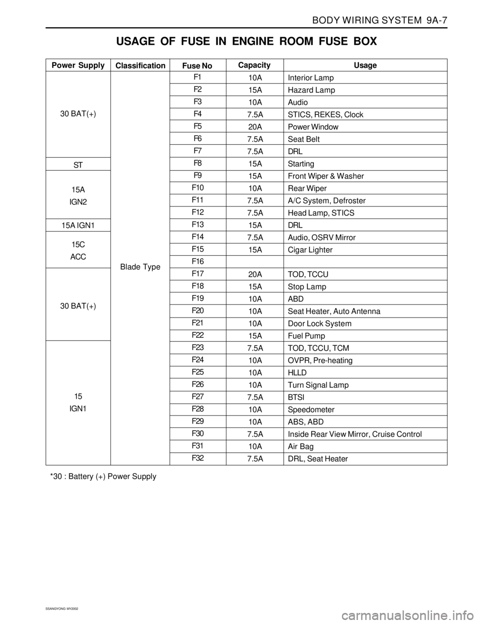
USAGE OF FUSE IN ENGINE ROOM FUSE BOX
Interior Lamp
Hazard Lamp
Audio
STICS, REKES, Clock
Power Window
Seat Belt
DRL
Starting
Front Wiper & Washer
Rear Wiper
A/C System, Defroster
Head Lamp, STICS
DRL
Audio, OSRV Mirror
Cigar Lighter
TOD, TCCU
Stop Lamp
ABD
Seat Heater, Auto Antenna
Door Lock System
Fuel Pump
TOD, TCCU, TCM
OVPR, Pre-heating
HLLD
Turn Signal Lamp
BTSI
Speedometer
ABS, ABD
Inside Rear View Mirror, Cruise Control
Air Bag
DRL, Seat Heater Power SupplyUsage
Classification
Fuse NoCapacity
30 BAT(+)
ST
15A
IGN2
15A IGN1
15C
ACC
30 BAT(+)
15
IGN1
Blade TypeF1
F2
F3
F4
F5
F6
F7
F8
F9
F10
F11
F12
F13
F14
F15
F16
F17
F18
F19
F20
F21
F22
F23
F24
F25
F26
F27
F28
F29
F30
F31
F3210A
15A
10A
7.5A
20A
7.5A
7.5A
15A
15A
10A
7.5A
7.5A
15A
7.5A
15A
20A
15A
10A
10A
10A
15A
7.5A
10A
10A
10A
7.5A
10A
10A
7.5A
10A
7.5A
*30 : Battery (+) Power Supply
Page 1675 of 2053
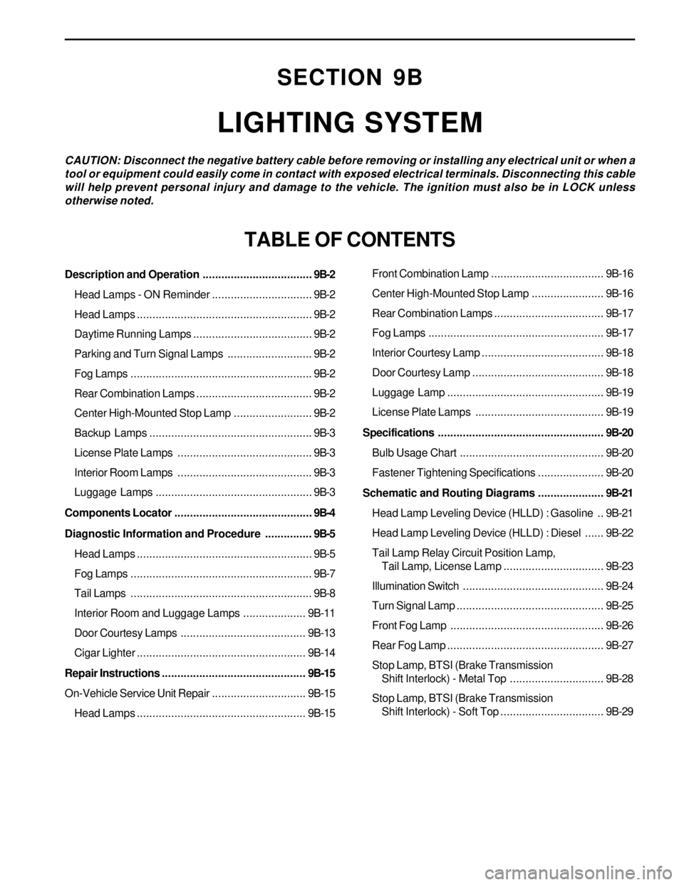
SECTION 9B
LIGHTING SYSTEM
CAUTION: Disconnect the negative battery cable before removing or installing any electrical unit or when a
tool or equipment could easily come in contact with exposed electrical terminals. Disconnecting this cable
will help prevent personal injury and damage to the vehicle. The ignition must also be in LOCK unless
otherwise noted.
TABLE OF CONTENTS
Description and Operation...................................9B-2
Head Lamps - ON Reminder................................9B-2
Head Lamps........................................................9B-2
Daytime Running Lamps......................................9B-2
Parking and Turn Signal Lamps...........................9B-2
Fog Lamps..........................................................9B-2
Rear Combination Lamps.....................................9B-2
Center High-Mounted Stop Lamp.........................9B-2
Backup Lamps....................................................9B-3
License Plate Lamps ...........................................9B-3
Interior Room Lamps ...........................................9B-3
Luggage Lamps..................................................9B-3
Components Locator............................................9B-4
Diagnostic Information and Procedure...............9B-5
Head Lamps........................................................9B-5
Fog Lamps..........................................................9B-7
Tail Lamps..........................................................9B-8
Interior Room and Luggage Lamps....................9B-11
Door Courtesy Lamps ........................................9B-13
Cigar Lighter......................................................9B-14
Repair Instructions..............................................9B-15
On-Vehicle Service Unit Repair..............................9B-15
Head Lamps......................................................9B-15Front Combination Lamp....................................9B-16
Center High-Mounted Stop Lamp.......................9B-16
Rear Combination Lamps...................................9B-17
Fog Lamps........................................................9B-17
Interior Courtesy Lamp .......................................9B-18
Door Courtesy Lamp ..........................................9B-18
Luggage Lamp..................................................9B-19
License Plate Lamps .........................................9B-19
Specifications.....................................................9B-20
Bulb Usage Chart..............................................9B-20
Fastener Tightening Specifications.....................9B-20
Schematic and Routing Diagrams.....................9B-21
Head Lamp Leveling Device (HLLD) : Gasoline ..9B-21
Head Lamp Leveling Device (HLLD) : Diesel......9B-22
Tail Lamp Relay Circuit Position Lamp,
Tail Lamp, License Lamp................................9B-23
Illumination Switch.............................................9B-24
Turn Signal Lamp...............................................9B-25
Front Fog Lamp.................................................9B-26
Rear Fog Lamp..................................................9B-27
Stop Lamp, BTSI (Brake Transmission
Shift Interlock) - Metal Top..............................9B-28
Stop Lamp, BTSI (Brake Transmission
Shift Interlock) - Soft Top.................................9B-29
Page 1679 of 2053
LIGHTING SYSTEM 9B-5
SSANGYONG MY2002
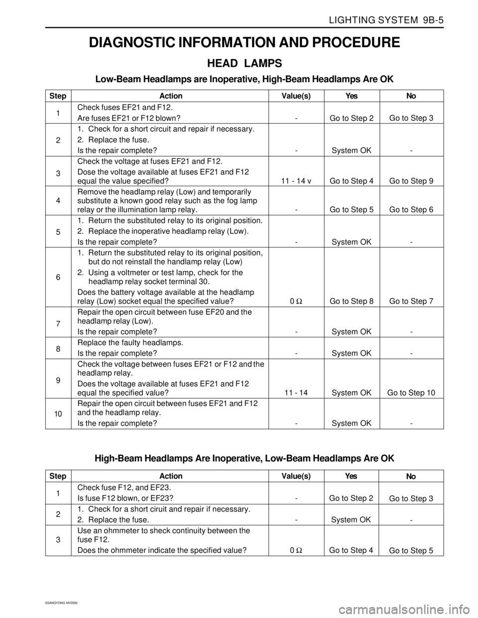
DIAGNOSTIC INFORMATION AND PROCEDURE
HEAD LAMPS
Low-Beam Headlamps are Inoperative, High-Beam Headlamps Are OK
Step
1
2
3
4
5
6
7
8
9
10Action
Check fuses EF21 and F12.
Are fuses EF21 or F12 blown?
1. Check for a short circuit and repair if necessary.
2. Replace the fuse.
Is the repair complete?
Check the voltage at fuses EF21 and F12.
Dose the voltage available at fuses EF21 and F12
equal the value specified?
Remove the headlamp relay (Low) and temporarily
substitute a known good relay such as the fog lamp
relay or the illumination lamp relay.
1. Return the substituted relay to its original position.
2. Replace the inoperative headlamp relay (Low).
Is the repair complete?
1. Return the substituted relay to its original position,
but do not reinstall the handlamp relay (Low)
2. Using a voltmeter or test lamp, check for the
headlamp relay socket terminal 30.
Does the battery voltage available at the headlamp
relay (Low) socket equal the specified value?
Repair the open circuit between fuse EF20 and the
headlamp relay (Low).
Is the repair complete?
Replace the faulty headlamps.
Is the repair complete?
Check the voltage between fuses EF21 or F12 and the
headlamp relay.
Does the voltage available at fuses EF21 and F12
equal the specified value?
Repair the open circuit between fuses EF21 and F12
and the headlamp relay.
Is the repair complete?Yes
Go to Step 2
System OK
Go to Step 4
Go to Step 5
System OK
Go to Step 8
System OK
System OK
System OK
System OKNo
Go to Step 3
-
Go to Step 9
Go to Step 6
-
Go to Step 7
-
-
Go to Step 10
- Value(s)
-
-
11 - 14 v
-
-
0 Ω
-
-
11 - 14
-
High-Beam Headlamps Are Inoperative, Low-Beam Headlamps Are OK
Step
1
2
3Action
Check fuse F12, and EF23.
Is fuse F12 blown, or EF23?
1. Check for a short ciruit and repair if necessary.
2. Replace the fuse.
Use an ohmmeter to sheck continuity between the
fuse F12.
Does the ohmmeter indicate the specified value?Yes
Go to Step 2
System OK
Go to Step 4No
Go to Step 3
-
Go to Step 5 Value(s)
-
-
0 Ω
Page 1681 of 2053
LIGHTING SYSTEM 9B-7
SSANGYONG MY2002
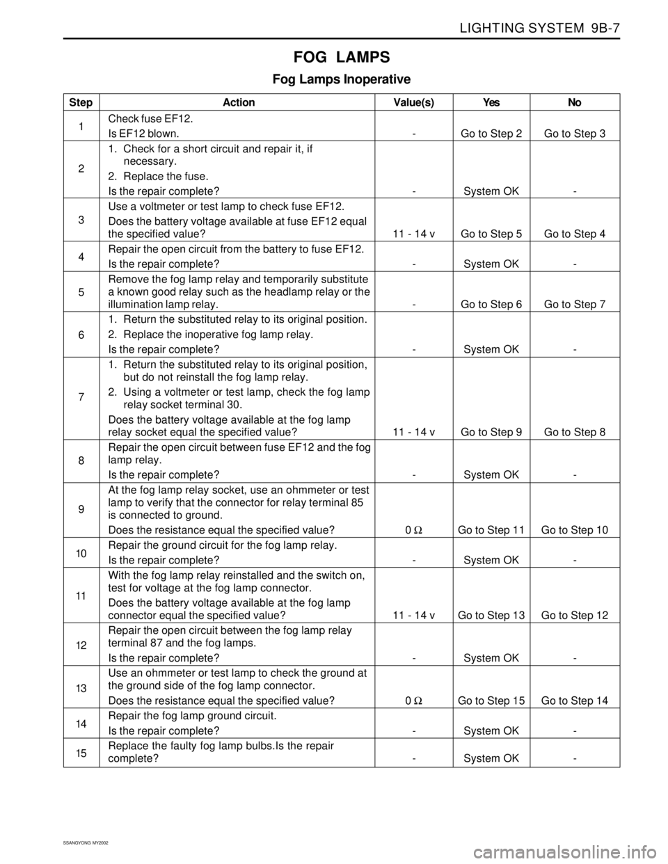
Step
1
2
3
4
5
6
7
8
9
10
11
12
13
14
15Action
Check fuse EF12.
Is EF12 blown.
1. Check for a short circuit and repair it, if
necessary.
2. Replace the fuse.
Is the repair complete?
Use a voltmeter or test lamp to check fuse EF12.
Does the battery voltage available at fuse EF12 equal
the specified value?
Repair the open circuit from the battery to fuse EF12.
Is the repair complete?
Remove the fog lamp relay and temporarily substitute
a known good relay such as the headlamp relay or the
illumination lamp relay.
1. Return the substituted relay to its original position.
2. Replace the inoperative fog lamp relay.
Is the repair complete?
1. Return the substituted relay to its original position,
but do not reinstall the fog lamp relay.
2. Using a voltmeter or test lamp, check the fog lamp
relay socket terminal 30.
Does the battery voltage available at the fog lamp
relay socket equal the specified value?
Repair the open circuit between fuse EF12 and the fog
lamp relay.
Is the repair complete?
At the fog lamp relay socket, use an ohmmeter or test
lamp to verify that the connector for relay terminal 85
is connected to ground.
Does the resistance equal the specified value?
Repair the ground circuit for the fog lamp relay.
Is the repair complete?
With the fog lamp relay reinstalled and the switch on,
test for voltage at the fog lamp connector.
Does the battery voltage available at the fog lamp
connector equal the specified value?
Repair the open circuit between the fog lamp relay
terminal 87 and the fog lamps.
Is the repair complete?
Use an ohmmeter or test lamp to check the ground at
the ground side of the fog lamp connector.
Does the resistance equal the specified value?
Repair the fog lamp ground circuit.
Is the repair complete?
Replace the faulty fog lamp bulbs.Is the repair
complete?Yes
Go to Step 2
System OK
Go to Step 5
System OK
Go to Step 6
System OK
Go to Step 9
System OK
Go to Step 11
System OK
Go to Step 13
System OK
Go to Step 15
System OK
System OKNo
Go to Step 3
-
Go to Step 4
-
Go to Step 7
-
Go to Step 8
-
Go to Step 10
-
Go to Step 12
-
Go to Step 14
-
- Value(s)
-
-
11 - 14 v
-
-
-
11 - 14 v
-
0 Ω
-
11 - 14 v
-
0 Ω
-
-
FOG LAMPS
Fog Lamps Inoperative
Page 1682 of 2053
SSANGYONG MY2002
9B-8 LIGHTING SYSTEM
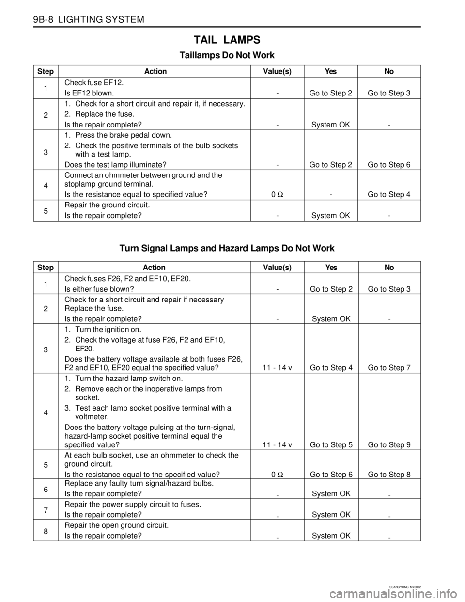
Turn Signal Lamps and Hazard Lamps Do Not Work
Step
1
2
3
4
5
6
7
8Action
Check fuses F26, F2 and EF10, EF20.
Is either fuse blown?
Check for a short circuit and repair if necessary
Replace the fuse.
Is the repair complete?
1. Turn the ignition on.
2. Check the voltage at fuse F26, F2 and EF10,
EF20.
Does the battery voltage available at both fuses F26,
F2 and EF10, EF20 equal the specified value?
1. Turn the hazard lamp switch on.
2. Remove each or the inoperative lamps from
socket.
3. Test each lamp socket positive terminal with a
voltmeter.
Does the battery voltage pulsing at the turn-signal,
hazard-lamp socket positive terminal equal the
specified value?
At each bulb socket, use an ohmmeter to check the
ground circuit.
Is the resistance equal to the specified value?
Replace any faulty turn signal/hazard bulbs.
Is the repair complete?
Repair the power supply circuit to fuses.
Is the repair complete?
Repair the open ground circuit.
Is the repair complete?Yes
Go to Step 2
System OK
Go to Step 4
Go to Step 5
Go to Step 6
System OK
System OK
System OKNo
Go to Step 3
-
Go to Step 7
Go to Step 9
Go to Step 8
-
-
- Value(s)
-
-
11 - 14 v
11 - 14 v
0 Ω
-
-
-
TAIL LAMPS
Taillamps Do Not Work
Step
1
2
3
4
5Action
Check fuse EF12.
Is EF12 blown.
1. Check for a short circuit and repair it, if necessary.
2. Replace the fuse.
Is the repair complete?
1. Press the brake pedal down.
2. Check the positive terminals of the bulb sockets
with a test lamp.
Does the test lamp illuminate?
Connect an ohmmeter between ground and the
stoplamp ground terminal.
Is the resistance equal to specified value?
Repair the ground circuit.
Is the repair complete?Yes
Go to Step 2
System OK
Go to Step 2
-
System OKNo
Go to Step 3
-
Go to Step 6
Go to Step 4
- Value(s)
-
-
-
0 Ω
-
Page 1683 of 2053
LIGHTING SYSTEM 9B-9
SSANGYONG MY2002
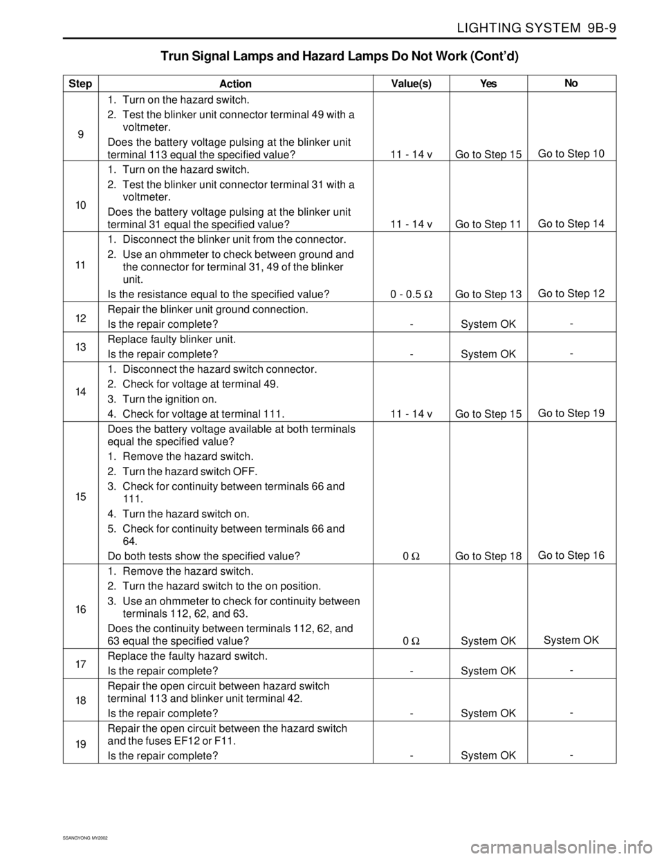
Trun Signal Lamps and Hazard Lamps Do Not Work (Cont’d)
Step
9
10
11
12
13
14
15
16
17
18
19Action
1. Turn on the hazard switch.
2. Test the blinker unit connector terminal 49 with a
voltmeter.
Does the battery voltage pulsing at the blinker unit
terminal 113 equal the specified value?
1. Turn on the hazard switch.
2. Test the blinker unit connector terminal 31 with a
voltmeter.
Does the battery voltage pulsing at the blinker unit
terminal 31 equal the specified value?
1. Disconnect the blinker unit from the connector.
2. Use an ohmmeter to check between ground and
the connector for terminal 31, 49 of the blinker
unit.
Is the resistance equal to the specified value?
Repair the blinker unit ground connection.
Is the repair complete?
Replace faulty blinker unit.
Is the repair complete?
1. Disconnect the hazard switch connector.
2. Check for voltage at terminal 49.
3. Turn the ignition on.
4. Check for voltage at terminal 111.
Does the battery voltage available at both terminals
equal the specified value?
1. Remove the hazard switch.
2. Turn the hazard switch OFF.
3. Check for continuity between terminals 66 and
111.
4. Turn the hazard switch on.
5. Check for continuity between terminals 66 and
64.
Do both tests show the specified value?
1. Remove the hazard switch.
2. Turn the hazard switch to the on position.
3. Use an ohmmeter to check for continuity between
terminals 112, 62, and 63.
Does the continuity between terminals 112, 62, and
63 equal the specified value?
Replace the faulty hazard switch.
Is the repair complete?
Repair the open circuit between hazard switch
terminal 113 and blinker unit terminal 42.
Is the repair complete?
Repair the open circuit between the hazard switch
and the fuses EF12 or F11.
Is the repair complete?Yes
Go to Step 15
Go to Step 11
Go to Step 13
System OK
System OK
Go to Step 15
Go to Step 18
System OK
System OK
System OK
System OKNo
Go to Step 10
Go to Step 14
Go to Step 12
-
-
Go to Step 19
Go to Step 16
System OK
-
-
- Value(s)
11 - 14 v
11 - 14 v
0 - 0.5 Ω
-
-
11 - 14 v
0 Ω
0 Ω
-
-
-