1997 SSANGYONG KORANDO battery
[x] Cancel search: batteryPage 1692 of 2053
SSANGYONG MY2002
9B-18 LIGHTING SYSTEM
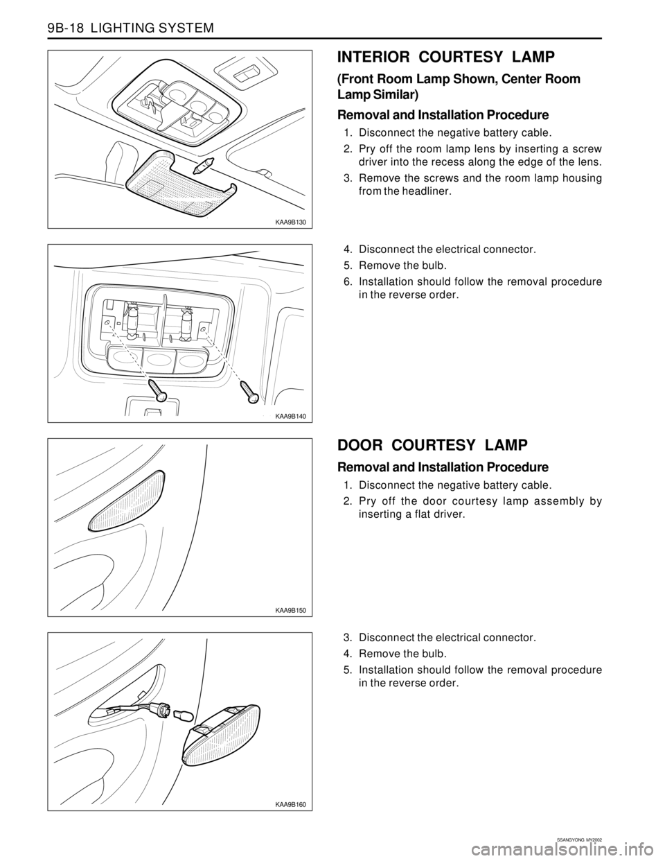
KAA9B130
KAA9B140
4. Disconnect the electrical connector.
5. Remove the bulb.
6. Installation should follow the removal procedure
in the reverse order.
INTERIOR COURTESY LAMP
(Front Room Lamp Shown, Center Room
Lamp Similar)
Removal and Installation Procedure
1. Disconnect the negative battery cable.
2. Pry off the room lamp lens by inserting a screw
driver into the recess along the edge of the lens.
3. Remove the screws and the room lamp housing
from the headliner.
KAA9B160
3. Disconnect the electrical connector.
4. Remove the bulb.
5. Installation should follow the removal procedure
in the reverse order.
KAA9B150
DOOR COURTESY LAMP
Removal and Installation Procedure
1. Disconnect the negative battery cable.
2. Pry off the door courtesy lamp assembly by
inserting a flat driver.
Page 1693 of 2053
LIGHTING SYSTEM 9B-19
SSANGYONG MY2002
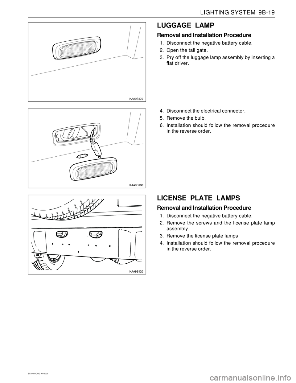
KAA9B170
KAA9B180
4. Disconnect the electrical connector.
5. Remove the bulb.
6. Installation should follow the removal procedure
in the reverse order.
LUGGAGE LAMP
Removal and Installation Procedure
1. Disconnect the negative battery cable.
2. Open the tail gate.
3. Pry off the luggage lamp assembly by inserting a
flat driver.
KAA9B120
LICENSE PLATE LAMPS
Removal and Installation Procedure
1. Disconnect the negative battery cable.
2. Remove the screws and the license plate lamp
assembly.
3. Remove the license plate lamps
4. Installation should follow the removal procedure
in the reverse order.
Page 1704 of 2053
SECTION 9C
HORNS
CAUTION: Disconnect the negative battery cable before removing or installing any electrical unit or when a
tool or equipment could easily come in contact with exposed electrical terminals. Disconnecting this cable
will help prevent personal injury and damage to the vehicle. The ignition must also be in LOCK unless
otherwise noted.
TABLE OF CONTENTS
Description and Operation.................................. 9C-2
Horns ................................................................. 9C-2
Components Locator ........................................... 9C-3
Lighting System................................................. 9C-3Repair Instructions............................................... 9C-4
On-Vehice Service Unit Repair............................... 9C-4
Dual Horns......................................................... 9C-4
Schematic and Routing Diagram....................... 9C-5
Horn Wiring System............................................ 9C-5
Page 1707 of 2053
SSANGYONG MY2002
9C-4 HORNS
REPAIR INSTRUCTIONS
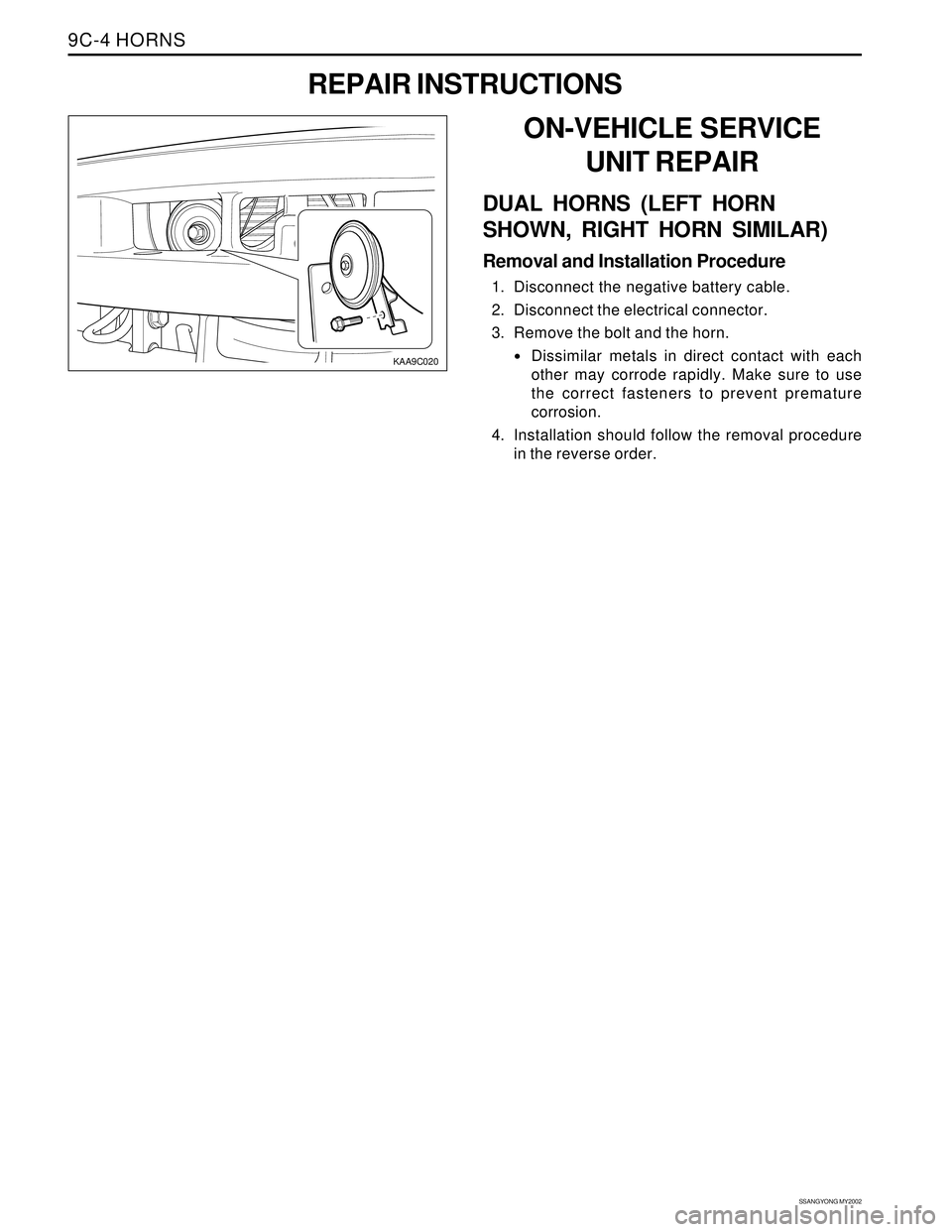
KAA9C020
ON-VEHICLE SERVICE
UNIT REPAIR
DUAL HORNS (LEFT HORN
SHOWN, RIGHT HORN SIMILAR)
Removal and Installation Procedure
1. Disconnect the negative battery cable.
2. Disconnect the electrical connector.
3. Remove the bolt and the horn.
Dissimilar metals in direct contact with each
other may corrode rapidly. Make sure to use
the correct fasteners to prevent premature
corrosion.
4. Installation should follow the removal procedure
in the reverse order.
Page 1709 of 2053
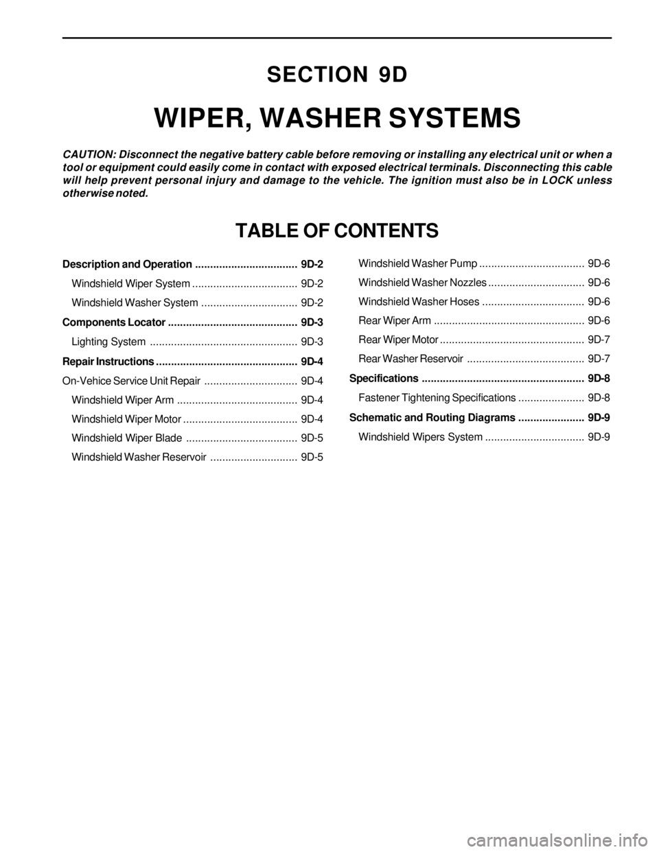
Description and Operation.................................. 9D-2
Windshield Wiper System................................... 9D-2
Windshield Washer System................................ 9D-2
Components Locator ........................................... 9D-3
Lighting System................................................. 9D-3
Repair Instructions............................................... 9D-4
On-Vehice Service Unit Repair............................... 9D-4
Windshield Wiper Arm........................................ 9D-4
Windshield Wiper Motor...................................... 9D-4
Windshield Wiper Blade..................................... 9D-5
Windshield Washer Reservoir............................. 9D-5
SECTION 9D
WIPER, WASHER SYSTEMS
CAUTION: Disconnect the negative battery cable before removing or installing any electrical unit or when a
tool or equipment could easily come in contact with exposed electrical terminals. Disconnecting this cable
will help prevent personal injury and damage to the vehicle. The ignition must also be in LOCK unless
otherwise noted.
TABLE OF CONTENTS
Windshield Washer Pump................................... 9D-6
Windshield Washer Nozzles................................ 9D-6
Windshield Washer Hoses.................................. 9D-6
Rear Wiper Arm.................................................. 9D-6
Rear Wiper Motor................................................ 9D-7
Rear Washer Reservoir....................................... 9D-7
Specifications...................................................... 9D-8
Fastener Tightening Specifications...................... 9D-8
Schematic and Routing Diagrams...................... 9D-9
Windshield Wipers System................................. 9D-9
Page 1713 of 2053
WIPER, WASHER SYSTEMS 9D-5
SSANGYONG MY2002
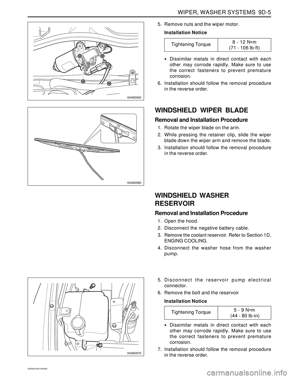
KAA9D050
KAA9D060
5. Remove nuts and the wiper motor.
Installation Notice
Dissimilar metals in direct contact with each
other may corrode rapidly. Make sure to use
the correct fasteners to prevent premature
corrosion.
6. Installation should follow the removal procedure
in the reverse order.
WINDSHIELD WASHER
RESERVOIR
Removal and Installation Procedure
1. Open the hood.
2. Disconnect the negative battery cable.
3. Remove the coolant reservoir. Refer to Section 1D,
ENGING COOLING.
4. Disconnect the washer hose from the washer
pump.
WINDSHIELD WIPER BLADE
Removal and Installation Procedure
1. Rotate the wiper blade on the arm.
2. While pressing the retainer clip, slide the wiper
blade down the wiper arm and remove the blade.
3. Installation should follow the removal procedure
in the reverse order.
Tightening Torque8 - 12 Nm
(71 - 106 lb-ft)
KAA9D070
5. Disconnect the reservoir pump electrical
connector.
6. Remove the bolt and the reservoir
Installation Notice
Dissimilar metals in direct contact with each
other may corrode rapidly. Make sure to use
the correct fasteners to prevent premature
corrosion.
7. Installation should follow the removal procedure
in the reverse order.
Tightening Torque5 - 9 Nm
(44 - 80 lb-in)
Page 1718 of 2053

SECTION 9E
INSTRUMENTATION, DRIVER INFORMATION
CAUTION: Disconnect the negative battery cable before removing or installing any electrical unit or when a
tool or equipment could easily come in contact with exposed electrical terminals. Disconnecting this cable
will help prevent personal injury and damage to the vehicle. The ignition must also be in LOCK unless
otherwise noted.
TABLE OF CONTENTS
Description and Operation.................................. 9E-2
Cigar Lighter....................................................... 9E-2
Ashtray.............................................................. 9E-2
Instrument Panel Vents....................................... 9E-2
Glove Box.......................................................... 9E-2
Digital Clock....................................................... 9E-2
Instrument Cluster.............................................. 9E-2
Speedometer and Tachometer............................ 9E-2
Trip Odometer.................................................... 9E-2
Fuel Gauge......................................................... 9E-2
Temperature Gauge............................................ 9E-2
Instrument Cluster Indicator Lamps..................... 9E-2
Chime Module.................................................... 9E-2
Components Locator ........................................... 9E-3
Instrumentation/Driver Information....................... 9E-3
Diagnostic Information and Procedure.............. 9E-5
Cigar Lighter....................................................... 9E-5
Disital Clock....................................................... 9E-5
Speedo Meter..................................................... 9E-6
Fuel Gauge......................................................... 9E-7
Temperature Gauge............................................ 9E-8
Instrument Cluster Indicator Lamps..................... 9E-9
Repair Instructions............................................. 9E-10
On-Vehice Service Unit Repair............................. 9E-10
Center Tray....................................................... 9E-10
Center Facia..................................................... 9E-10
Ashtray............................................................ 9E-10
Cigar Lighter..................................................... 9E-11Cup Holder....................................................... 9E-11
Instrument Panel Vent....................................... 9E-11
Glove Box........................................................ 9E-12
Chime Module.................................................. 9E-12
Hood Latch Release Handle.............................. 9E-12
Instrument Lower Cover.................................... 9E-13
Instrument Cluster Trim Panel........................... 9E-13
Instrument Cluster............................................ 9E-13
Speedometer/Odometer/Trip Odometer/
Tachometer................................................... 9E-14
Fuel Gauge....................................................... 9E-14
Temperature Gauge .......................................... 9E-15
Digital Clock..................................................... 9E-15
Instrument Cluster Indicator Lamps................... 9E-15
Instrument Panel............................................... 9E-16
Specifications.................................................... 9E-18
Bulb Usage Chart............................................. 9E-18
Schematic and Routing Diagram..................... 9E-19
Instrument Panel Illumination............................ 9E-19
Cluster (VSS, Meter & Gauge): Diesel.................9E-20
Cluster (VSS, Meter & Gauge): Gasoline............ 9E-21
Warning Lamp, TCS Indicator........................... 9E-22
Indicator........................................................... 9E-23
Warning Lamp.................................................. 9E-24
Digital Clock, Warning Cluster Illumination......... 9E-25
Selector Lever Position Lamp............................ 9E-26
Page 1722 of 2053
INSTRUMENTATION, DRIVER INFORMATION 9E-5
SSANGYONG MY2002
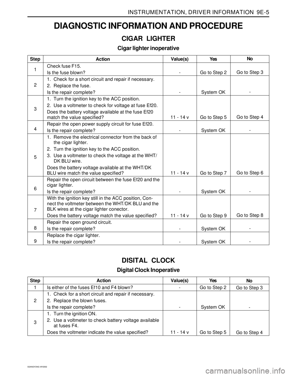
DIAGNOSTIC INFORMATION AND PROCEDURE
CIGAR LIGHTER
Cigar lighter inoperative
Step
1
2
3
4
5
6
7
8
9Action
Check fuse F15.
Is the fuse blown?
1. Check for a short circuit and repair if necessary.
2. Replace the fuse.
Is the repair complete?
1. Turn the ignition key to the ACC position.
2. Use a voltmeter to check for voltage at fuse Ef20.
Does the battery voltage available at the fuse Ef20
match the value specified?
Repair the open power supply circuit for fuse Ef20.
Is the repair complete?
1. Remove the electrical connector from the back of
the cigar lighter.
2. Turn the ignition key to the ACC position.
3. Use a voltmeter to check the voltage at the WHT/
DK BLU wire.
Does the battery voltage available at the WHT/DK
BLU wire match the value specified?
Repair the open circuit between the fuse Ef20 and the
cigar lighter.
Is the repair complete?
With the ignition key still in the ACC position, Con-
nect the voltmeter between the WHT/DK BLU and the
BLK wires at the cigar lighter conector.
Does the battery voltage match the value specified?
Repair the open ground circuit.
Is the repair complete?
Replace the cigar lighter.
Is the repair complete?Yes
Go to Step 2
System OK
Go to Step 5
System OK
Go to Step 7
System OK
Go to Step 9
System OK
System OKNo
Go to Step 3
-
Go to Step 4
-
Go to Step 6
-
Go to Step 8
-
- Value(s)
-
-
11 - 14 v
-
11 - 14 v
-
11 - 14 v
-
-
DISITAL CLOCK
Digital Clock Inoperative
Step
1
2
3Action
Is either of the fuses Ef10 and F4 blown?
1. Check for a short circuit and repair if necessary.
2. Replace the blown fuses.
Is the repair complete?
1. Turn the ignition ON.
2. Use a voltmeter to check battery voltage available
at fuses F4.
Does the voltmeter indicate the value specified?Yes
Go to Step 2
System OK
Go to Step 5No
Go to Step 3
-
Go to Step 4 Value(s)
-
-
11 - 14 v