Page 1748 of 2053
AUDIO SYSTEM 9F-5
SSANGYONG MY2002
KAA9F060
KAA9F050
MAST ANTENNA
Removal and Installation Procedure
1. Disconnect the negative battery cable.
2. Remove the center high-mounted stop lamp cover
3. Disconnect the CHMSL electrical connector.
4. Remove the screws with the CHMSL.
5. Installation should follow the removal procedure
in the reverse order.
REAR SPEAKERS
Removal and Installation Procedure
1. Disconnect the negative battery cable.
2. Remove the quarter trim panel. Refer to Section
9G, Interior Trim.
3. Installation should follow the removal procedure
in the reverse order.
Page 1750 of 2053

Description and Operation..................................9G-2
Interior Trim Panels.............................................9G-2
Floor Console.....................................................9G-2
Floor Carpet........................................................9G-2
Components Locator ...........................................9G-3
Interior Trim........................................................9G-3
Repair Instructions...............................................9G-4
On-Vehicle Service Unit Repair...............................9G-4
Door Trim Panel..................................................9G-4
SECTION 9G
INTERIOR TRIM
CAUTION: Disconnect the negative battery cable before removing or installing any electrical unit or when a
tool or equipment could easily come in contact with exposed electrical terminals. Disconnecting this cable
will help prevent personal injury and damage to the vehicle. The ignition must also be in LOCK unless
otherwise noted.
TABLE OF CONTENTS
A-Pillar Trim Panel...............................................9G-5
Upper Quarter Trim Panel....................................9G-5
Lower Quarter Trim Panel....................................9G-6
Cowl Side Trim Panel ..........................................9G-6
Front Rocker Trim Panel......................................9G-7
Floor Console.....................................................9G-7
Floor Carpet........................................................9G-7
Specifications......................................................9G-9
Fastener Tightening Specifications......................9G-9
Page 1756 of 2053
INTERIOR TRIM 9G-7
SSANGYONG MY2002
KAA9G140
KAA9G130
FLOOR CONSOLE
Removal and Installation Procedure
1. Remove the screws.
2. Remove the floor console.
3. Disconnect the electrical connector.
4. Installation should follow the removal procedure
in the reverse order.
FRONT ROCKER TRIM PANEL
Removal and Installation Procedure
1. Remove the screws.
2. Remove the rocker trim panel.
3. Installation should follow the removal procedure
in the reverse order.
KAA9G160
KAA9G150
6. Remove the luggage hook with the mounting
screws.
7. Remove the front seat. Refer to Section 9H, Seats.
FLOOR CARPET
Removal and Installation Procedure
1. Disconnect the negative battery cable.
2. Remove the rear seat. Refer to Section 9H, Seats.
3. Remove the bolts and the left and the right lower
seat belt anchors.
4. Remove the child seat anchor. Refer to Section
9H, Seats.
5. Remove the floor carpet screws.
Page 1769 of 2053
SECTION 9I
WATERLEAKS
CAUTION: Disconnect the negative battery cable before removing or installing any electrical unit or when a
tool or equipment could easily come in contact with exposed electrical terminals. Disconnecting this cable
will help prevent personal injury and damage to the vehicle. The ignition must also be in LOCK unless
otherwise noted.
TABLE OF CONTENTS
Specifications........................................................9I-2
Recommended Materials for Waterleak Repairs....9I-2
Watertest Stand Specifications.............................9I-2
Diagnosis...............................................................9I-3Waterleak Diagnosis.............................................9I-3
Maintenance and Repair......................................9I-6
On-Vehicle Service..................................................9I-6
Waterleak Repair..................................................9I-6
Page 1783 of 2053

SECTION 9L
GLASS AND MIRRORS ON
CAUTION: Disconnect the negative battery cable before removing or installing any electrical unit or when a
tool or equipment could easily come in contact with exposed electrical terminals. Disconnecting this cable
will help prevent personal injury and damage to the vehicle. The ignition must also be in LOCK unless
otherwise noted.
TABLE OF CONTENTS
Description and Operation...................................9L-2
Stationary Glass..................................................9L-2
Inside Rearview Mirror.........................................9L-2
Outside Rearview Mirrors.....................................9L-2
Components Locator............................................9L-3
Glass and Mirror..................................................9L-3
Repair Instructions................................................9L-4
On-Vehicle Service Unit Repair................................9L-4
Windshield..........................................................9L-4
Rear Window Glass.............................................9L-6
Rear Window Defogger Braided Lead
Wire Repair......................................................9L-7Rear Window Defogger Grid Line Repair..............9L-8
Front Door Glass..................................................9L-9
Fixed Glass.........................................................9L-9
Inside Rearview Mirror ....................................... 9L-10
Outside Rearview Mirror..................................... 9L-10
Specifications.....................................................9L-11
Fastener Tightening Specifications..................... 9L-11
Schematic and Routing Diagram......................9L-12
Defroster........................................................... 9L-12
Inside Rear View Mirror (Dimming) &
Backup Lamp................................................. 9L-13
Page 1788 of 2053
SSANGYONG MY2002
9L-6 GLASS AND MIRRORS
KAA9L080
KAA9L090
KAA9L100
3. Remove the weatherstrip around the rear window.
7. Apply adhesive primer to the rear window frame
and the perimeter of the rear window.
KAA9L070
REAR WINDOW GLASS
Tools Required
J-24402Glass Sealant Remover
Removal and Installation Procedure
1. Disconnect the negative battery cable.
2. Disconnect the rear window defogger electrical
connector.
4. Remove the tailgate trim panel.
5. Remove the screws that secure the glass to the
tailgate panel.
6. Remove the glass from the tailgate panel.
Page 1789 of 2053

GLASS AND MIRRORS 9L-7
SSANGYONG MY2002
KAA9L120
11. Let the adhesive dry for 24 hours.
12. Remove the tape.
13. Check for waterleaks by pouring water on the rear
window. If a leak is found, dry the window and fill
the area that leaks with adhesive. If the leak
persists, remove the rear window and repeat the
entire procedure.
14. Connect the rear window defogger electrical
connector.
15. Connect the negative battery cable.
16. Installation should follow the removal procedure
in the reverse order.
KAA9L110
8. Apply glass adhesive to the rear window frame.
9. Install the rear window into the rear window frame
using the glass plastic nut.
10. Reposition the tape over the weatherstrip, the rear
window, and the rear window frame to hold the
rear window in place.
KAA9L150
REAR WINDOW DEFOGGER
BRAIDED LEAD WIRE REPAIR
The rear window defogger bus lead wire or the terminal
can be reattached by resoldering. Use a solder
containing 3 percent silver and a rosin flux paste.
1. The repair area should be buffed with fine steel
wool before soldering the bus lead wire.
2. Apply the paste-type rosin flux in small quantities
to the wire lead and the bus lead wire repair area
using a brush.
3. Coat the soldering iron tip with solder. Use only
enough solder to ensure a complete repair.
4. Use only enough heat to melt the solder. Do not
overheat the wire when resoldering to the bus lead
wire.
5. Installation should follow the removal procedure
in the reverse order.
Page 1790 of 2053

SSANGYONG MY2002
9L-8 GLASS AND MIRRORS
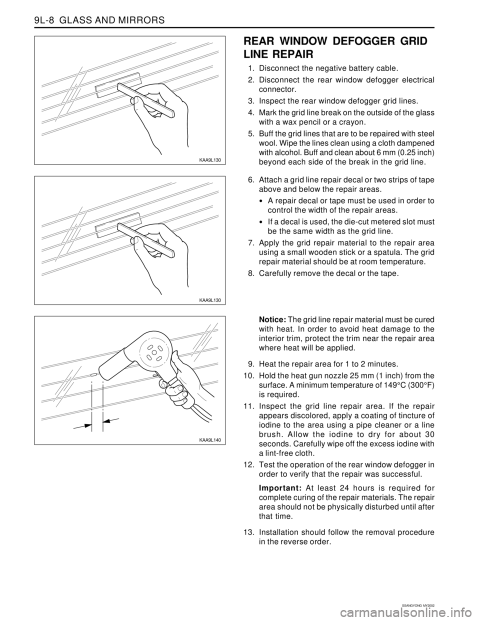
KAA9L140
Notice: The grid line repair material must be cured
with heat. In order to avoid heat damage to the
interior trim, protect the trim near the repair area
where heat will be applied.
9. Heat the repair area for 1 to 2 minutes.
10. Hold the heat gun nozzle 25 mm (1 inch) from the
surface. A minimum temperature of 149°C (300°F)
is required.
11. Inspect the grid line repair area. If the repair
appears discolored, apply a coating of tincture of
iodine to the area using a pipe cleaner or a line
brush. Allow the iodine to dry for about 30
seconds. Carefully wipe off the excess iodine with
a lint-free cloth.
12. Test the operation of the rear window defogger in
order to verify that the repair was successful.
Important: At least 24 hours is required for
complete curing of the repair materials. The repair
area should not be physically disturbed until after
that time.
13. Installation should follow the removal procedure
in the reverse order.
KAA9L130
REAR WINDOW DEFOGGER GRID
LINE REPAIR
1. Disconnect the negative battery cable.
2. Disconnect the rear window defogger electrical
connector.
3. Inspect the rear window defogger grid lines.
4. Mark the grid line break on the outside of the glass
with a wax pencil or a crayon.
5. Buff the grid lines that are to be repaired with steel
wool. Wipe the lines clean using a cloth dampened
with alcohol. Buff and clean about 6 mm (0.25 inch)
beyond each side of the break in the grid line.
KAA9L130
6. Attach a grid line repair decal or two strips of tape
above and below the repair areas.
A repair decal or tape must be used in order to
control the width of the repair areas.
If a decal is used, the die-cut metered slot must
be the same width as the grid line.
7. Apply the grid repair material to the repair area
using a small wooden stick or a spatula. The grid
repair material should be at room temperature.
8. Carefully remove the decal or the tape.