Page 1723 of 2053
SSANGYONG MY2002
9E-6 INSTRUMENTATION, DRIVER INFORMATION
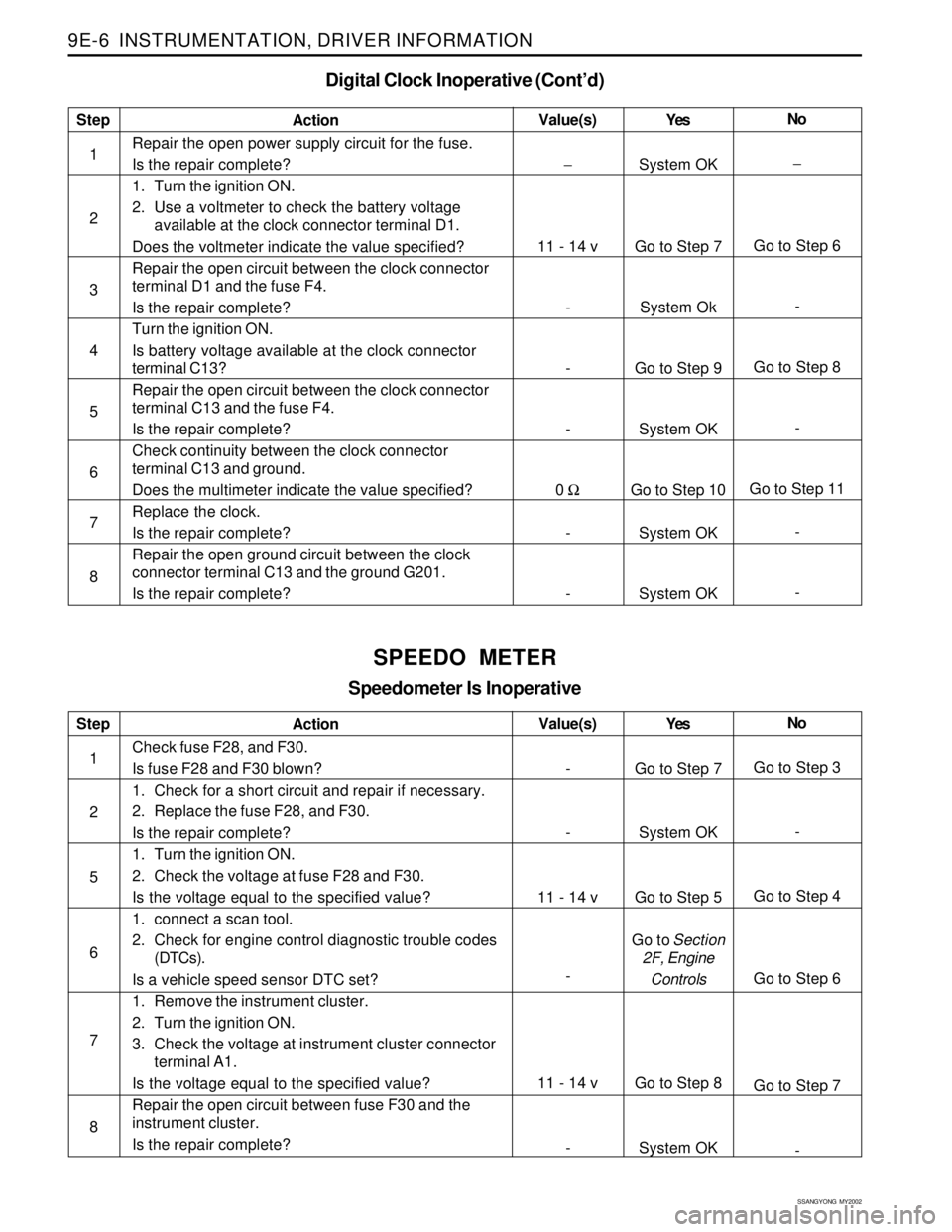
Digital Clock Inoperative (Cont’d)
Step
1
2
3
4
5
6
7
8Action
Repair the open power supply circuit for the fuse.
Is the repair complete?
1. Turn the ignition ON.
2. Use a voltmeter to check the battery voltage
available at the clock connector terminal D1.
Does the voltmeter indicate the value specified?
Repair the open circuit between the clock connector
terminal D1 and the fuse F4.
Is the repair complete?
Turn the ignition ON.
Is battery voltage available at the clock connector
terminal C13?
Repair the open circuit between the clock connector
terminal C13 and the fuse F4.
Is the repair complete?
Check continuity between the clock connector
terminal C13 and ground.
Does the multimeter indicate the value specified?
Replace the clock.
Is the repair complete?
Repair the open ground circuit between the clock
connector terminal C13 and the ground G201.
Is the repair complete?Yes
System OK
Go to Step 7
System Ok
Go to Step 9
System OK
Go to Step 10
System OK
System OKNo
−
Go to Step 6
-
Go to Step 8
-
Go to Step 11
-
- Value(s)
−
11 - 14 v
-
-
-
0 Ω
-
-
SPEEDO METER
Speedometer Is Inoperative
Step
1
2
5
6
7
8Action
Check fuse F28, and F30.
Is fuse F28 and F30 blown?
1. Check for a short circuit and repair if necessary.
2. Replace the fuse F28, and F30.
Is the repair complete?
1. Turn the ignition ON.
2. Check the voltage at fuse F28 and F30.
Is the voltage equal to the specified value?
1. connect a scan tool.
2. Check for engine control diagnostic trouble codes
(DTCs).
Is a vehicle speed sensor DTC set?
1. Remove the instrument cluster.
2. Turn the ignition ON.
3. Check the voltage at instrument cluster connector
terminal A1.
Is the voltage equal to the specified value?
Repair the open circuit between fuse F30 and the
instrument cluster.
Is the repair complete?Yes
Go to Step 7
System OK
Go to Step 5
Go to Section
2F, Engine
Controls
Go to Step 8
System OKNo
Go to Step 3
-
Go to Step 4
Go to Step 6
Go to Step 7
- Value(s)
-
-
11 - 14 v
-
11 - 14 v
-
Page 1726 of 2053
INSTRUMENTATION, DRIVER INFORMATION 9E-9
SSANGYONG MY2002
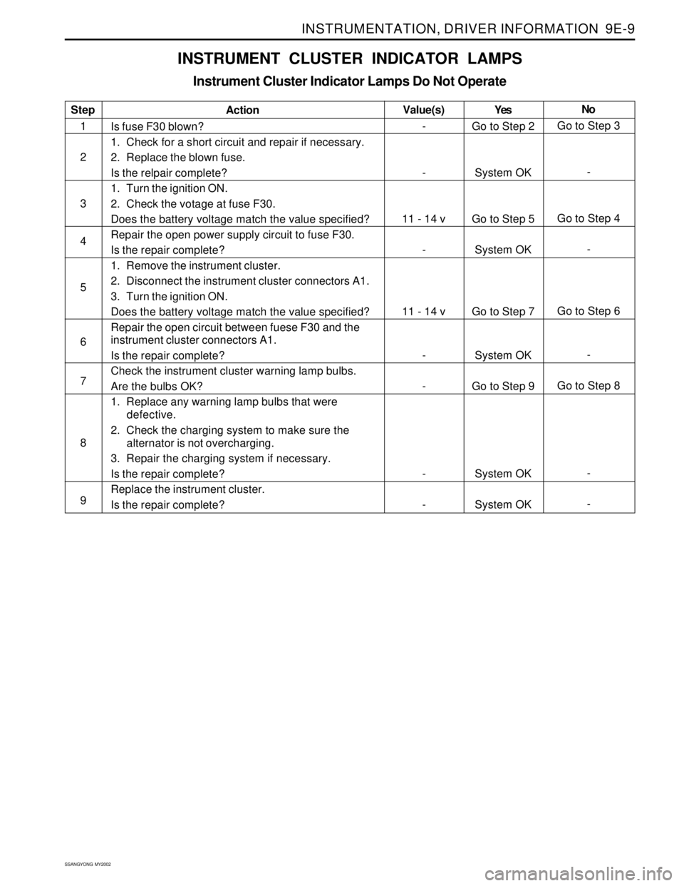
INSTRUMENT CLUSTER INDICATOR LAMPS
Instrument Cluster Indicator Lamps Do Not Operate
Step
1
2
3
4
5
6
7
8
9Action
Is fuse F30 blown?
1. Check for a short circuit and repair if necessary.
2. Replace the blown fuse.
Is the relpair complete?
1. Turn the ignition ON.
2. Check the votage at fuse F30.
Does the battery voltage match the value specified?
Repair the open power supply circuit to fuse F30.
Is the repair complete?
1. Remove the instrument cluster.
2. Disconnect the instrument cluster connectors A1.
3. Turn the ignition ON.
Does the battery voltage match the value specified?
Repair the open circuit between fuese F30 and the
instrument cluster connectors A1.
Is the repair complete?
Check the instrument cluster warning lamp bulbs.
Are the bulbs OK?
1. Replace any warning lamp bulbs that were
defective.
2. Check the charging system to make sure the
alternator is not overcharging.
3. Repair the charging system if necessary.
Is the repair complete?
Replace the instrument cluster.
Is the repair complete?Yes
Go to Step 2
System OK
Go to Step 5
System OK
Go to Step 7
System OK
Go to Step 9
System OK
System OKNo
Go to Step 3
-
Go to Step 4
-
Go to Step 6
-
Go to Step 8
-
- Value(s)
-
-
11 - 14 v
-
11 - 14 v
-
-
-
-
Page 1729 of 2053
SSANGYONG MY2002
9E-12 INSTRUMENTATION, DRIVER INFORMATION
KAA9E090
KAA9E100
KAA9E110
3. Remove the glove box with the screws
4. Installation should follow the removal procedure
in the reverse order.
HOOD LATCH RELEASE HANDLE
Removal and Installation Procedure
1. Remove the hood latch release handle with the
screws.
2. Installation should follow the removal procedure
in the reverse order.
KAA9E080
GLOVE BOX
Removal and Installation Procedure
1. Remove the side facia panel. Refer to “Side Facia
Panel” in this section.
2. Pull and remove the glove box stopper of both.
CHIME MODULE
Removal and Installation Procedure
1. Disconnect the negative battery cable.
2. Remove the center tray. Refer to “Center tray” in
this section.
3. Remove the center facia. Refer to “Center Facia”
in this section.
4. Remove the cup holder. Refer to “Cup Holder” in
this section.
5. Remove the chime module with the screws
6. Installation should follow the removal procedure
in the reverse order.
Page 1731 of 2053
SSANGYONG MY2002
9E-14 INSTRUMENTATION, DRIVER INFORMATION
KAA9E170
KAA9E180
KAA9E190
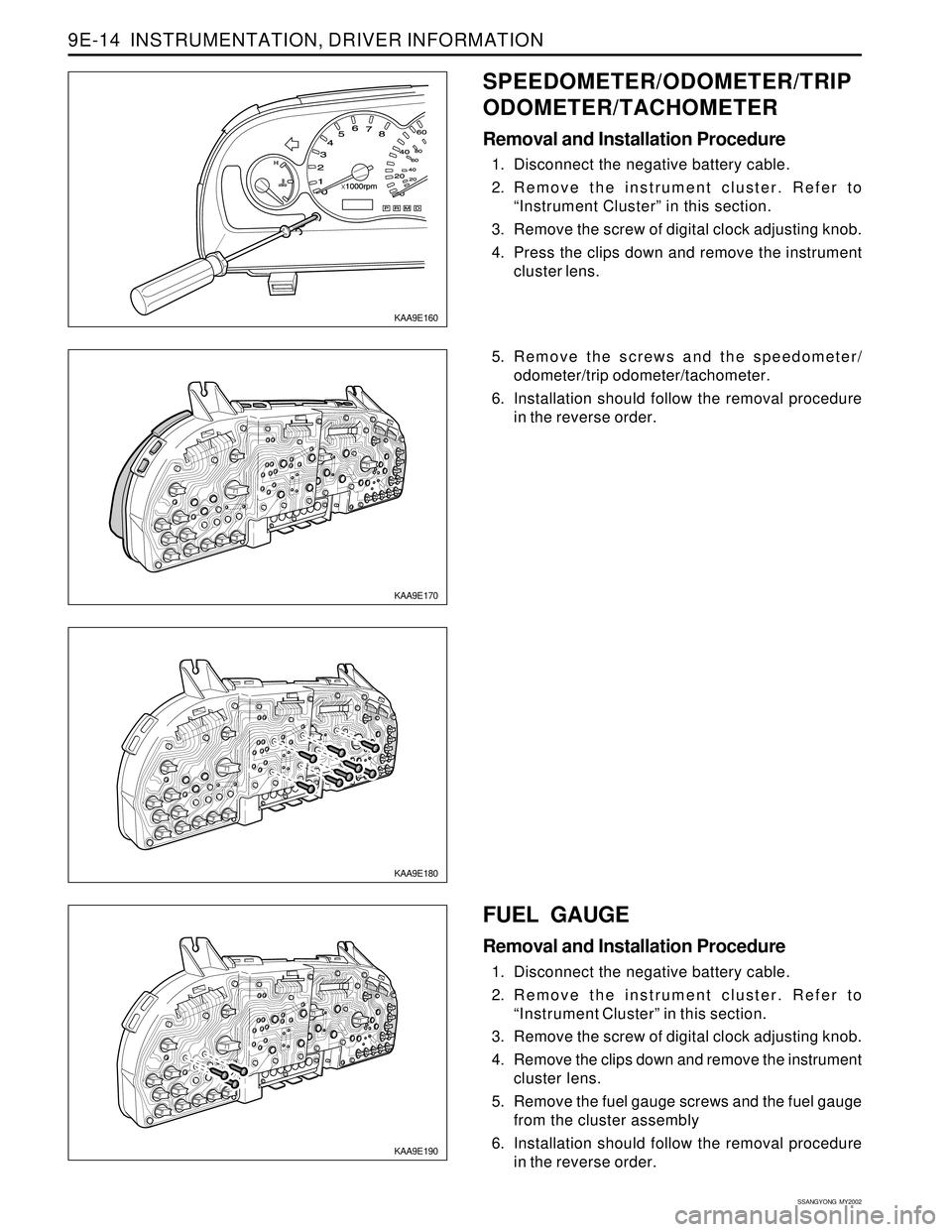
5. Remove the screws and the speedometer/
odometer/trip odometer/tachometer.
6. Installation should follow the removal procedure
in the reverse order.
FUEL GAUGE
Removal and Installation Procedure
1. Disconnect the negative battery cable.
2. Remove the instrument cluster. Refer to
“Instrument Cluster” in this section.
3. Remove the screw of digital clock adjusting knob.
4. Remove the clips down and remove the instrument
cluster lens.
5. Remove the fuel gauge screws and the fuel gauge
from the cluster assembly
6. Installation should follow the removal procedure
in the reverse order.
KAA9E160
SPEEDOMETER/ODOMETER/TRIP
ODOMETER/TACHOMETER
Removal and Installation Procedure
1. Disconnect the negative battery cable.
2. Remove the instrument cluster. Refer to
“Instrument Cluster” in this section.
3. Remove the screw of digital clock adjusting knob.
4. Press the clips down and remove the instrument
cluster lens.
Page 1732 of 2053
INSTRUMENTATION, DRIVER INFORMATION 9E-15
SSANGYONG MY2002
KAA9E210
KAA9E220
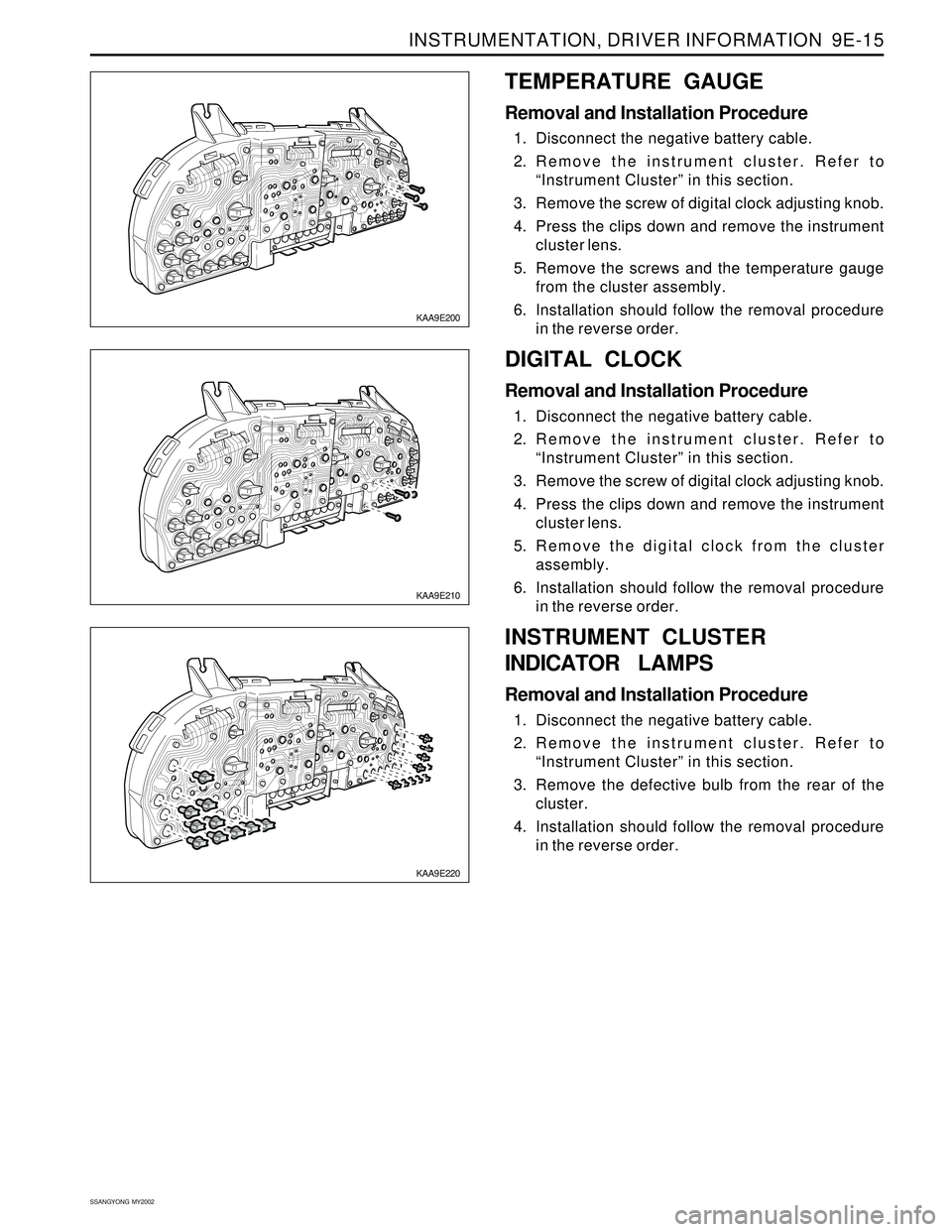
DIGITAL CLOCK
Removal and Installation Procedure
1. Disconnect the negative battery cable.
2. Remove the instrument cluster. Refer to
“Instrument Cluster” in this section.
3. Remove the screw of digital clock adjusting knob.
4. Press the clips down and remove the instrument
cluster lens.
5. Remove the digital clock from the cluster
assembly.
6. Installation should follow the removal procedure
in the reverse order.
KAA9E200
TEMPERATURE GAUGE
Removal and Installation Procedure
1. Disconnect the negative battery cable.
2. Remove the instrument cluster. Refer to
“Instrument Cluster” in this section.
3. Remove the screw of digital clock adjusting knob.
4. Press the clips down and remove the instrument
cluster lens.
5. Remove the screws and the temperature gauge
from the cluster assembly.
6. Installation should follow the removal procedure
in the reverse order.
INSTRUMENT CLUSTER
INDICATOR LAMPS
Removal and Installation Procedure
1. Disconnect the negative battery cable.
2. Remove the instrument cluster. Refer to
“Instrument Cluster” in this section.
3. Remove the defective bulb from the rear of the
cluster.
4. Installation should follow the removal procedure
in the reverse order.
Page 1733 of 2053
SSANGYONG MY2002
9E-16 INSTRUMENTATION, DRIVER INFORMATION
KAA9E250
KAA9E250
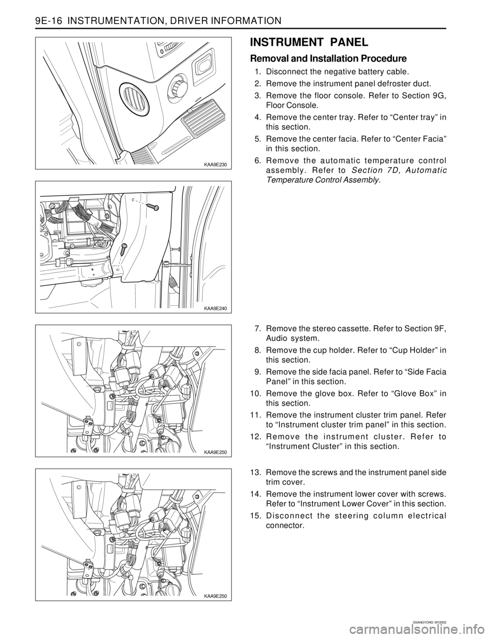
7. Remove the stereo cassette. Refer to Section 9F,
Audio system.
8. Remove the cup holder. Refer to “Cup Holder” in
this section.
9. Remove the side facia panel. Refer to “Side Facia
Panel” in this section.
10. Remove the glove box. Refer to “Glove Box” in
this section.
11. Remove the instrument cluster trim panel. Refer
to “Instrument cluster trim panel” in this section.
12. Remove the instrument cluster. Refer to
“Instrument Cluster” in this section.
13. Remove the screws and the instrument panel side
trim cover.
14. Remove the instrument lower cover with screws.
Refer to “Instrument Lower Cover” in this section.
15. Disconnect the steering column electrical
connector.
KAA9E240
INSTRUMENT PANEL
Removal and Installation Procedure
1. Disconnect the negative battery cable.
2. Remove the instrument panel defroster duct.
3. Remove the floor console. Refer to Section 9G,
Floor Console.
4. Remove the center tray. Refer to “Center tray” in
this section.
5. Remove the center facia. Refer to “Center Facia”
in this section.
6. Remove the automatic temperature control
assembly. Refer to Section 7D, Automatic
Temperature Control Assembly.
KAA9E230
Page 1744 of 2053
Description and Operation.................................. 9F-2
Speakers............................................................ 9F-2
Mast Antenna..................................................... 9F-2
Tape Player and Cassette Care........................... 9F-2
Components Locator ........................................... 9F-3
Audio System..................................................... 9F-3
Repair Instructions............................................... 9F-4
SECTION 9F
AUDIO SYSTEM
CAUTION: Disconnect the negative battery cable before removing or installing any electrical unit or when a
tool or equipment could easily come in contact with exposed electrical terminals. Disconnecting this cable
will help prevent personal injury and damage to the vehicle. The ignition must also be in LOCK unless
otherwise noted.
TABLE OF CONTENTS
On-Vehicle Service Unit Repair............................... 9F-4
Stereo Cassette AM/FM Radio............................ 9F-4
Front Door Speakers........................................... 9F-4
Rear Speakers.................................................... 9F-5
Mast Antenna..................................................... 9F-5
Schematic and Routing Diagram....................... 9F-7
Audio System Circuit .......................................... 9F-7
Page 1747 of 2053
SSANGYONG MY2002
9F-4 AUDIO SYSTEM
KAA9F030
KAA9F040
4. Disconnect the audio system electrical connectors.
5. Installation should follow the removal procedure
in the reverse order.
FRONT DOOR SPEAKERS
Removal and Installation Procedure
1. Disconnect negative battery cable.
2. Remove the front door trim panel. Refer to Section
9G, Interior Trim.
3. Disconnect the electrical connector.
4. Remove the screws and the front door speaker.
5. Installation should follow the removal procedure
in the reverse order.
KAA9F020
ON-VEHICLE SERVICE
UNIT REPAIR
STEREO CASSETTE AM/FM
RADIO
Removal and Installation Procedure
1. Disconnect negative battery cable.
2. Remove the audio system trim plate.
3. Remove the screws and the audio system.
REPAIR INSTRUCTIONS