1997 SSANGYONG KORANDO battery
[x] Cancel search: batteryPage 1575 of 2053
FATC-HAVC 7D-21
SSANGYONG MY2002
KAA7D310
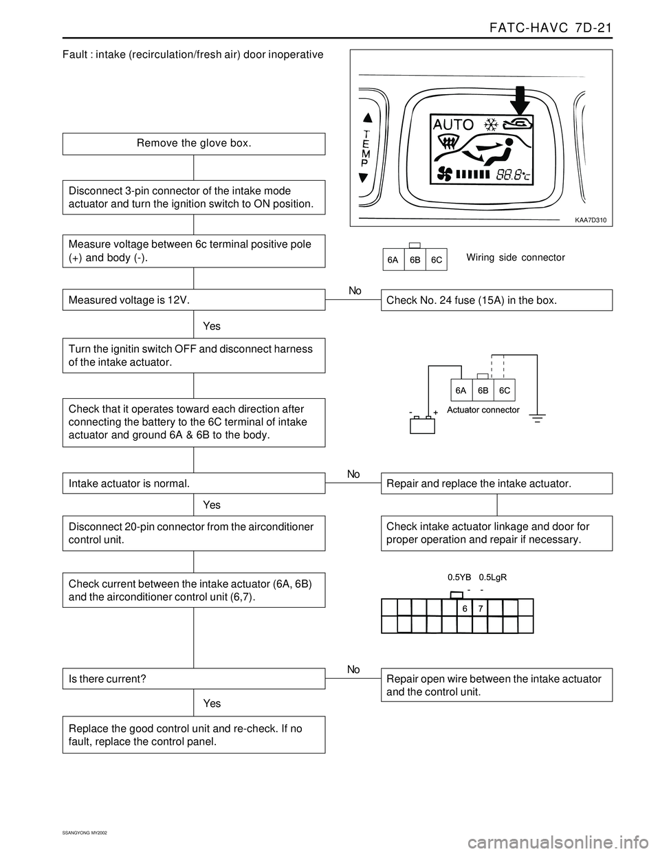
Fault : intake (recirculation/fresh air) door inoperative
Remove the glove box.
Check No. 24 fuse (15A) in the box.
YesNo
Check that it operates toward each direction after
connecting the battery to the 6C terminal of intake
actuator and ground 6A & 6B to the body.
Wiring side connector
Intake actuator is normal.
YesRepair and replace the intake actuator. No
Check intake actuator linkage and door for
proper operation and repair if necessary.Disconnect 20-pin connector from the airconditioner
control unit.
Check current between the intake actuator (6A, 6B)
and the airconditioner control unit (6,7).
Is there current?
YesRepair open wire between the intake actuator
and the control unit. No
Replace the good control unit and re-check. If no
fault, replace the control panel.
Measure voltage between 6c terminal positive pole
(+) and body (-).
Measured voltage is 12V.
Turn the ignitin switch OFF and disconnect harness
of the intake actuator.
Disconnect 3-pin connector of the intake mode
actuator and turn the ignition switch to ON position.
Page 1577 of 2053
SECTION 8A
SEAT BELTS
CAUTION: Disconnect the negative battery cable before removing or installing any electrical unit or when a
tool or equipment could easily come in contact with exposed electrical terminals. Disconnecting this cable
will help prevent personal injury and damage to the vehicle. The ignition must be in B unless otherwise
noted.
TABLE OF CONTENTS
Description and Operation...................................8A-2
Driver Seat Belt Warning......................................8A-2
Three-Point Front Seat Belt With Pretensioner.......8A-2
Three-Point Rear Outboard Seat Belt....................8A-2
Two-Point Lap Rear Center Seat Belt....................8A-2
Operational and Functional Checks......................8A-2
Child Seat Tether Anchor.....................................8A-2
Component Locator.............................................8A-3
Front Seat Belt.....................................................8A-3
Rear Seat Belt.....................................................8A-4Repair Procedures...............................................8A-5
On-Vehicle Service.................................................8A-5
Three-Point Front Seat Belt With Pretensioner.......8A-5
Front Seat Belt Height Adjuster............................8A-6
Three-Point Rear Outboard Seat Belt....................8A-6
Two-Point Lap Rear Center Seat Belt....................8A-7
Child Seat Tether Anchor.....................................8A-7
Specifications.......................................................8A-8
Fastener Tightening Specifications.......................8A-8
Schematic and Routing Diagrams.......................8A-9
Seat Belt & Tension Reducer...............................8A-9
Page 1586 of 2053
SECTION 8B
SUPPLEMENTAL RESTRAINTS SYSTEM
CAUTION: Disconnect the negative battery cable before removing or installing any electrical unit or when a
tool or equipment could easily come in contact with exposed electrical terminals. Disconnecting this cable
will help prevent personal injury and damage to the vehicle. The ignition must also be in LOCK unless
other-wise noted.
TABLE OF CONTENTS
Description and Operation...................................8B-3
Supplemental Restraint System (SRS)..................8B-3
Airbag Modules...................................................8B-3
Front Seat Belt Pretensioners...............................8B-4
Sensing and Diagnostic Module (SDM)................8B-4
Airbag Warning Lamp ..........................................8B-5
Clock Spring........................................................8B-5
Wiring Harness Connectors..................................8B-5
Components Locator............................................8B-6
SRS Component and Wiring Location View...........8B-6
Diagnostic Information and Procedures..............8B-7
Diagnostic Trouble Codes (DTC)..........................8B-7
Scan Tool Diagnostics.........................................8B-7
Use of Special Tools............................................8B-7
Diagnostic Trouble Code Table............................8B-7
SRS Diagnostic System Check..........................8B-10
Sensing and Diagnostic Module (SDM)
Integrity Check...............................................8B-12
Airbag Warning Lamp Stays on with Ignition
Switch ON......................................................8B-14
DTCs - Internal Fault..........................................8B-16
DTCs 01 Driver Deployment Loop Shorted to
Voltage...........................................................8B-18
DTC 02 Passenger Deployment Loop Shorted to
Voltage...........................................................8B-20
DTC 03 Driver Seat Belt Pretensioner Shorted to
Voltage...........................................................8B-22
DTC 04 Passenger Seat Belt Pretensioner
Shorted to Voltage..........................................8B-24
DTC 05 Driver Deployment Loop Shorted to
Ground...........................................................8B-26
DTC 06 Passenger Deployment Loop Shorted to
Ground...........................................................8B-28
DTC 07 Driver Seat Belt Pretensioner Shorted to
Ground...........................................................8B-30DTC 08 Passenger Seat Belt Pretensioner
Shorted to Ground ..........................................8B-32
DTC 17 Driver Deployment Loop
Resistance High.............................................8B-34
DTC 18 Passenger Deployment Loop
Resistance High.............................................8B-38
DTC 19 Driver Seat Belt Pretensioner
Deployment Loop resistance High...................8B-40
DTC 20 Passenger Seat Belt Pretensioner
Deployment Loop Resistance High.................8B-42
DTC 21 Driver Airbag Deployment Loop
Resistance Low..............................................8B-44
DTC 22 Passenger Airbag Deployment Loop
Resistance Low..............................................8B-48
DTC 23 Driver Seat Belt Pretensioner
Deployment Loop resistance Low....................8B-50
DTC 24 Passenger Seat Belt Pretensioner
Deployment Loop Resistance Low..................8B-52
DTC 46 Airbag Warning Lamp Circuit Open or
Short to Ground/Battery..................................8B-54
DTC 47 Battery Voltage is Out of
Specification...................................................8B-56
Repair Instruction...............................................8B-58
On-Vehicle Service...............................................8B-58
Service Precaution.............................................8B-58
Disabling the Supplemental Restraint
System (SRS).................................................8B-58
Enabling the Supplemental Restraint
System (SRS).................................................8B-58
Handling, Installation and Diagnosis..................8B-58
Repairs and Inspections Required After an
Accident ........................................................8B-58
Accident with Deployment - Components
Replacement..................................................8B-58
Accident without Deployment - Component
Inspection......................................................8B-59
Page 1588 of 2053
SUPPLEMENTAL RESTRAINTS SYSTEM 8B-3
SSANGYONG MY2002
SUPPLEMENTAL RESTRAINT
SYSTEM (SRS)
The supplemental restraint system (SRS) is safety de-
vice used in conjunction with the seat belts.
The air bag does not replace the function of the
seatbelt. The driver and the passengers must always
fasten their seat belts adjust them for a proper fit.
The SRS is designed to protect the driver and the front
seat passenger in the event of a significant frontal im-
pact to the vehicle. The airbags deploy if the force is
applied from a direction within about 30 degrees of
the vehicle’s centerline.
The SRS system consists of the following components:
Driver side airbag module.
Passenger airbag module.
Driver’s and passengers front seat belt pretension-
ers.
Sensing and diagnostic module (SDM).
Clock spring.
Wire harness and connectors.
Airbag warning lamp on the instrument cluster.
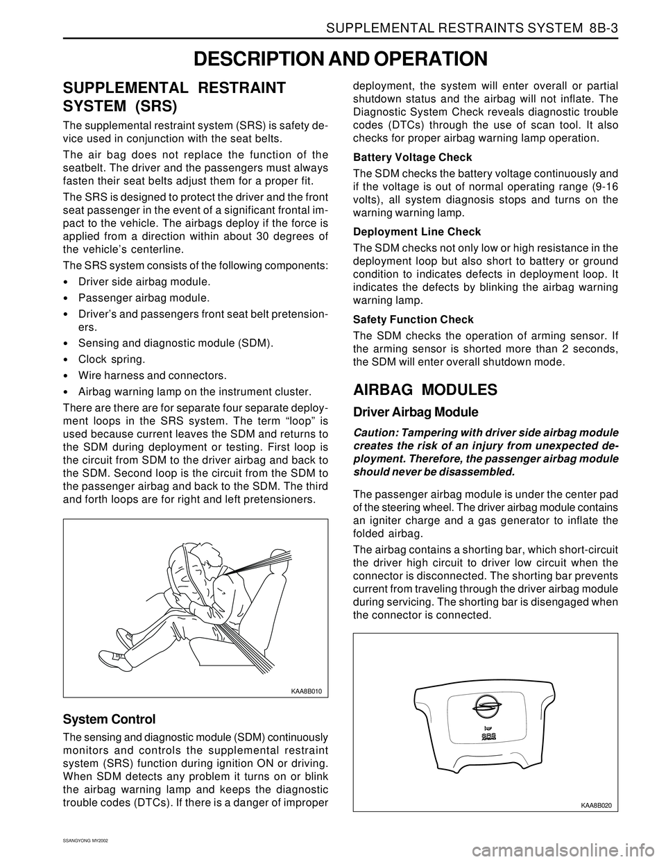
There are there are for separate four separate deploy-
ment loops in the SRS system. The term “loop” is
used because current leaves the SDM and returns to
the SDM during deployment or testing. First loop is
the circuit from SDM to the driver airbag and back to
the SDM. Second loop is the circuit from the SDM to
the passenger airbag and back to the SDM. The third
and forth loops are for right and left pretensioners.
DESCRIPTION AND OPERATION
KAA8B010
deployment, the system will enter overall or partial
shutdown status and the airbag will not inflate. The
Diagnostic System Check reveals diagnostic trouble
codes (DTCs) through the use of scan tool. It also
checks for proper airbag warning lamp operation.
Battery Voltage Check
The SDM checks the battery voltage continuously and
if the voltage is out of normal operating range (9-16
volts), all system diagnosis stops and turns on the
warning warning lamp.
Deployment Line Check
The SDM checks not only low or high resistance in the
deployment loop but also short to battery or ground
condition to indicates defects in deployment loop. It
indicates the defects by blinking the airbag warning
warning lamp.
Safety Function Check
The SDM checks the operation of arming sensor. If
the arming sensor is shorted more than 2 seconds,
the SDM will enter overall shutdown mode.
AIRBAG MODULES
Driver Airbag Module
Caution: Tampering with driver side airbag module
creates the risk of an injury from unexpected de-
ployment. Therefore, the passenger airbag module
should never be disassembled.
The passenger airbag module is under the center pad
of the steering wheel. The driver airbag module contains
an igniter charge and a gas generator to inflate the
folded airbag.
The airbag contains a shorting bar, which short-circuit
the driver high circuit to driver low circuit when the
connector is disconnected. The shorting bar prevents
current from traveling through the driver airbag module
during servicing. The shorting bar is disengaged when
the connector is connected.
System Control
The sensing and diagnostic module (SDM) continuously
monitors and controls the supplemental restraint
system (SRS) function during ignition ON or driving.
When SDM detects any problem it turns on or blink
the airbag warning lamp and keeps the diagnostic
trouble codes (DTCs). If there is a danger of improper
KAA8B020
Page 1590 of 2053
SUPPLEMENTAL RESTRAINTS SYSTEM 8B-5
SSANGYONG MY2002
KAA8B060
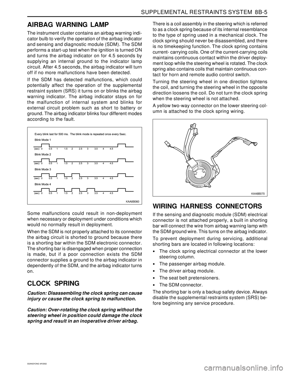
AIRBAG WARNING LAMP
The instrument cluster contains an airbag warning indi-
cator bulb to verify the operation of the airbag indicator
and sensing and diagnostic module (SDM). The SDM
performs a start-up test when the ignition is turned ON
and turns the airbag indicator on for 4.5 seconds by
supplying an internal ground to the indicator lamp
circuit. After 4.5 seconds, the airbag indicator will turn
off if no more malfunctions have been detected.
If the SDM has detected malfunctions, which could
potentially affect the operation of the supplemental
restraint system (SRS) it turns on or blinks the airbag
warning indicator. The airbag indicator stays on for
the malfunction of internal system and blinks for
external circuit problem such as short to battery or
ground. The airbag indicator blinks four different modes
according to the fault.
Some malfunctions could result in non-deployment
when necessary or deployment under conditions which
would no normally result in deployment.
When the SDM is not properly attached to its connector
the airbag circuit is shorted to ground because there
is a shorting bar within the SDM electronic connector.
The shorting bar is disengaged when proper connection
is made, but if a poor connection exists the SDM
connector supplies a ground to the airbag indicator in
dependently of the SDM, and the airbag indicator turns
on.
CLOCK SPRING
Caution: Disassembling the clock spring can cause
injury or cause the clock spring to malfunction.
Caution: Over-rotating the clock spring without the
steering wheel in position could damage the clock
spring and result in an inoperative driver airbag.There is a coil assembly in the steering which is referred
to as a clock spring because of its internal resemblance
to the type of spring used in a mechanical clock. The
clock spring should never be disassembled, and there
is no timekeeping function. The clock spring contains
current- carrying coils. One of the current-carrying coils
maintains continuous contact within the driver deploy-
ment loop while the steering wheel is rotated. The clock
spring also contains coils that maintain continuous con-
tact for horn and remote audio control switch.
Turning the steering wheel in one direction tightens
the coil, and turning the steering wheel in the opposite
direction loosens the coil. Do not turn the clock spring
when the steering wheel is not attached.
A yellow two-way connector on the lower steering col-
umn is attached to the clock spring wiring.
WIRING HARNESS CONNECTORS
If the sensing and diagnostic module (SDM) electrical
connector is not attached properly, a built in shorting
bar will connect the wire from airbag warning lamp with
the SDM ground wire. This turns on the airbag indicator.
To prevent deployment during servicing, additional
shorting bars are located in following locations:
The clock spring electrical connector at the lower
steering column.
The passenger airbag module.
The driver airbag module.
The seat belt pretensioners.
The SDM connector.
The shorting bar is only a backup safety device. Always
disable the supplemental restraints system (SRS) be-
fore beginning any service procedure.
KAA8B070
Page 1593 of 2053
SSANGYONG MY2002
8B-8 SUPPLEMENTAL RESTRAINTS SYSTEM
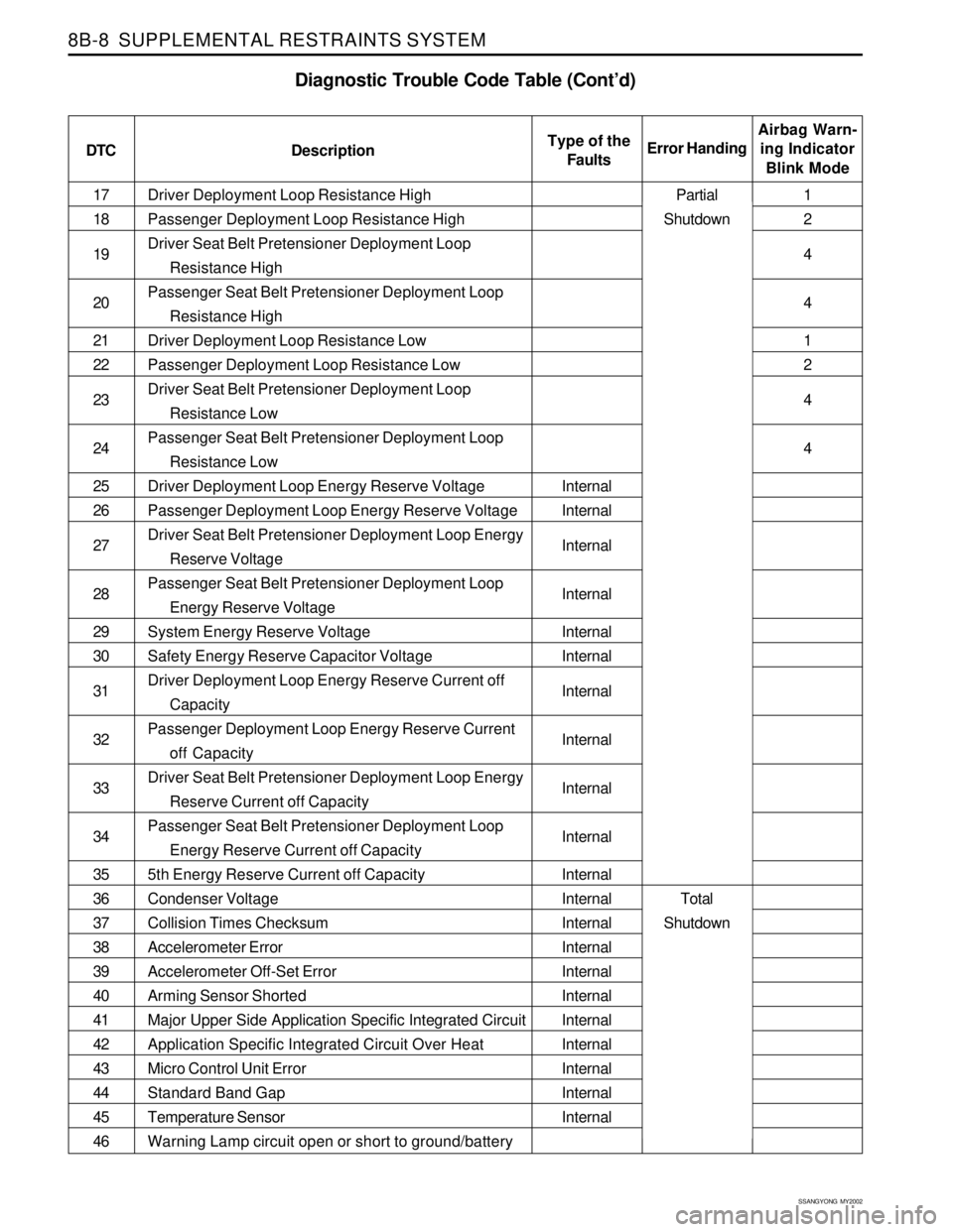
Driver Deployment Loop Resistance High
Passenger Deployment Loop Resistance High
Driver Seat Belt Pretensioner Deployment Loop
Resistance High
Passenger Seat Belt Pretensioner Deployment Loop
Resistance High
Driver Deployment Loop Resistance Low
Passenger Deployment Loop Resistance Low
Driver Seat Belt Pretensioner Deployment Loop
Resistance Low
Passenger Seat Belt Pretensioner Deployment Loop
Resistance Low
Driver Deployment Loop Energy Reserve Voltage
Passenger Deployment Loop Energy Reserve Voltage
Driver Seat Belt Pretensioner Deployment Loop Energy
Reserve Voltage
Passenger Seat Belt Pretensioner Deployment Loop
Energy Reserve Voltage
System Energy Reserve Voltage
Safety Energy Reserve Capacitor Voltage
Driver Deployment Loop Energy Reserve Current off
Capacity
Passenger Deployment Loop Energy Reserve Current
off Capacity
Driver Seat Belt Pretensioner Deployment Loop Energy
Reserve Current off Capacity
Passenger Seat Belt Pretensioner Deployment Loop
Energy Reserve Current off Capacity
5th Energy Reserve Current off Capacity
Condenser Voltage
Collision Times Checksum
Accelerometer Error
Accelerometer Off-Set Error
Arming Sensor Shorted
Major Upper Side Application Specific Integrated Circuit
Application Specific Integrated Circuit Over Heat
Micro Control Unit Error
Standard Band Gap
Temperature Sensor
Warning Lamp circuit open or short to ground/battery 17
18
19
20
21
22
23
24
25
26
27
28
29
30
31
32
33
34
35
36
37
38
39
40
41
42
43
44
45
46
Diagnostic Trouble Code Table (Cont’d)
DTC DescriptionAirbag Warn-
ing Indicator
Blink Mode Error HandingType of the
Faults
Internal
Internal
Internal
Internal
Internal
Internal
Internal
Internal
Internal
Internal
Internal
Internal
Internal
Internal
Internal
Internal
Internal
Internal
Internal
Internal
Internal1
2
4
4
1
2
4
4
Partial
Shutdown
Total
Shutdown
Page 1594 of 2053
SUPPLEMENTAL RESTRAINTS SYSTEM 8B-9
SSANGYONG MY2002
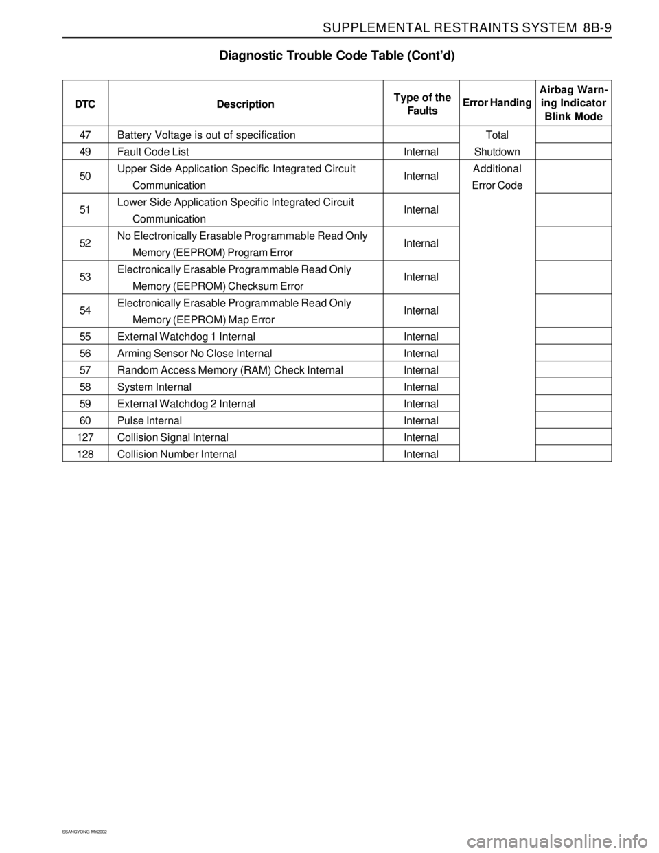
Battery Voltage is out of specification
Fault Code List
Upper Side Application Specific Integrated Circuit
Communication
Lower Side Application Specific Integrated Circuit
Communication
No Electronically Erasable Programmable Read Only
Memory (EEPROM) Program Error
Electronically Erasable Programmable Read Only
Memory (EEPROM) Checksum Error
Electronically Erasable Programmable Read Only
Memory (EEPROM) Map Error
External Watchdog 1 Internal
Arming Sensor No Close Internal
Random Access Memory (RAM) Check Internal
System Internal
External Watchdog 2 Internal
Pulse Internal
Collision Signal Internal
Collision Number Internal 47
49
50
51
52
53
54
55
56
57
58
59
60
127
128
Diagnostic Trouble Code Table (Cont’d)
DTC DescriptionAirbag Warn-
ing Indicator
Blink Mode Error Handing Type of the
Faults
Internal
Internal
Internal
Internal
Internal
Internal
Internal
Internal
Internal
Internal
Internal
Internal
Internal
Internal
Total
Shutdown
Additional
Error Code
Page 1636 of 2053
SSANGYONG MY2002
8B-54 SUPPLEMENTAL RESTRAINTS SYSTEM
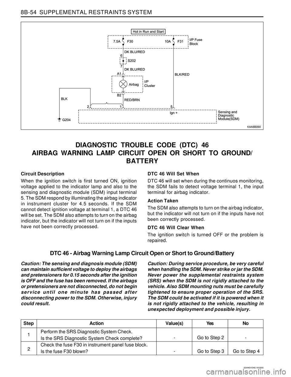
Circuit Description
When the ignition switch is first turned ON, ignition
voltage applied to the indicator lamp and also to the
sensing and diagnostic module (SDM) input terminal
5. The SDM respond by illuminating the airbag indicator
in instrument cluster for 4.5 seconds. If the SDM
cannot detect ignition voltage at terminal 1, a DTC 46
will be set. The SDM also attempts to turn on the airbag
indicator, but the indicator will not turn on if the inputs
have not been correctly processed.
DIAGNOSTIC TROUBLE CODE (DTC) 46
AIRBAG WARNING LAMP CIRCUIT OPEN OR SHORT TO GROUND/
BATTERY
DTC 46 Will Set When
DTC 46 will set when during the continuos monitoring,
the SDM fails to detect voltage terminal 1, the input
terminal for airbag indicator.
Action Taken
The SDM also attempts to turn on the airbag indicator,
but the indicator will not turn on if the inputs have not
been correctly processed.
DTC 46 Will Clear When
The ignition switch is turned OFF or the problem is
repaired.
KAA8B090
DTC 46 - Airbag Warning Lamp Circuit Open or Short to Ground/Battery
Caution: The sensing and diagnosis module (SDM)
can maintain sufficient voltage to deploy the airbags
and pretensioners for 0.15 seconds after the ignition
is OFF and the fuse has been removed. If the airbags
or pretensioners are not disconnected, do not begin
service until one minute has passed after
disconnecting power to the SDM. Otherwise, injury
could result.Caution: During service procedure, be very careful
when handling the SDM. Never strike or jar the SDM.
Never power the supplemental restraints system
(SRS) when the SDM is not rigidly attached to the
vehicle. Also SDM mounting nuts must be carefully
tightened to ensure proper operation of the SRS.
The SDM could be activated if it is powered when it
is not rigidly attached to the vehicle, resulting in
unexpected deployment and possible injury.
Perform the SRS Diagnostic System Check.
Is the SRS Diagnostic System Check complete?
Check the fuse F30 in instrument panel fuse block.
Is the fuse F30 blown?
StepAction Value(s) Yes No
1
- Go to Step 3 Go to Step 4 2
- Go to Step 2 -