1997 SSANGYONG KORANDO battery
[x] Cancel search: batteryPage 1297 of 2053
5A-202 AUTOMATIC TRANSMISSION
SSANGYONG MY2002
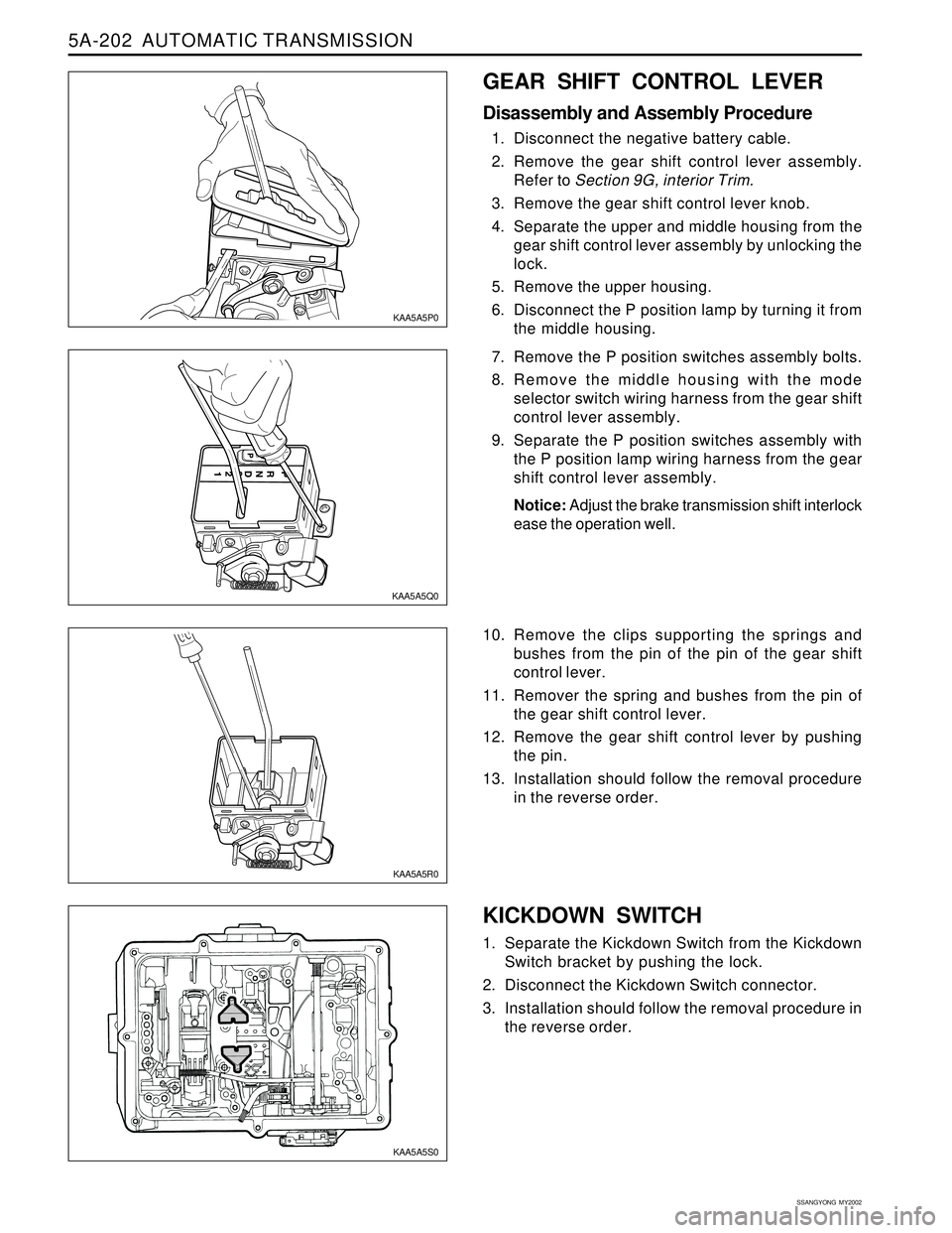
KICKDOWN SWITCH
1. Separate the Kickdown Switch from the Kickdown
Switch bracket by pushing the lock.
2. Disconnect the Kickdown Switch connector.
3. Installation should follow the removal procedure in
the reverse order.
KAA5A5S0
GEAR SHIFT CONTROL LEVER
Disassembly and Assembly Procedure
1. Disconnect the negative battery cable.
2. Remove the gear shift control lever assembly.
Refer to Section 9G, interior Trim.
3. Remove the gear shift control lever knob.
4. Separate the upper and middle housing from the
gear shift control lever assembly by unlocking the
lock.
5. Remove the upper housing.
6. Disconnect the P position lamp by turning it from
the middle housing.
7. Remove the P position switches assembly bolts.
8. Remove the middle housing with the mode
selector switch wiring harness from the gear shift
control lever assembly.
9. Separate the P position switches assembly with
the P position lamp wiring harness from the gear
shift control lever assembly.
Notice: Adjust the brake transmission shift interlock
ease the operation well.
10. Remove the clips supporting the springs and
bushes from the pin of the pin of the gear shift
control lever.
11. Remover the spring and bushes from the pin of
the gear shift control lever.
12. Remove the gear shift control lever by pushing
the pin.
13. Installation should follow the removal procedure
in the reverse order.
KAA5A5P0
KAA5A5Q0
KAA5A5R0
Page 1327 of 2053
MANUAL TRANSMISSION 5B-19
SSANGYONG MY2002
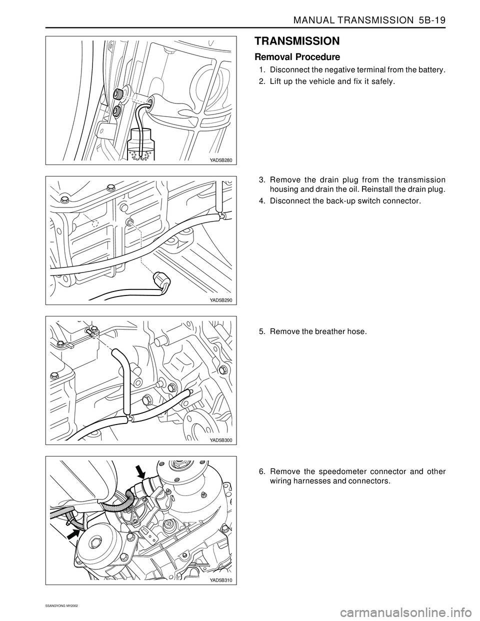
TRANSMISSION
Removal Procedure
1. Disconnect the negative terminal from the battery.
2. Lift up the vehicle and fix it safely.
3. Remove the drain plug from the transmission
housing and drain the oil. Reinstall the drain plug.
4. Disconnect the back-up switch connector.
5. Remove the breather hose.
YAD5B280
YAD5B290
YAD5B300
YAD5B310
6. Remove the speedometer connector and other
wiring harnesses and connectors.
Page 1357 of 2053
Specifications.......................................................5C-2
General Specifications.........................................5C-2
Fastener Tightening Specifications.......................5C-2
Component Locator.............................................5C-3
Clutch Assembly.................................................5C-3
Pedal and Master Cylinder...................................5C-4
Maintenance and Repair.....................................5C-5
On-Vehicle Service.................................................5C-5
Bleeding of Clutch System...................................5C-5
Clutch Disc......................................................... 5C- 6
Master Cylinder.................................................5C-10Clutch Pedal...................................................... 5C-12
Clutch Oil Chamber........................................... 5C-14
Diagnosis............................................................ 5C-15
Clutch Slips....................................................... 5C-15
Poor Disengagement ......................................... 5C-15
Hard to Shift or Will not Shift............................... 5C-15
Clutch Chatters When Starting........................... 5C-15
Difficult Pedal Operation.................................... 5C-16
Clutch Noisy...................................................... 5C-16
Special Tools and Equipment............................ 5C-17
Special Tools Table............................................ 5C-17
SECTION 5C
CLUTCH
CAUTION: Disconnect the negative battery cable before removing or installing any electrical unit or when a
tool or equipment could easily come in contact with exposed electrical terminals. Disconnecting this cable
will help prevent personal injury and damage to the vehicle. The ignition must also be in LOCK unless
otherwise noted.
TABLE OF CONTENTS
Page 1372 of 2053
SECTION 5D1
TRANSFER CASE (TOD)
CAUTION: Disconnect the negative battery cable before removing or installing any electrical unit or when a
tool or equipment could easily come in contact with exposed electrical terminals. Disconnecting this cable
will help prevent personal injury and damage to the vehicle. The ignition must also be in LOCK unless
other-wise noted.
TABLE OF CONTENTS
Description and Operation.................................5D1-2
Torque on Demand (TOD) System
Transfer Case.................................................5D1-2
Transfer Case Control Unit (TCCU).....................5D1-2
TCCU Coding....................................................5D1-2
Pin Description..................................................5D1-3
Components of the TOD Transfer Case System ..5D1-4
Definition of Terminology....................................5D1-4
Operation of the TOD Transfer Case System......5D1-4
Component Locator...........................................5D1-7
Torque on Demand (TOD) Type Transfer Case....5D1-7
Transfer Case Disassembled View.....................5D1-8
TOD Control Unit..............................................5D1-10
Diagnosis..........................................................5D1-11
Self-Diagnostic Tests.......................................5D1-11
Diagnostic Trouble Codes (DTCs)....................5D1-12
Clearing Diagnostic Trouble Codes..................5D1-12
4WD Check Indicator Stays on with Ignition
Switch ON....................................................5D1-14
4WD Low Indicator Stays on with Ignition
Switch ON....................................................5D1-16
No 4WD Check or 4WD Low Indicator with
Ignition Switch ON........................................5D1-18
4WD Low Indicator Blink Steadily.....................5D1-20
TCCU Diagnostic System Check......................5D1-21
DTC 1714 Eeprom Checksum Fault..................5D1-22
DTC 1715 Tp Sensor Loss of Signal.................5D1-24
DTC 1716 Tp Sensor Out of Range...................5D1-26
DTC 1721 Electromagnetic Clutch Open / Short
to Battery.....................................................5D1-28
DTC 1722 Electromagnetic Clutch Short to
Ground.........................................................5D1-32
DTC 1731 Front Speed Sensor Voltage Low......5D1-36
DTC 1732 Front Speed Sensor Voltage High.....5D1-38DTC 1733 Rear Speed Sensor Voltage Low......5D1-40
DTC 1734 Rear Speed Sensor Voltage High.....5D1-42
DTC 1735 Speed Sensor Reference Voltage
Low ..............................................................5D1-44
DTC 1736 Speed Sensor Reference Voltage
High.............................................................5D1-46
DTC 1741 Motor Output Open / Shorted
to Battery.....................................................5D1-48
DTC 1742 Motor Output Shorted to Ground......5D1-52
DTC 1743 Shift System Timeout.......................5D1-55
DTC 1750 General Position Encoder Fault
(Invalid Code)...............................................5D1-56
DTC 1751 Position 1 Shorted to Ground............5D1-58
DTC 1752 Position 2 Shorted to Ground............5D1-60
DTC 1753 Position 3 Shorted to Ground............5D1-62
DTC 1754 Position 4 Shorted to Ground............5D1-64
Repair Instructions............................................5D1-66
On-Vehicle Service.............................................5D1-66
Oil Replacement..............................................5D1-66
Transfer Case Control Unit (TCCU)...................5D1-67
Transfer Case..................................................5D1-67
Shift Motor.......................................................5D1-69
Front and Rear Propeller Shaft Speed Sensor ...5D1-70
Unit Repair........................................................5D1-71
Transfer Case Overhaul...................................5D1-71
Specifications...................................................5D1-79
General Specification.......................................5D1-79
TCCU Electric Characteristics..........................5D1-79
Fastener Tightening Specifications...................5D1-79
Schematic and Routing Diagram....................5D1-80
TOD Transfer Case Control Unit (TCCU)............5D1-80
Special Tools and Equipment..........................5D1-82
Special Tool Table ...........................................5D1-82
Page 1373 of 2053
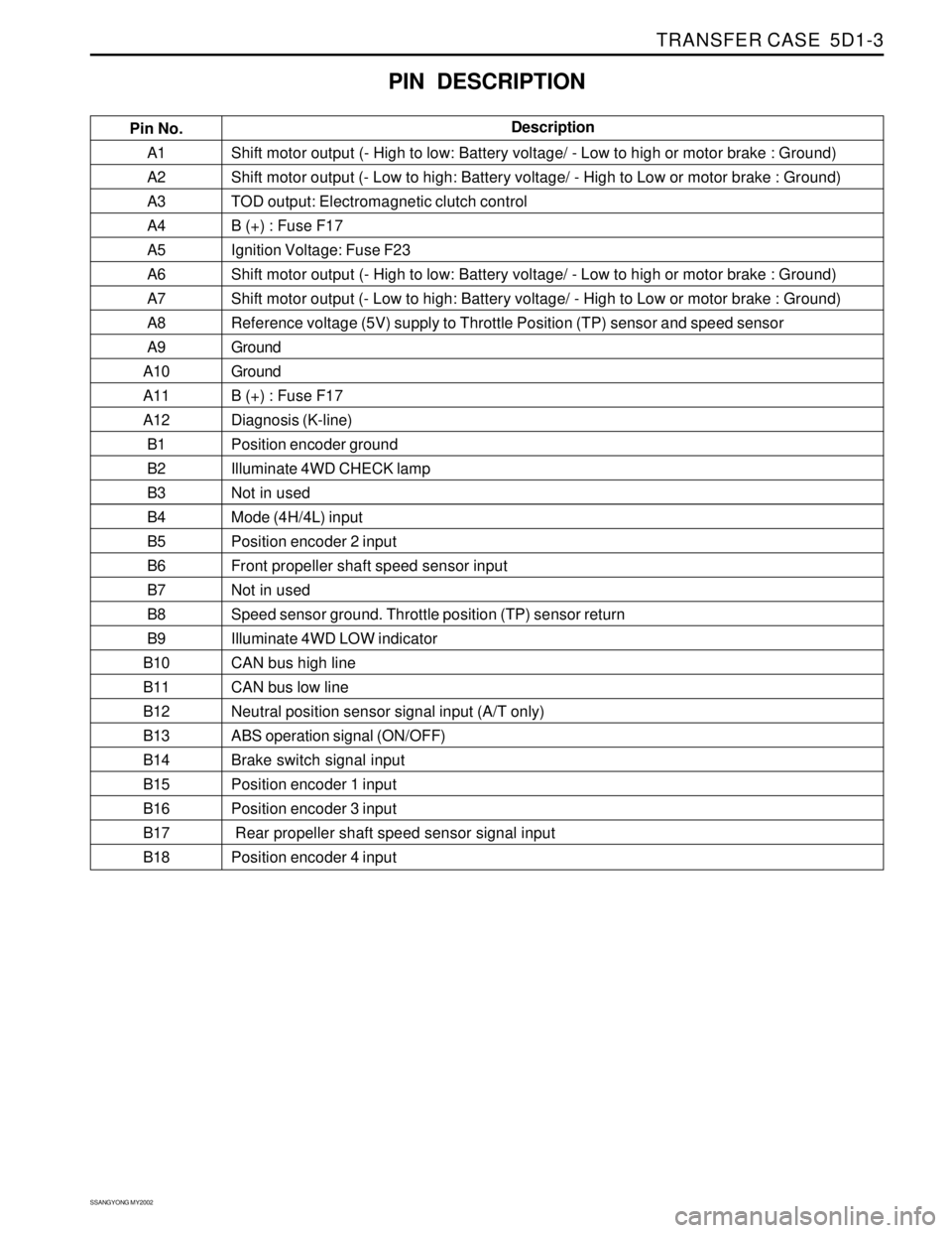
TRANSFER CASE 5D1-3
SSANGYONG MY2002
A1
A2
A3
A4
A5
A6
A7
A8
A9
A10
A11
A12
B1
B2
B3
B4
B5
B6
B7
B8
B9
B10
B11
B12
B13
B14
B15
B16
B17
B18Shift motor output (- High to low: Battery voltage/ - Low to high or motor brake : Ground)
Shift motor output (- Low to high: Battery voltage/ - High to Low or motor brake : Ground)
TOD output: Electromagnetic clutch control
B (+) : Fuse F17
Ignition Voltage: Fuse F23
Shift motor output (- High to low: Battery voltage/ - Low to high or motor brake : Ground)
Shift motor output (- Low to high: Battery voltage/ - High to Low or motor brake : Ground)
Reference voltage (5V) supply to Throttle Position (TP) sensor and speed sensor
Ground
Ground
B (+) : Fuse F17
Diagnosis (K-line)
Position encoder ground
Illuminate 4WD CHECK lamp
Not in used
Mode (4H/4L) input
Position encoder 2 input
Front propeller shaft speed sensor input
Not in used
Speed sensor ground. Throttle position (TP) sensor return
Illuminate 4WD LOW indicator
CAN bus high line
CAN bus low line
Neutral position sensor signal input (A/T only)
ABS operation signal (ON/OFF)
Brake switch signal input
Position encoder 1 input
Position encoder 3 input
Rear propeller shaft speed sensor signal input
Position encoder 4 input
PIN DESCRIPTION
Pin No.Description
Page 1382 of 2053
SSANGYONG MY2002
5D1-12 TRANSFER CASE
Both Speed Sensor Faulty
If both the front and rear speed sensors are faulty con
tinuously for 0.5 seconds the 4WD CHECK lamp is
illuminated. The TCCU then responds as follows:
1. If the system is in high range the TCCU sets the
EMC touch off level based on a vehicle speed of
0 and wheel slip control is suspended.
2. If the system is in low range, the EMC duty cycle
is set to maximum until the system is shifted out
of low range.
3. All electric shift activity is halted until the Ignition
is cycled. If a shift is in progress it will be
completed.
If both speed sensors recover continuously for 0.5 sec-
ond the TCCU will function normally. The 4WD CHECK
lamp is turned off but the fault code will remain in
memory.
Electro-Magnetic Clutch Test
The electromagnetic clutch (EMC) is tested for open
circuit or short circuit to ground. If a fault is detected
continuously for 0.8 second the 4WD CHECK lamp is
turned on and all TODTM activity is halted.
If the EMC recovers continuously for 0.8 second the
TCCU will function normally. The 4WD CHECK lamp is
turned off but the fault code will remain in memory.
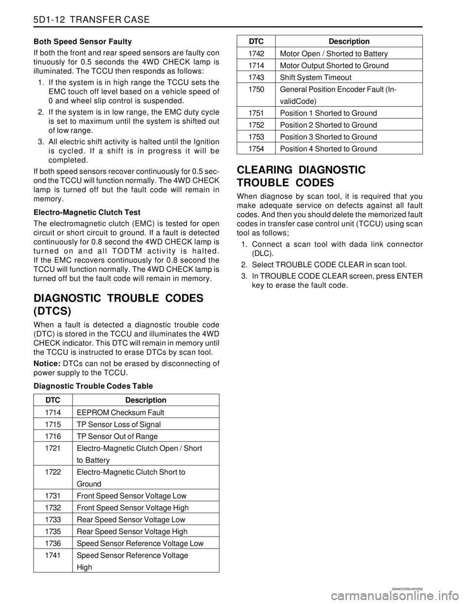
DIAGNOSTIC TROUBLE CODES
(DTCS)
When a fault is detected a diagnostic trouble code
(DTC) is stored in the TCCU and illuminates the 4WD
CHECK indicator. This DTC will remain in memory until
the TCCU is instructed to erase DTCs by scan tool.
Notice: DTCs can not be erased by disconnecting of
power supply to the TCCU.
Diagnostic Trouble Codes Table
CLEARING DIAGNOSTIC
TROUBLE CODES
When diagnose by scan tool, it is required that you
make adequate service on defects against all fault
codes. And then you should delete the memorized fault
codes in transfer case control unit (TCCU) using scan
tool as follows;
1. Connect a scan tool with dada link connector
(DLC).
2. Select TROUBLE CODE CLEAR in scan tool.
3. In TROUBLE CODE CLEAR screen, press ENTER
key to erase the fault code.
Description
EEPROM Checksum Fault
TP Sensor Loss of Signal
TP Sensor Out of Range
Electro-Magnetic Clutch Open / Short
to Battery
Electro-Magnetic Clutch Short to
Ground
Front Speed Sensor Voltage Low
Front Speed Sensor Voltage High
Rear Speed Sensor Voltage Low
Rear Speed Sensor Voltage High
Speed Sensor Reference Voltage Low
Speed Sensor Reference Voltage
High DTC
1714
1715
1716
1721
1722
1731
1732
1733
1735
1736
1741
Description
Motor Open / Shorted to Battery
Motor Output Shorted to Ground
Shift System Timeout
General Position Encoder Fault (In-
validCode)
Position 1 Shorted to Ground
Position 2 Shorted to Ground
Position 3 Shorted to Ground
Position 4 Shorted to Ground DTC
1742
1714
1743
1750
1751
1752
1753
1754
Page 1389 of 2053
TRANSFER CASE 5D1-67
SSANGYONG MY2002
KAA5D260
KAA5D270
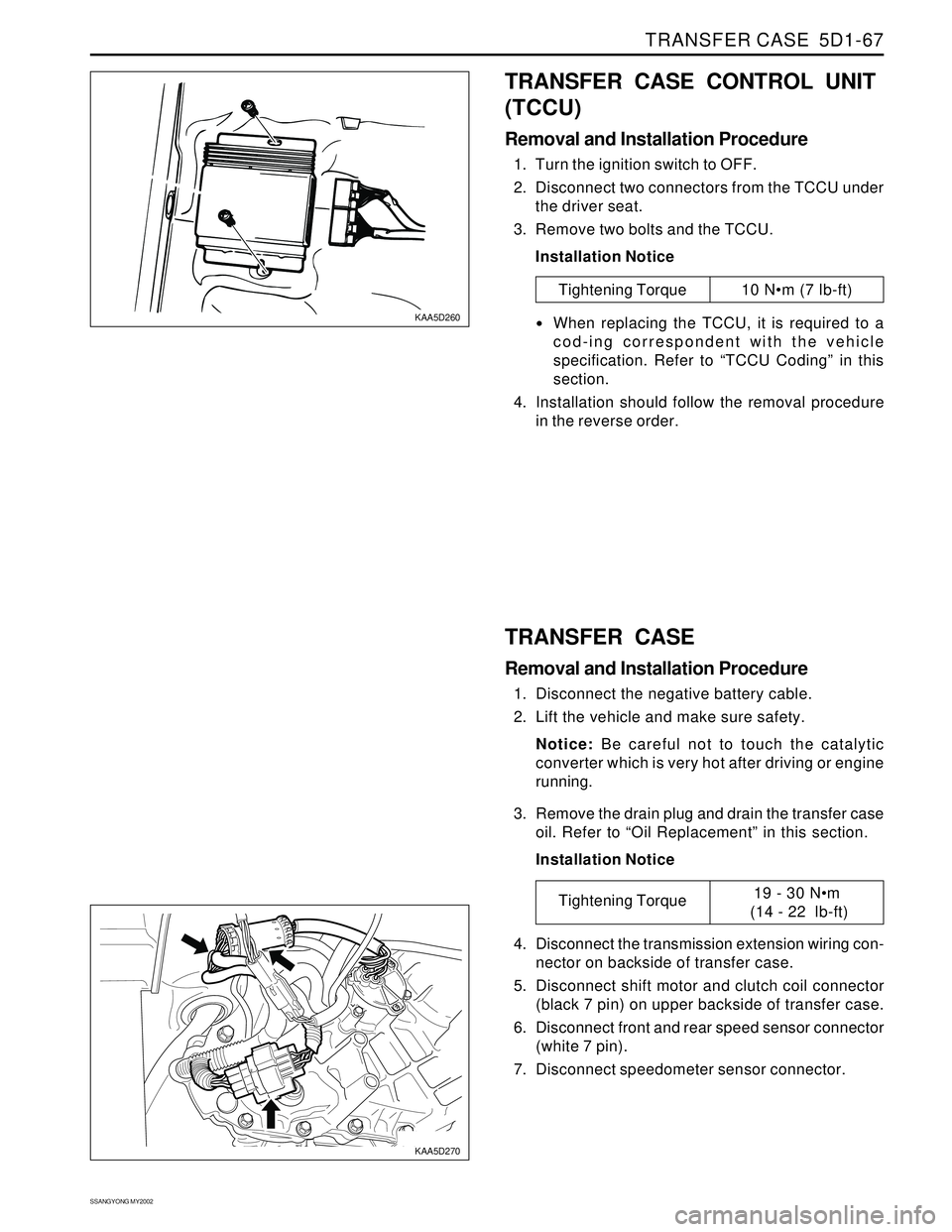
TRANSFER CASE CONTROL UNIT
(TCCU)
Removal and Installation Procedure
1. Turn the ignition switch to OFF.
2. Disconnect two connectors from the TCCU under
the driver seat.
3. Remove two bolts and the TCCU.
Installation Notice
Tightening Torque 10 Nm (7 lb-ft)
When replacing the TCCU, it is required to a
cod-ing correspondent with the vehicle
specification. Refer to “TCCU Coding” in this
section.
4. Installation should follow the removal procedure
in the reverse order.
TRANSFER CASE
Removal and Installation Procedure
1. Disconnect the negative battery cable.
2. Lift the vehicle and make sure safety.
Notice: Be careful not to touch the catalytic
converter which is very hot after driving or engine
running.
3. Remove the drain plug and drain the transfer case
oil. Refer to “Oil Replacement” in this section.
Installation Notice
4. Disconnect the transmission extension wiring con-
nector on backside of transfer case.
5. Disconnect shift motor and clutch coil connector
(black 7 pin) on upper backside of transfer case.
6. Disconnect front and rear speed sensor connector
(white 7 pin).
7. Disconnect speedometer sensor connector.
Tightening Torque19 - 30 Nm
(14 - 22 lb-ft)
Page 1391 of 2053
TRANSFER CASE 5D1-69
SSANGYONG MY2002
KAA5D320
KAA5D330
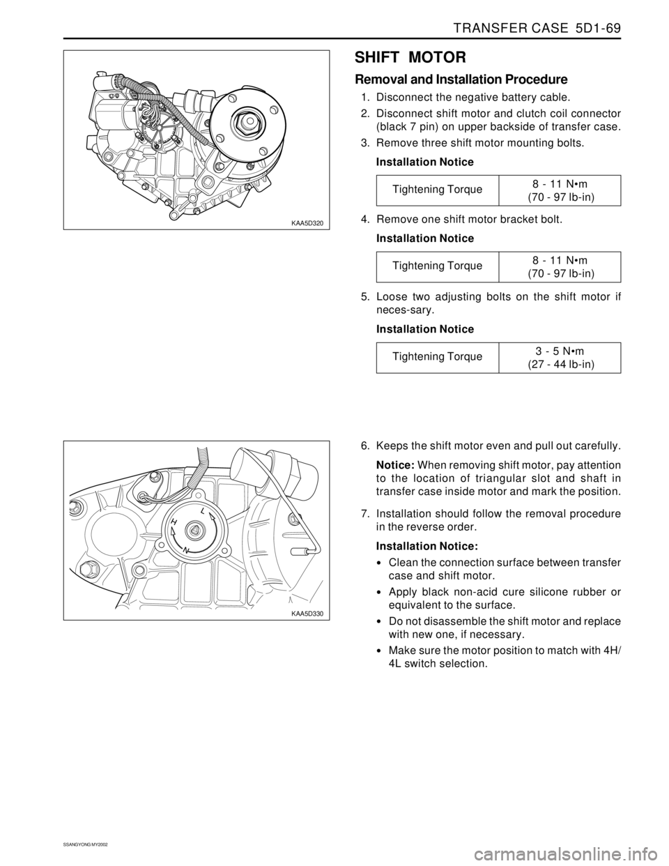
SHIFT MOTOR
Removal and Installation Procedure
1. Disconnect the negative battery cable.
2. Disconnect shift motor and clutch coil connector
(black 7 pin) on upper backside of transfer case.
3. Remove three shift motor mounting bolts.
Installation Notice
6. Keeps the shift motor even and pull out carefully.
Notice: When removing shift motor, pay attention
to the location of triangular slot and shaft in
transfer case inside motor and mark the position.
7. Installation should follow the removal procedure
in the reverse order.
Installation Notice:
Clean the connection surface between transfer
case and shift motor.
Apply black non-acid cure silicone rubber or
equivalent to the surface.
Do not disassemble the shift motor and replace
with new one, if necessary.
Make sure the motor position to match with 4H/
4L switch selection. 4. Remove one shift motor bracket bolt.
Installation Notice
5. Loose two adjusting bolts on the shift motor if
neces-sary.
Installation Notice
Tightening Torque8 - 11 Nm
(70 - 97 lb-in)
Tightening Torque8 - 11 Nm
(70 - 97 lb-in)
Tightening Torque3 - 5 Nm
(27 - 44 lb-in)