1997 SSANGYONG KORANDO battery
[x] Cancel search: batteryPage 1080 of 2053
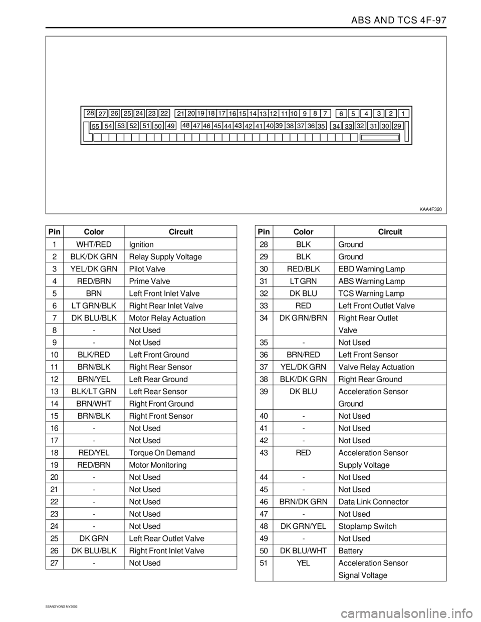
ABS AND TCS 4F-97
SSANGYONG MY2002
KAA4F320
Color
WHT/RED
BLK/DK GRN
YEL/DK GRN
RED/BRN
BRN
LT GRN/BLK
DK BLU/BLK
-
-
BLK/RED
BRN/BLK
BRN/YEL
BLK/LT GRN
BRN/WHT
BRN/BLK
-
-
RED/YEL
RED/BRN
-
-
-
-
-
DK GRN
DK BLU/BLK
- Pin
1
2
3
4
5
6
7
8
9
10
11
12
13
14
15
16
17
18
19
20
21
22
23
24
25
26
27Circuit
Ignition
Relay Supply Voltage
Pilot Valve
Prime Valve
Left Front Inlet Valve
Right Rear Inlet Valve
Motor Relay Actuation
Not Used
Not Used
Left Front Ground
Right Rear Sensor
Left Rear Ground
Left Rear Sensor
Right Front Ground
Right Front Sensor
Not Used
Not Used
Torque On Demand
Motor Monitoring
Not Used
Not Used
Not Used
Not Used
Not Used
Left Rear Outlet Valve
Right Front Inlet Valve
Not UsedColor
BLK
BLK
RED/BLK
LT GRN
DK BLU
RED
DK GRN/BRN
-
BRN/RED
YEL/DK GRN
BLK/DK GRN
DK BLU
-
-
-
RED
-
-
BRN/DK GRN
-
DK GRN/YEL
-
DK BLU/WHT
YEL Pin
28
29
30
31
32
33
34
35
36
37
38
39
40
41
42
43
44
45
46
47
48
49
50
51Circuit
Ground
Ground
EBD Warning Lamp
ABS Warning Lamp
TCS Warning Lamp
Left Front Outlet Valve
Right Rear Outlet
Valve
Not Used
Left Front Sensor
Valve Relay Actuation
Right Rear Ground
Acceleration Sensor
Ground
Not Used
Not Used
Not Used
Acceleration Sensor
Supply Voltage
Not Used
Not Used
Data Link Connector
Not Used
Stoplamp Switch
Not Used
Battery
Acceleration Sensor
Signal Voltage
Page 1082 of 2053
ABS AND TCS 4F-99
SSANGYONG MY2002
REPAIR INSTRUCTIONS
ON-VEHICLE SERVICE
SERVICE PRECAUTIONS
Caution: Brake Fluid may irritate eyes and skin. In
case of contact, take the following actions:
Eye contact - rinse thoroughly with water.
Skin contact - wash with soap and water.
Ingestion - consult a physician immediately.
Caution: To help avoid personal injury due to poor
braking. DO NOT Tap into the vehicle’s brake system
to operate a trailer brake system.
Notice: When fasteners are removed, always reinstall
them at the same location from which they were
removed. If a fastener needs to be replaced, use the
correct part number fastener for is not available, a
fastener of equal size and strength (or stronger) may
be used. Fasteners that are not reused, and those
requiring thread-locking compound will be called out.
The correct torque values must be used when installing
fasteners that require them. If the above procedures
are not followed, parts or system damage could result.
Notice: Use only DOT-3 equivalent hydraulic brake
fluid. The use of DOT-5 (silicone) brake fluid is not
recommended. Reduced brake performance or
durability may result.
Notice: Avoid spilling brake fluid on any the vehicle’s
painted surfaces, wiring, cables or electrical
connectors. Brake fluid will damage paint and electrical
connections. If any fluid is spilled on the vehicle, flush
the area with water to lessen the damage.
Electronic System Service Precautions
Take care to avoid electronic brake control module
(EBCM) circuit overloading. In testing for opens or
shorts, do not ground or apply voltage to any circuit
unless instructed to do so by the diagnostic procedure.
Test circuits only with a high-impedance multi-meter.
Never remove or apply power to any control module
with the ignition switch in the ON position. Always turn
the ignition to the OFF position before removing or
connecting battery cables, fuses or connectors.
General Service Precautions
Disconnect the EBCM connector before performing any
vehicle welding work using an electric arc welder.
Do not attempt to disassemble any component
designated as nonserviceable. The hydraulic modulator
and the EBCM can be separated from each other and
replaced separately but cannot be serviced. They have
no replaceable parts, and there is no replaceable parts,
and there is no access to the components they contain.
Bleeding System
Replacement modulators are shipped already filled
and bled. In normal procedures requiring removal of
the modulator, such as to replace the EBCM, air will
not enter the modulator, and normal bleeding will be
all that is needed.
If air enters the hydraulic modulator, or if an unfilled
modulator is installed, use the brake bleeding program
in the scan tool to bleed the modulator. Manual
bleeding of the hydraulic modulator is not possible.
Page 1083 of 2053
SSANGYONG MY2002
4F-100 ABS AND TCS
1
KAA4F330
KAA4F340
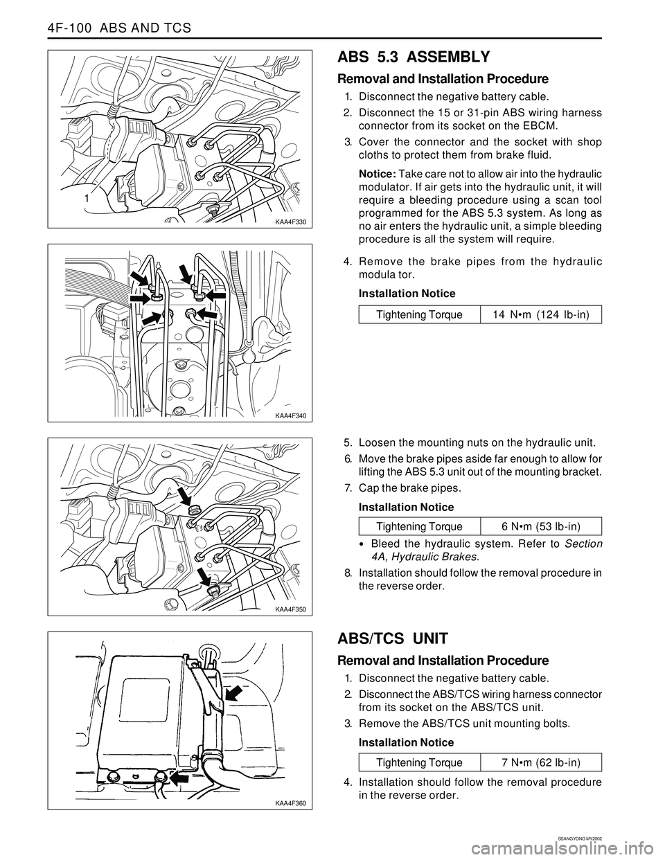
ABS 5.3 ASSEMBLY
Removal and Installation Procedure
1. Disconnect the negative battery cable.
2. Disconnect the 15 or 31-pin ABS wiring harness
connector from its socket on the EBCM.
3. Cover the connector and the socket with shop
cloths to protect them from brake fluid.
Notice: Take care not to allow air into the hydraulic
modulator. If air gets into the hydraulic unit, it will
require a bleeding procedure using a scan tool
programmed for the ABS 5.3 system. As long as
no air enters the hydraulic unit, a simple bleeding
procedure is all the system will require.
4. Remove the brake pipes from the hydraulic
modula tor.
Installation Notice
Tightening Torque 14 Nm (124 lb-in)
5. Loosen the mounting nuts on the hydraulic unit.
6. Move the brake pipes aside far enough to allow for
lifting the ABS 5.3 unit out of the mounting bracket.
7. Cap the brake pipes.
Installation Notice
ABS/TCS UNIT
Removal and Installation Procedure
1. Disconnect the negative battery cable.
2. Disconnect the ABS/TCS wiring harness connector
from its socket on the ABS/TCS unit.
3. Remove the ABS/TCS unit mounting bolts.
Installation Notice
KAA4F350
KAA4F360
Tightening Torque 6 Nm (53 lb-in)
Bleed the hydraulic system. Refer to Section
4A, Hydraulic Brakes.
8. Installation should follow the removal procedure in
the reverse order.
Tightening Torque 7 Nm (62 lb-in)
4. Installation should follow the removal procedure
in the reverse order.
Page 1084 of 2053
ABS AND TCS 4F-101
SSANGYONG MY2002
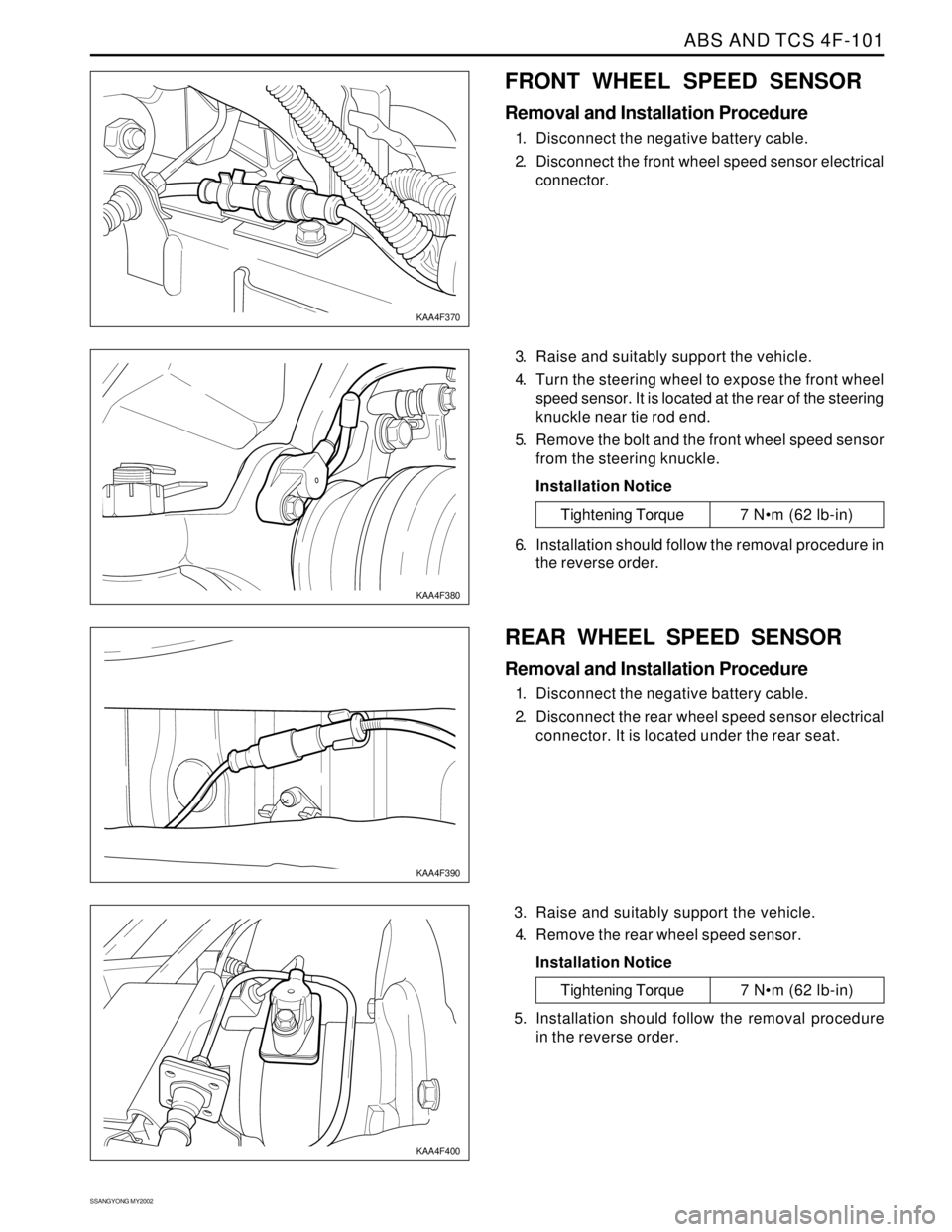
FRONT WHEEL SPEED SENSOR
Removal and Installation Procedure
1. Disconnect the negative battery cable.
2. Disconnect the front wheel speed sensor electrical
connector.
3. Raise and suitably support the vehicle.
4. Turn the steering wheel to expose the front wheel
speed sensor. It is located at the rear of the steering
knuckle near tie rod end.
5. Remove the bolt and the front wheel speed sensor
from the steering knuckle.
Installation Notice
KAA4F370
KAA4F380
Tightening Torque 7 Nm (62 lb-in)
6. Installation should follow the removal procedure in
the reverse order.
REAR WHEEL SPEED SENSOR
Removal and Installation Procedure
1. Disconnect the negative battery cable.
2. Disconnect the rear wheel speed sensor electrical
connector. It is located under the rear seat.
3. Raise and suitably support the vehicle.
4. Remove the rear wheel speed sensor.
Installation Notice
KAA4F390
KAA4F400
Tightening Torque 7 Nm (62 lb-in)
5. Installation should follow the removal procedure
in the reverse order.
Page 1085 of 2053
SSANGYONG MY2002
4F-102 ABS AND TCS
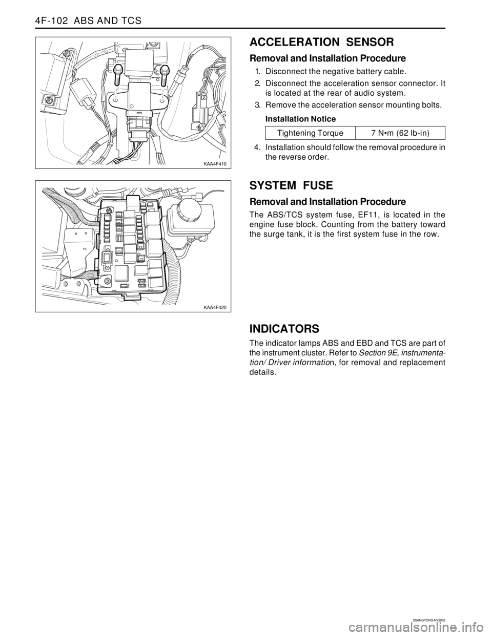
ACCELERATION SENSOR
Removal and Installation Procedure
1. Disconnect the negative battery cable.
2. Disconnect the acceleration sensor connector. It
is located at the rear of audio system.
3. Remove the acceleration sensor mounting bolts.
Installation Notice
SYSTEM FUSE
Removal and Installation Procedure
The ABS/TCS system fuse, EF11, is located in the
engine fuse block. Counting from the battery toward
the surge tank, it is the first system fuse in the row.
KAA4F410
KAA4F420
Tightening Torque 7 Nm (62 lb-in)
4. Installation should follow the removal procedure in
the reverse order.
INDICATORS
The indicator lamps ABS and EBD and TCS are part of
the instrument cluster. Refer to Section 9E, instrumenta-
tion/ Driver information, for removal and replacement
details.
Page 1095 of 2053
SECTION 5A
AUTOMATIC TRANSMISSION
CAUTION: Disconnect the negative battery cable before removing or installing any electrical unit or when a
tool or equipment could easily come in contact with exposed electrical terminals. Disconnecting this cable
will help prevent personal injury and damage to the vehicle. The ignition must also be in LOCK unless
otherwise noted.
TABLE OF CONTENTS
Description and Operation . . . . . . . . . . . . . . . . . 5A-2
BTRA M74 4WD Automatic Transmission . . . . . . 5A-2
Operators Interfaces . . . . . . . . . . . . . . . . . . . . . 5A-2
Control Systems . . . . . . . . . . . . . . . . . . . . . . . . 5A-3
Electronic Control System . . . . . . . . . . . . . . . . . 5A-3
Hydraulic Control System . . . . . . . . . . . . . . . . . . 5A-9
Hydraulic Control Circuit . . . . . . . . . . . . . . . . . . 5A-10
Power Train System . . . . . . . . . . . . . . . . . . . . . 5A-14
Power Flows . . . . . . . . . . . . . . . . . . . . . . . . . . 5A-18
Park and Neutral . . . . . . . . . . . . . . . . . . . . . . . 5A-20
Reverse . . . . . . . . . . . . . . . . . . . . . . . . . . . . . . 5A-22
Manual 1 . . . . . . . . . . . . . . . . . . . . . . . . . . . . . 5A-24
Drive 1 . . . . . . . . . . . . . . . . . . . . . . . . . . . . . . 5A-26
Drive 2 and Manual 2 . . . . . . . . . . . . . . . . . . . . 5A-28
Drive 3 and Manual 3 . . . . . . . . . . . . . . . . . . . . 5A-30
Drive 3 Lock Up and Manual 3 Lock Up . . . . . . 5A-32
Drive 4 (Overdrive) . . . . . . . . . . . . . . . . . . . . . 5A-34
Drive 4 Lock Up . . . . . . . . . . . . . . . . . . . . . . . . 5A-36
Diagnostic Information and Procedures . . . . . 5A-38
Diagnosis . . . . . . . . . . . . . . . . . . . . . . . . . . . . . 5A-38
Basic Knowledge Required . . . . . . . . . . . . . . . 5A-38
Functional Check Procedure . . . . . . . . . . . . . . . 5A-38
Transmission Fluid Level Service Procedure . . . 5A-38
Fluid Leak Diagnosis and Repair . . . . . . . . . . . 5A-39
Electrical / Garage Shift Test . . . . . . . . . . . . . . 5A-40
Road Test Procedure . . . . . . . . . . . . . . . . . . . . 5A-40
Electronic Adjustments . . . . . . . . . . . . . . . . . . 5A-40
Symptom Diagnosis . . . . . . . . . . . . . . . . . . . . . 5A-41
Drive Faults . . . . . . . . . . . . . . . . . . . . . . . . . . . 5A-41
Faulty Shift Pattern . . . . . . . . . . . . . . . . . . . . . . 5A-42Shift Quality Faults . . . . . . . . . . . . . . . . . . . . . . 5A-44
After Teardown Faults . . . . . . . . . . . . . . . . . . . 5A-46
Trouble Code Diagnosis - Gasoline Vehicle . . 5A-48
TCM Diagnostic System Overview . . . . . . . . . . 5A-48
Clearing Trouble Codes . . . . . . . . . . . . . . . . . . 5A-48
Diagnostic Trouble Codes . . . . . . . . . . . . . . . . 5A-48
Trouble Code Diagnosis - Diesel Vehicle . . . . . 5A-50
TCM Diagnostic System Overview . . . . . . . . . . 5A-50
Clearing Trouble Codes . . . . . . . . . . . . . . . . . . 5A-50
Diagnostic Trouble Codes . . . . . . . . . . . . . . . . 5A-50
Repair Instructions . . . . . . . . . . . . . . . . . . . . . . 5A-157
On-Vehicle Service . . . . . . . . . . . . . . . . . . . . . . . 5A-157
Transmission . . . . . . . . . . . . . . . . . . . . . . . . . . 5A-157
Unit Repair . . . . . . . . . . . . . . . . . . . . . . . . . . . . 5A-160
Rebuild Warnings . . . . . . . . . . . . . . . . . . . . . . 5A-160
Disassembly Procedure . . . . . . . . . . . . . . . . . . 5A-161
Assembly Procedure . . . . . . . . . . . . . . . . . . . . 5A-171
Front and Rear Band Adjustment . . . . . . . . . . . 5A-199
Gear Shift Control Lever . . . . . . . . . . . . . . . . . . 5A-202
Kickdown Switch . . . . . . . . . . . . . . . . . . . . . . . 5A-202
Specifications . . . . . . . . . . . . . . . . . . . . . . . . . . 5A-203
General Specification . . . . . . . . . . . . . . . . . . . . 5A-203
Fastener Tightening Specifications . . . . . . . . . . 5A-205
Schematic and Routing Diagrams . . . . . . . . . . 5A-206
TCM Wiring Diagrams (Gasoline Engine) . . . . . 5A-206
TCM Wiring Diagrams (Diesel Engine) . . . . . . . 5A-208
Connector End View . . . . . . . . . . . . . . . . . . . . . 5A-210
Special Tools and Equipment . . . . . . . . . . . . . 5A-211
Special Tools Table . . . . . . . . . . . . . . . . . . . . . 5A-211
Page 1100 of 2053
5A-6 AUTOMATIC TRANSMISSION
SSANGYONG MY2002
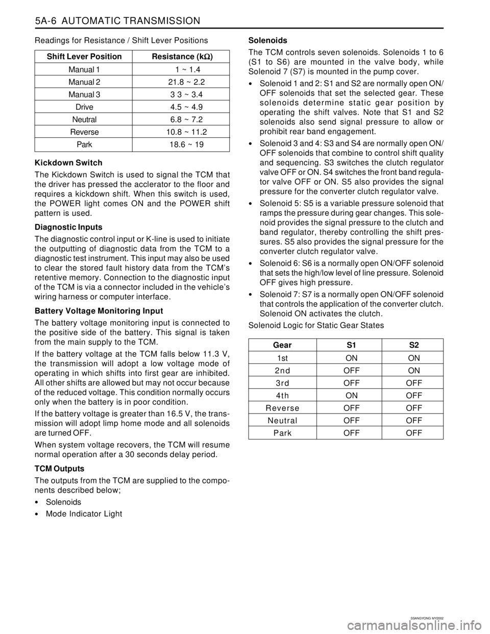
Solenoids
The TCM controls seven solenoids. Solenoids 1 to 6
(S1 to S6) are mounted in the valve body, while
Solenoid 7 (S7) is mounted in the pump cover.
Solenoid 1 and 2: S1 and S2 are normally open ON/
OFF solenoids that set the selected gear. These
solenoids determine static gear position by
operating the shift valves. Note that S1 and S2
solenoids also send signal pressure to allow or
prohibit rear band engagement.
Solenoid 3 and 4: S3 and S4 are normally open ON/
OFF solenoids that combine to control shift quality
and sequencing. S3 switches the clutch regulator
valve OFF or ON. S4 switches the front band regula-
tor valve OFF or ON. S5 also provides the signal
pressure for the converter clutch regulator valve.
Solenoid 5: S5 is a variable pressure solenoid that
ramps the pressure during gear changes. This sole-
noid provides the signal pressure to the clutch and
band regulator, thereby controlling the shift pres-
sures. S5 also provides the signal pressure for the
converter clutch regulator valve.
Solenoid 6: S6 is a normally open ON/OFF solenoid
that sets the high/low level of line pressure. Solenoid
OFF gives high pressure.
Solenoid 7: S7 is a normally open ON/OFF solenoid
that controls the application of the converter clutch.
Solenoid ON activates the clutch.
Solenoid Logic for Static Gear States
Gear S1 S2
1st ON ON
2nd OFF ON
3 r d OFF OFF
4th ON OFF
Reverse OFF OFF
Neutral OFF OFF
Park OFF OFF
Shift Lever Position Resistance (k
Ω ΩΩ Ω
Ω)
Manual 1 1 ~ 1.4
Manual 221.8 ~ 2.2
Manual 3 3 3 ~ 3.4
Drive4.5 ~ 4.9
Neutral6.8 ~ 7.2
Reverse10.8 ~ 11.2
Park18.6 ~ 19
Kickdown Switch
The Kickdown Switch is used to signal the TCM that
the driver has pressed the acclerator to the floor and
requires a kickdown shift. When this switch is used,
the POWER light comes ON and the POWER shift
pattern is used.
Diagnostic Inputs
The diagnostic control input or K-line is used to initiate
the outputting of diagnostic data from the TCM to a
diagnostic test instrument. This input may also be used
to clear the stored fault history data from the TCM’s
retentive memory. Connection to the diagnostic input
of the TCM is via a connector included in the vehicle’s
wiring harness or computer interface.
Battery Voltage Monitoring Input
The battery voltage monitoring input is connected to
the positive side of the battery. This signal is taken
from the main supply to the TCM.
If the battery voltage at the TCM falls below 11.3 V,
the transmission will adopt a low voltage mode of
operating in which shifts into first gear are inhibited.
All other shifts are allowed but may not occur because
of the reduced voltage. This condition normally occurs
only when the battery is in poor condition.
If the battery voltage is greater than 16.5 V, the trans-
mission will adopt limp home mode and all solenoids
are turned OFF.
When system voltage recovers, the TCM will resume
normal operation after a 30 seconds delay period.
TCM Outputs
The outputs from the TCM are supplied to the compo-
nents described below;
Solenoids
Mode Indicator Light Readings for Resistance / Shift Lever Positions
Page 1132 of 2053
5A-38 AUTOMATIC TRANSMISSION
SSANGYONG MY2002
DIAGNOSIS
BASIC KNOWLEDGE REQUIRED
You must be familliar with some basic electronics to
use this section of the Service Manual. They will help
you to follow diagnostic procedures.
Notice: Lack of the basic knowledge of this transmis-
sion when performing diagnostic procedures could re-
sult in incorrect diagnostic performance or damage to
transmission components. Do not, under any circum-
stances, attempt to diagnose a transmission problem
without this basic knowledge.
Notice: If a wire is probed with a sharp instrument
and not properly sealed afterward, the wire will corrode
and an open circuit will result.
Diagnostic test probes are now available that allow
you to probe individual wires without leaving the wire
open to the environment. These probe devices are
inexpensive and easy to install, and they permanently
seal the wire from corrosion.
Special Tools
You should be able to use a Digital Volt Meter (DVM),
a circuit tester, jumper wires or leads and a line
pressure gauge set. The functional check procedure
is designed to verify the correct operation of electronic
components in the transmission. This will eliminate the
unnecessary removal of transmission components.
FUNCTIONAL CHECK
PROCEDURE
Begin with the Functional Check Procedure which pro-
vides a general outline of how to diagnose automatic
transmission. The following functional check procedure
will indicate the proper path of diagnosing the transmis-
sion by describing the basic checks and then referenc-
ing the locations of the specific checks.
Check the fluid level according to the Fluid Level
Service Procedure.
Check the transmission fluid leak.
Check if the transmission fluid is not burnt by smell.
Notice: The specific fluid used in this transmission
turns brown during normal operation. Brown fluid
does not indicate a transmission fault.
Ensure that the transmission is not in Limp Home
Mode (LHM).
Check the battery terminals and the earth connec-
tions for corrosion or looseness.
Check that the cooler flow is not restricted.
Check all electrical plug connections for tightness.
Use on-board diagnostic tool or a scan tool to see
if any transmission trouble codes have been set.
DIAGNOSTIC INFORMATION AND PROCEDURES
Refer to the appropriate “Diagnostic Trouble Code
(DTC)” information and repair the vehicle as
directed. After repairing the vehicle, perform the
road test and verify that the code has not set again.
Perform the Electrical/Garage Shift Tests.
Perform the Road Test Procedure in this section.
Inspect the oil and check for metal or other contami-
nants in the oil pan.
TRANSMISSION FLUID LEVEL
SERVICE PROCEDURE
This procedure is to be used when checking a concern
with the fluid level in a vehicle. A low fluid level will
result in slipping and loss of drive/ reverse or delay on
engagement of drive/ reverse when the vehicle is cold.
The vehicle is first checked for transmission diagnostic
messages on the scan tool. If the oil level is low, it is
possible to register a vehicle speed signal fault.
The vehicle is to be test driven to determine if there is
an abnormal delay when selecting drive or reverse, or
loss of drive. One symptom of low fluid level is a
momentary loss of drive when driving the vehicle around
a corner. Also when the transmission fluid level is low,
a loss of drive may occur when the transmission fluid
temperature is low.
If there is no loss of drive when the vehicle is driven
warm and a vehicle speed signal fault is registered,
then fluid should be added to the transmission.
When adding or changing transmission fluid use only
Castrol TQ 95 automatic transmission fluid. The use of
incorrect fluid will cause the performance and durability
of the transmission to be severely degraded.
Fluid Level Diagnosis procedure
1. If the vehicle is at operating temperature allow the
vehicle to cool down for two hours, but no greater
than four hours. Or if the vehicle is at cool status,
start the engine and allow the engine to idle for
approximately 5 minutes or, if possible, drive the
vehicle for a few kilometers. This will allow the
transmission to be within the correct temperature
range. Transmission fluid level should be checked
at temperature 50 - 60 °C (82 - 140 °F).
Caution: Removal of the fluid filler plug when
the transmission fluid is hot may cause injury if
fluid drains from the filler hole.
2. With the brake pedal pressed, move the gear shift
control lever through the gear ranges, pausing a
few seconds in each range. Return the gear shift
control lever to P (Park). Turn the engine OFF.
3. Park the vehicle on a hoist, inspection pit or similar
raised level surface. The vehicle must be control
level to obtain a correct fluid level measurement.