Page 1049 of 2053
SSANGYONG MY2002
4F-66 ABS AND TCS
DIAGNOSTIC TROUBLE CODE (DTC) 17/18
LEFT REAR INLET AND OUTLET VALVE SOLENOID FAULT
KAA4F200
Circuit Description
The solenoid valve coil circuits are supplied with power
from the battery when the valve relay is energized.
Switched ground is provided by the electronic brake
control module (EBCM) to each coil.
Diagnosis
This procedure checks whether the left rear inlet and
outlet valves are functioning.
Cause(s)
A valve has failed.
A solenoid coil is open or shorted.Fail Action
ABS is disabled, and the ABS warning lamp is turned
ON for the remainder of the ignition cycle. If the failure
is intermittent, the EBCM will enable the system at the
next ignition cycle and set a history DTC.
Test Description
The number(s) below refer to step(s) on the diagnostic
table.
1. This begins the test of the inlet valve.
3. his tests the outlet valve.
Page 1051 of 2053
SSANGYONG MY2002
4F-68 ABS AND TCS
DIAGNOSTIC TROUBLE COED (DTC) 19/20 - RIGHT REAR INLET AND
OUTLET VALVE SOLENOID FAULT
Circuit Description
The solenoid valve coil circuits are supplied with power
from the battery when the valve relay is energized.
Switched ground is provided by the electronic brake
control module (EBCM) to each coil.
Diagnosis
This procedure checks whether the right rear inlet and
outlet valves are functioning.
Cause(s)
A valve has failed.
A solenoid coil is open or shorted.Action Taken When the DTC Sets
ABS is disabled, and the ABS warning lamp is turned
ON for the remainder of the ignition cycle. If the failure
is intermittent, the EBCM will enable the system at the
next ignition cycle and set a history DTC.
Test Description
The number(s) below refer to step(s) on the diagnostic
table.
1. This begins the test of the inlet valve
3. This tests the outlet valve.
KAA4F200
Page 1053 of 2053
SSANGYONG MY2002
4F-70 ABS AND TCS
DIAGNOSTIC TROUBLE CODE (DTC) 21/22
LEFT REAR PRIME LINE AND TRACTION CONTROL
SYSTEM (TCS) PILOT VALVE FAULT
KAA4F200
Circuit Description
The solenoid valve coil circuits are supplied with power
from the battery when the valve relay is energized.
Switched ground is provided by the electronic brake
control module (EBCM) to each coil.
Diagnosis
This procedure checks whether the left rear TCS valves
are functioning.Cause(s)
A solenoid coil is open or shorted.
Fail Action
Antilock brake system (ABS) is disabled, and the ABS
warning lamp is turned ON for the remainder of the
ignition cycle. If the failure is intermittent, the EBCM
will enable the system at the next ignition cycle and
set a history DTC.
Page 1055 of 2053
SSANGYONG MY2002
4F-72 ABS AND TCS
DIAGNOSTIC TROUBLE CODE (DTC) 23/24
RIGHT REAR PRIME LINE AND TRACTION CONTROL
SYSTEM (TCS) PILOT VALVE FAULT
KAA4F200
Circuit Description
The solenoid valve coil circuits are supplied with power
from the battery when the valve relay is energized.
Switched ground is provided by the electronic brake
control module (EBCM) to each coil.
Diagnosis
This procedure checks whether the right rear TCS valves
are functioning.Cause(s)
A solenoid coil is open or shorted.
Fail Action
Antilock brake system (ABS) is disabled, and the ABS
warning lamp is turned ON for the remainder of the
ignition cycle. If the failure is intermittent, the EBCM
will enable the system at the next ignition cycle and
set a history DTC.
Page 1059 of 2053

SSANGYONG MY2002
4F-76 ABS AND TCS
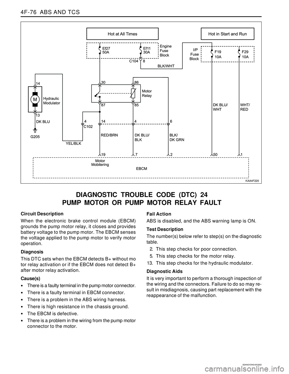
DIAGNOSTIC TROUBLE CODE (DTC) 24
PUMP MOTOR OR PUMP MOTOR RELAY FAULT
KAA4F220
Circuit Description
When the electronic brake control module (EBCM)
grounds the pump motor relay, it closes and provides
battery voltage to the pump motor. The EBCM senses
the voltage applied to the pump motor to verify motor
operation.
Diagnosis
This DTC sets when the EBCM detects B+ without mo
tor relay activation or if the EBCM does not detect B+
after motor relay activation.
Cause(s)
There is a faulty terminal in the pump motor connector.
There is a faulty terminal in EBCM connector.
There is a problem in the ABS wiring harness.
There is high resistance in the chassis ground.
The EBCM is defective.
There is a problem in the wiring from the pump motor
connector to the motor.Fail Action
ABS is disabled, and the ABS warning lamp is ON.
Test Description
The number(s) below refer to step(s) on the diagnostic
table.
2. This step checks for poor connection.
5. This step checks for the motor relay.
13. This step checks for the hydraulic modulator.
Diagnostic Aids
It is very important to perform a thorough inspection of
the wiring and the connectors. Failure to do so may re-
sult in misdiagnosis, causing part replacement with the
reappearance of the malfunction.
Page 1063 of 2053

SSANGYONG MY2002
4F-80 ABS AND TCS
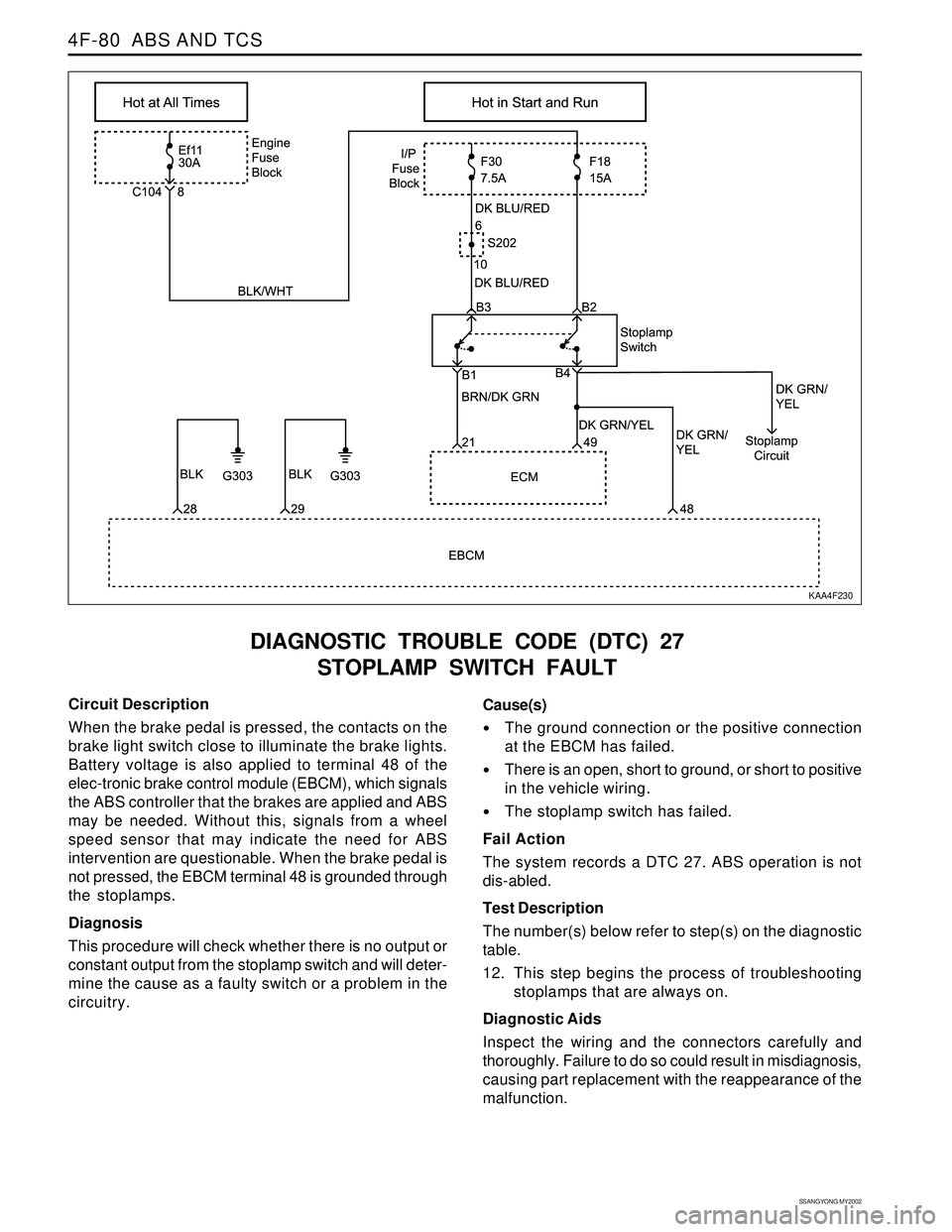
DIAGNOSTIC TROUBLE CODE (DTC) 27
STOPLAMP SWITCH FAULT
KAA4F230
Circuit Description
When the brake pedal is pressed, the contacts on the
brake light switch close to illuminate the brake lights.
Battery voltage is also applied to terminal 48 of the
elec-tronic brake control module (EBCM), which signals
the ABS controller that the brakes are applied and ABS
may be needed. Without this, signals from a wheel
speed sensor that may indicate the need for ABS
intervention are questionable. When the brake pedal is
not pressed, the EBCM terminal 48 is grounded through
the stoplamps.
Diagnosis
This procedure will check whether there is no output or
constant output from the stoplamp switch and will deter-
mine the cause as a faulty switch or a problem in the
circuitry.Cause(s)
The ground connection or the positive connection
at the EBCM has failed.
There is an open, short to ground, or short to positive
in the vehicle wiring.
The stoplamp switch has failed.
Fail Action
The system records a DTC 27. ABS operation is not
dis-abled.
Test Description
The number(s) below refer to step(s) on the diagnostic
table.
12. This step begins the process of troubleshooting
stoplamps that are always on.
Diagnostic Aids
Inspect the wiring and the connectors carefully and
thoroughly. Failure to do so could result in misdiagnosis,
causing part replacement with the reappearance of the
malfunction.
Page 1067 of 2053

SSANGYONG MY2002
4F-84 ABS AND TCS
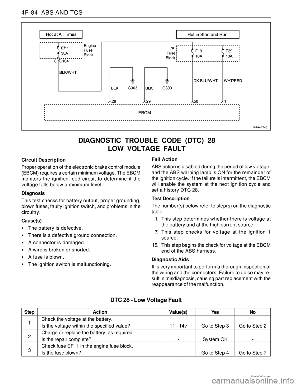
DIAGNOSTIC TROUBLE CODE (DTC) 28
LOW VOLTAGE FAULT
KAA4F240
Circuit Description
Proper operation of the electronic brake control module
(EBCM) requires a certain minimum voltage. The EBCM
monitors the ignition feed circuit to determine if the
voltage falls below a minimum level.
Diagnosis
This test checks for battery output, proper grounding,
blown fuses, faulty ignition switch, and problems in the
circuitry.
Cause(s)
The battery is defective.
There is a defective ground connection.
A connector is damaged.
A wire is broken or shorted.
A fuse is blown.
The ignition switch is malfunctioning.Fail Action
ABS action is disabled during the period of low voltage,
and the ABS warning lamp is ON for the remainder of
the ignition cycle. If the failure is intermittent, the EBCM
will enable the system at the next ignition cycle and
set a history DTC 28.
Test Description
The number(s) below refer to step(s) on the diagnostic
table.
1. This step determines whether there is voltage at
the battery and at the high current source.
7. This step checks for voltage at the ignition 1
source.
15. This step begins the check for voltage at the EBCM
end of the ABS harness.
Diagnostic Aids
It is very important to perform a thorough inspection of
the wiring and the connectors. Failure to do so may re-
sult in misdiagnosis, causing part replacement with the
reappearance of the malfunction.
Step
1
2
3
Action
Go to Step 3
System OK
Go to Step 4Go to Step 2
-
Go to Step 7 11 - 14v
-
-
Check the voltage at the battery.
Is the voltage within the specified value?
Charge or replace the battery, as required.
Is the repair complete?
Check fuse EF11 in the engine fuse block.
Is the fuse blown?
DTC 28 - Low Voltage Fault
Value(s) Yes No
Page 1078 of 2053
ABS AND TCS 4F-95
SSANGYONG MY2002
EBCM CONNECTION FACE VIEW
(WITHOUT TRACTION CONTROL SYSTEM)
EBCM CONNECTOR
KAA4F300
Color
BLK/DK GRN
BRN/BLK
-
BRN/WHT
BRN/BLK
BLK/RED
BRN/RED
BRN/YEL
BLK/DK GRN
YEL
BRN/DK GRN
-
RED/YEL
DK GRN/YEL
WHT/RED
BLK Pin
1
2
3
4
5
6
7
8
9
10
11
12
13
14
15
16Circuit
Right Rear Ground
Right Rear Sensor
Not Used
Right Front Ground
Right Front Sensor
Left Front Ground
Left Front Sensor
Left Rear Ground
Left Rear Sensor
Acceleration Sensor
Signal Voltage
Data Link Connector
Not Used
Torque On Demand
Stoplamp Switch
Ignition
GroundColor
RED/WHT
RED/WHT
-
BLK
LT GRN
DK GRN/BRN
-
-
-
-
-
RED
-
DK BLU
- Pin
17
18
19
20
21
22
23
24
25
26
27
28
29
30
31Circuit
Battery
Battery
Ground
ABS Warning Lamp
EBD Warning Lamp
Not Used
Not Used
Not Used
Not Used
Not Used
Not Used
Acceleration Sensor
Supply Voltage
Not Used
Acceleration Sensor
Ground
Not Used