Page 1496 of 2053
SSANGYONG MY2002
6E-10 POWER STEERING AND COLUMN
KAA6E060
KAA6E080
KAA6E070
WIPER SWITCH AND LEVER
Removal and Installation Procedure
1. Disconnect the negative battery cable.
2. Remove the upper and the lower steering column
cover screws.
3. Remove the upper and the lower steering column
cover.
4. Remove the wiper switch and lever mounting
mounting screws.
Tightening Torque 65 Nm (48 lb-ft) 5. Disconnect the wiper switch and lever connector.
6. Remove the wiper switch and lever.
STEERING WHEEL WITH SIR
Tools Required
661 589 00 33 00 Steering Wheel Puller
Removal and Installation Procedure
1. Disconnect the negative battery cable.
2. Remove the SIR module. Refer to Section 8B, Sup-
plemental Inflatable Restraints.
3. Remove the steering wheel nut.
Removal Notice:
In order to install the steering wheel correctly,
match mark the steering column shaft to the
steering wheel.
Installation Notice
Page 1497 of 2053
POWER STEERING AND COLUMN 6E-11
SSANGYONG MY2002
KAA6E040
KAA6E100
KAA6E090
4. Remove the steering wheel using the steering
wheel puller 661 589 00 33 00.
Installation Notice:
Align the match marks on the steering wheel
and the steering column shaft.
IGNITION LOCK CYLINDER AND
SWITCH
Removal and Installation Procedure
1. Disconnect the negative battery cable.
2. Remove the upper and the lower steering column
cover screws.
3. Remove the upper and the lower steering column
cover.
4. Remove the screws for illumination keyhole
connection.
5. With the key in the ignition turned to the position
designated ACC, remove the lock cylinder by
pressing down the detent spring with a 2.5 mm
allen wrench or other suitable tool, and pulling the
lock cylinder out of the cylinder housing.
Page 1498 of 2053
SSANGYONG MY2002
6E-12 POWER STEERING AND COLUMN
KAA6E040
KAA6E120
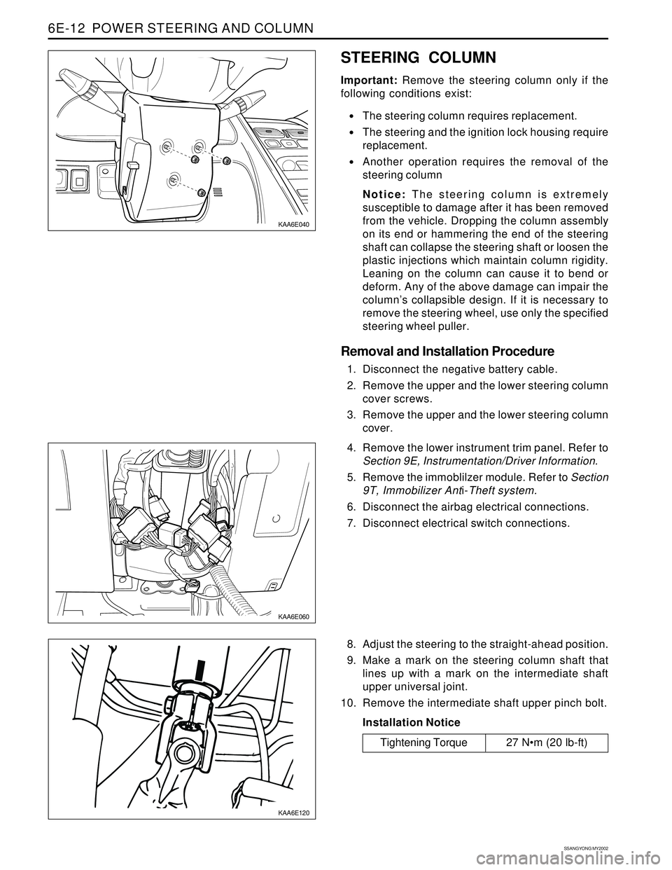
STEERING COLUMN
Important: Remove the steering column only if the
following conditions exist:
The steering column requires replacement.
The steering and the ignition lock housing require
replacement.
Another operation requires the removal of the
steering column
Notice: The steering column is extremely
susceptible to damage after it has been removed
from the vehicle. Dropping the column assembly
on its end or hammering the end of the steering
shaft can collapse the steering shaft or loosen the
plastic injections which maintain column rigidity.
Leaning on the column can cause it to bend or
deform. Any of the above damage can impair the
column’s collapsible design. If it is necessary to
remove the steering wheel, use only the specified
steering wheel puller.
Removal and Installation Procedure
1. Disconnect the negative battery cable.
2. Remove the upper and the lower steering column
cover screws.
3. Remove the upper and the lower steering column
cover.
KAA6E060
4. Remove the lower instrument trim panel. Refer to
Section 9E, Instrumentation/Driver Information.
5. Remove the immoblilzer module. Refer to Section
9T, Immobilizer Anti-Theft system.
6. Disconnect the airbag electrical connections.
7. Disconnect electrical switch connections.
8. Adjust the steering to the straight-ahead position.
9. Make a mark on the steering column shaft that
lines up with a mark on the intermediate shaft
upper universal joint.
10. Remove the intermediate shaft upper pinch bolt.
Installation Notice
Tightening Torque 27 Nm (20 lb-ft)
Page 1519 of 2053
SSANGYONG MY2002
7A-18 HEATING AND VENTILATION SYSTEM
ON-VEHICLE SERVICE
TEMPREATURE CONTROL CABLE
ADJUSTMENT
Because the cable and the cable housing have fixed
lengths, it is impossible to make a temperature cable
adjustment.
The heater/air distributor case linkage also cannot be
adjusted.
If a malfunction is suspected, verify the proper
operation of the controller and the mechanical doors
for heater/air distributor case assembly.
MAINTENANCE AND REPAIR
KAA7A020
KAA7A030
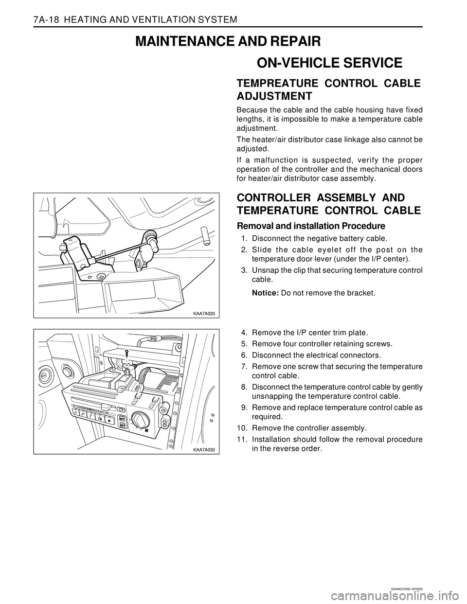
CONTROLLER ASSEMBLY AND
TEMPERATURE CONTROL CABLE
Removal and installation Procedure
1. Disconnect the negative battery cable.
2. Slide the cable eyelet off the post on the
temperature door lever (under the I/P center).
3. Unsnap the clip that securing temperature control
cable.
Notice: Do not remove the bracket.
4. Remove the I/P center trim plate.
5. Remove four controller retaining screws.
6. Disconnect the electrical connectors.
7. Remove one screw that securing the temperature
control cable.
8. Disconnect the temperature control cable by gently
unsnapping the temperature control cable.
9. Remove and replace temperature control cable as
required.
10. Remove the controller assembly.
11. Installation should follow the removal procedure
in the reverse order.
Page 1520 of 2053
HEATING AND VENTILATION SYSTEM 7A-19
SSANGYONG MY2002
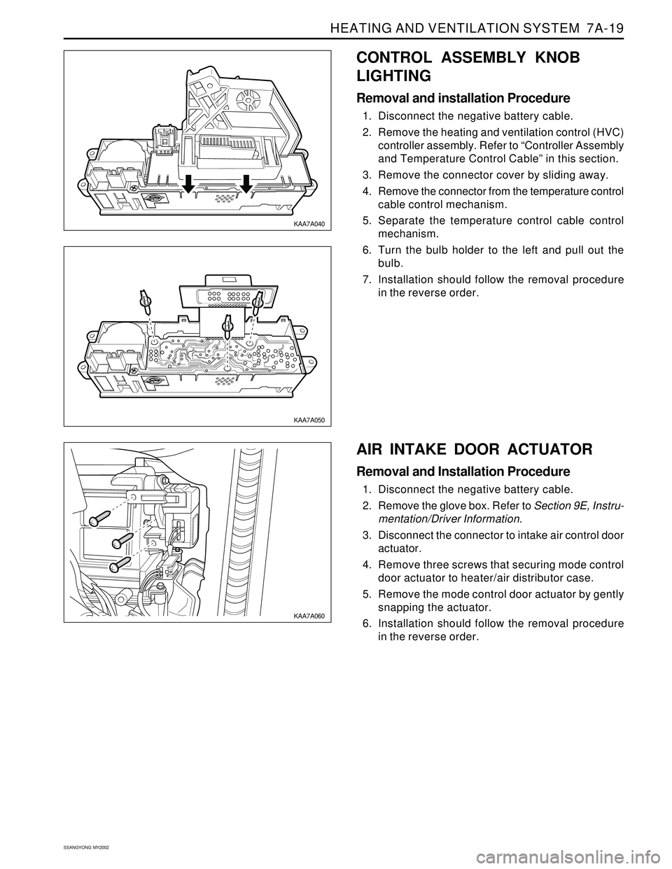
CONTROL ASSEMBLY KNOB
LIGHTING
Removal and installation Procedure
1. Disconnect the negative battery cable.
2. Remove the heating and ventilation control (HVC)
controller assembly. Refer to “Controller Assembly
and Temperature Control Cable” in this section.
3. Remove the connector cover by sliding away.
4. Remove the connector from the temperature control
cable control mechanism.
5. Separate the temperature control cable control
mechanism.
6. Turn the bulb holder to the left and pull out the
bulb.
7. Installation should follow the removal procedure
in the reverse order.
KAA7A040
KAA7A050
KAA7A060
AIR INTAKE DOOR ACTUATOR
Removal and Installation Procedure
1. Disconnect the negative battery cable.
2. Remove the glove box. Refer to Section 9E, Instru-
mentation/Driver Information.
3. Disconnect the connector to intake air control door
actuator.
4. Remove three screws that securing mode control
door actuator to heater/air distributor case.
5. Remove the mode control door actuator by gently
snapping the actuator.
6. Installation should follow the removal procedure
in the reverse order.
Page 1521 of 2053
SSANGYONG MY2002
7A-20 HEATING AND VENTILATION SYSTEM
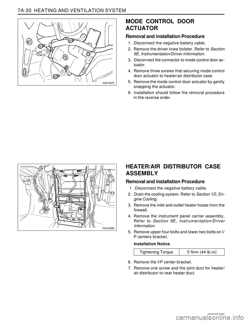
MODE CONTROL DOOR
ACTUATOR
Removal and installation Procedure
1. Disconnect the negative battery cable.
2. Remove the driver knee bolster. Refer to Section
9E, Instrumentation/Driver Information.
3. Disconnect the connector to mode control door ac-
tuator.
4. Remove three sxrews that securing mode control
door actuator to heater/air distributor case.
5. Remove the mode control door actuator by gently
snapping the actuator.
6. Installation should follow the removal procedure
in the reverse order.
Tightening Torque 5 Nm (44 lb-in)
KAA7A070
KAA7A080
HEATER/AIR DISTRIBUTOR CASE
ASSEMBLY
Removal and installation Procedure
1 .Disconnect the negative battery cable.
2. Drain the cooling system. Refer to Section 1D, En-
gine Cooling.
3. Remove the inlet and outlet heater hoses from the
firewall.
4. Remove the instrument panel carrier assembly.
Refer to Section 9E, Instrumentation/Driver
Information.
5. Remove upper four bolts and lower two bolts on I/
P centers bracket.
Installation Notice
6. Remove the I/P center bracket.
7. Remove one screw and the joint duct for heater/
air distributor-to-rear heater duct.
Page 1522 of 2053
HEATING AND VENTILATION SYSTEM 7A-21
SSANGYONG MY2002
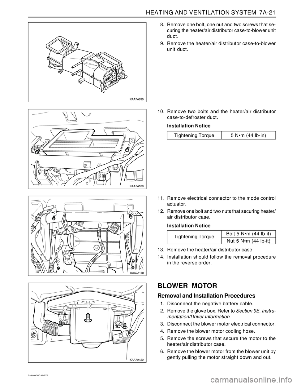
8. Remove one bolt, one nut and two screws that se-
curing the heater/air distributor case-to-blower unit
duct.
9. Remove the heater/air distributor case-to-blower
unit duct.
KAA7A090
KAA7A100
KAA7A110
KAA7A120
10. Remove two bolts and the heater/air distributor
case-to-defroster duct.
Installation Notice
11. Remove electrical connector to the mode control
actuator.
12. Remove one bolt and two nuts that securing heater/
air distributor case.
Installation Notice
13. Remove the heater/air distributor case.
14. Installation should follow the removal procedure
in the reverse order.
Tightening TorqueBolt 5 Nm (44 lb-it)
Nut 5 Nm (44 lb-it)
BLOWER MOTOR
Removal and Installation Procedures
1. Disconnect the negative battery cable.
2. Remove the glove box. Refer to Section 9E, Instru-
mentation/Driver Information.
3. Disconnect the blower motor electrical connector.
4. Remove the blower motor cooling hose.
5. Remove the screws that secure the motor to the
heater/air distributor case.
6. Remove the blower motor from the blower unit by
gently pulling the motor straight down and out.
Tightening Torque 5 Nm (44 lb-in)
Page 1523 of 2053
SSANGYONG MY2002
7A-22 HEATING AND VENTILATION SYSTEM
7. Installation should follow the removal procedure
in the reverse order.
Installation Notice: After install the blower motor
confirm that the blower motor operates properly.
KAA7A130
KAA7A140
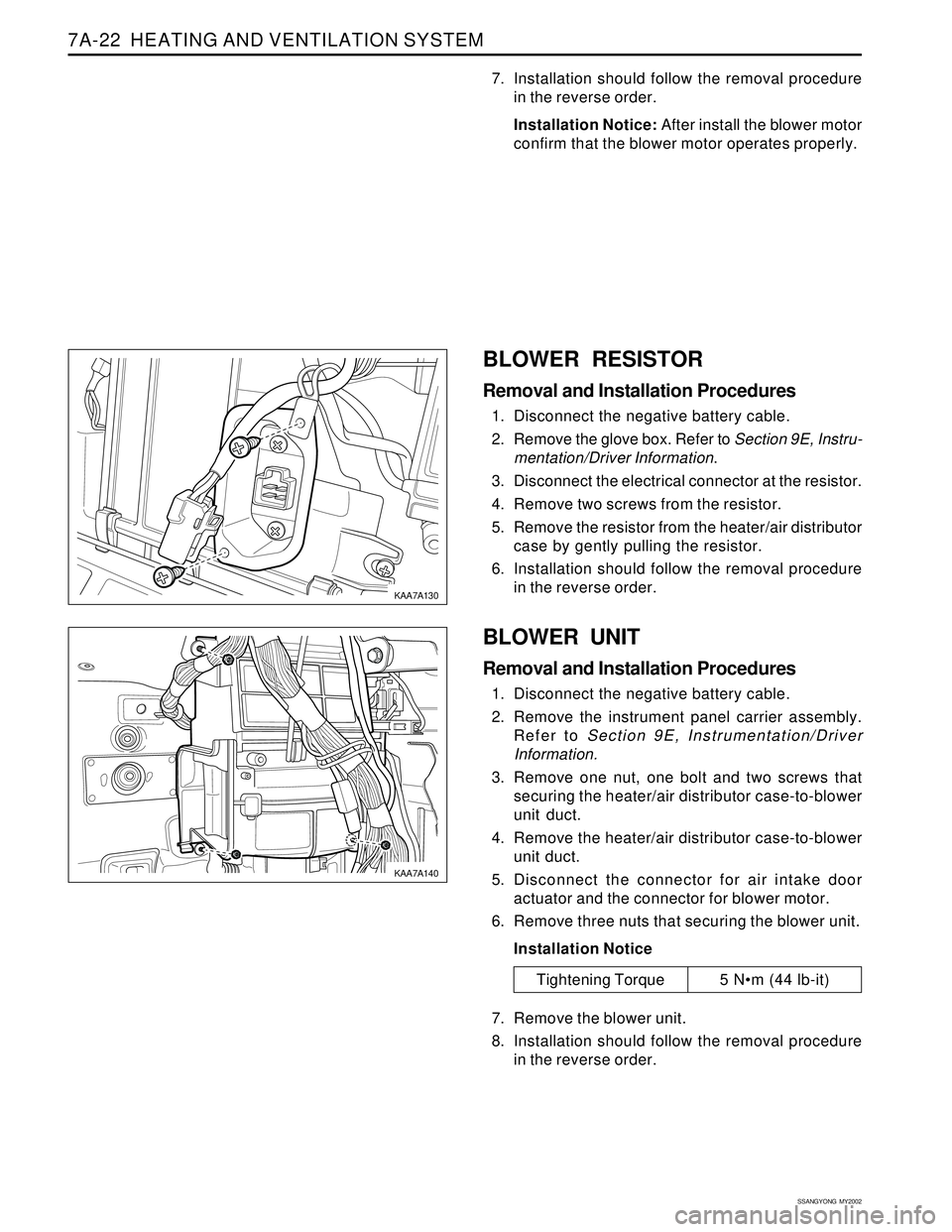
BLOWER RESISTOR
Removal and Installation Procedures
1. Disconnect the negative battery cable.
2. Remove the glove box. Refer to Section 9E, Instru-
mentation/Driver Information.
3. Disconnect the electrical connector at the resistor.
4. Remove two screws from the resistor.
5. Remove the resistor from the heater/air distributor
case by gently pulling the resistor.
6. Installation should follow the removal procedure
in the reverse order.
BLOWER UNIT
Removal and Installation Procedures
1. Disconnect the negative battery cable.
2. Remove the instrument panel carrier assembly.
Refer to Section 9E, Instrumentation/Driver
Information.
3. Remove one nut, one bolt and two screws that
securing the heater/air distributor case-to-blower
unit duct.
4. Remove the heater/air distributor case-to-blower
unit duct.
5. Disconnect the connector for air intake door
actuator and the connector for blower motor.
6. Remove three nuts that securing the blower unit.
Installation Notice
7. Remove the blower unit.
8. Installation should follow the removal procedure
in the reverse order.
Tightening Torque 5 Nm (44 lb-it)