Page 1525 of 2053

SSANGYONG MY2002
7A-24 HEATING AND VENTILATION SYSTEM
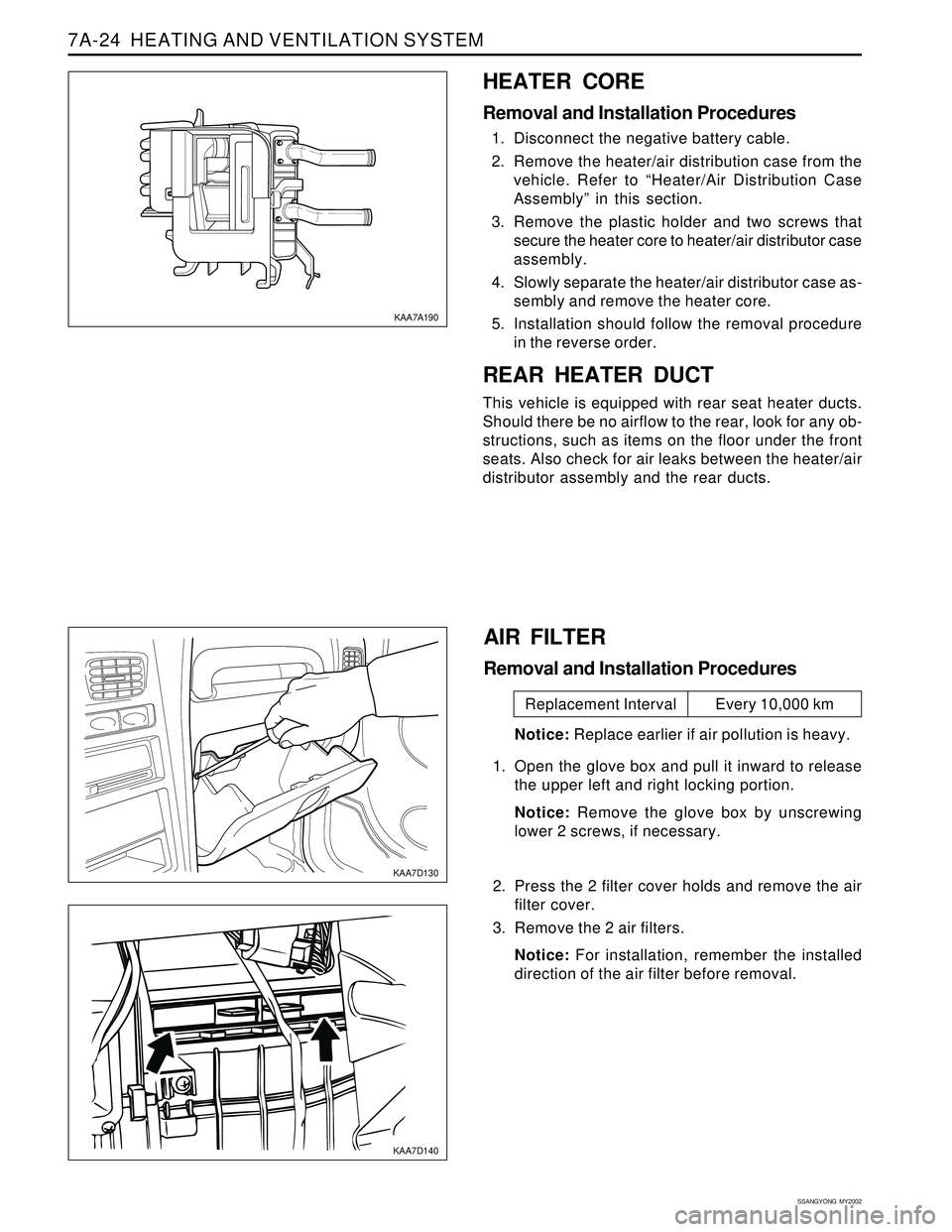
HEATER CORE
Removal and Installation Procedures
1. Disconnect the negative battery cable.
2. Remove the heater/air distribution case from the
vehicle. Refer to “Heater/Air Distribution Case
Assembly” in this section.
3. Remove the plastic holder and two screws that
secure the heater core to heater/air distributor case
assembly.
4. Slowly separate the heater/air distributor case as-
sembly and remove the heater core.
5. Installation should follow the removal procedure
in the reverse order.
REAR HEATER DUCT
This vehicle is equipped with rear seat heater ducts.
Should there be no airflow to the rear, look for any ob-
structions, such as items on the floor under the front
seats. Also check for air leaks between the heater/air
distributor assembly and the rear ducts.
KAA7A190
KAA7D130
KAA7D140
AIR FILTER
Removal and Installation Procedures
Notice: Replace earlier if air pollution is heavy.
1. Open the glove box and pull it inward to release
the upper left and right locking portion.
Notice: Remove the glove box by unscrewing
lower 2 screws, if necessary.
2. Press the 2 filter cover holds and remove the air
filter cover.
3. Remove the 2 air filters.
Notice: For installation, remember the installed
direction of the air filter before removal.
Replacement Interval Every 10,000 km
Page 1530 of 2053

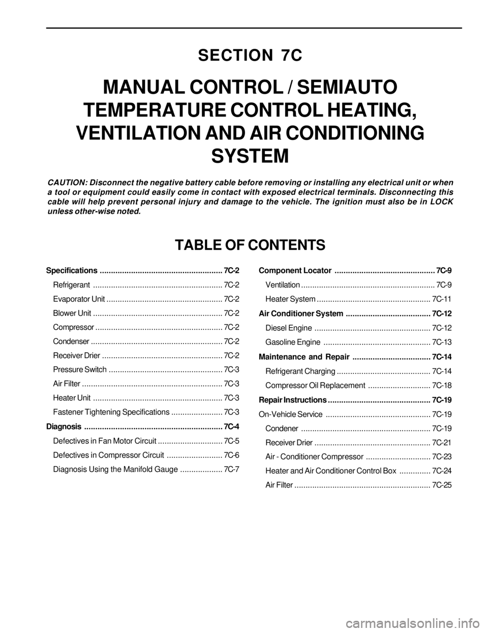
SECTION 7C
MANUAL CONTROL / SEMIAUTO
TEMPERATURE CONTROL HEATING,
VENTILATION AND AIR CONDITIONING
SYSTEM
CAUTION: Disconnect the negative battery cable before removing or installing any electrical unit or when
a tool or equipment could easily come in contact with exposed electrical terminals. Disconnecting this
cable will help prevent personal injury and damage to the vehicle. The ignition must also be in LOCK
unless other-wise noted.
TABLE OF CONTENTS
Specifications.......................................................7C-2
Refrigerant..........................................................7C-2
Evaporator Unit....................................................7C-2
Blower Unit..........................................................7C-2
Compressor.........................................................7C-2
Condenser...........................................................7C-2
Receiver Drier......................................................7C-2
Pressure Switch...................................................7C-3
Air Filter...............................................................7C-3
Heater Unit..........................................................7C-3
Fastener Tightening Specifications.......................7C-3
Diagnosis..............................................................7C-4
Defectives in Fan Motor Circuit.............................7C-5
Defectives in Compressor Circuit.........................7C-6
Diagnosis Using the Manifold Gauge...................7C-7Component Locator.............................................7C-9
Ventilation............................................................7C-9
Heater System ................................................... 7C-11
Air Conditioner System...................................... 7C-12
Diesel Engine .................................................... 7C-12
Gasoline Engine................................................ 7C-13
Maintenance and Repair................................... 7C-14
Refrigerant Charging .......................................... 7C-14
Compressor Oil Replacement............................ 7C-18
Repair Instructions.............................................. 7C-19
On-Vehicle Service............................................... 7C-19
Condener.......................................................... 7C-19
Receiver Drier.................................................... 7C-21
Air - Conditioner Compressor............................. 7C-23
Heater and Air Conditioner Control Box.............. 7C-24
Air Filter............................................................. 7C-25
Page 1533 of 2053

SSANGYONG MY2002
7C-4 MANUAL & SEMIAUTO-HVAC
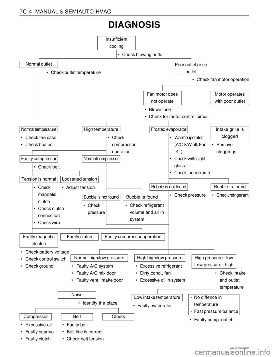
DIAGNOSIS
Insufficient
cooling
Check blowing outlet
Normal outlet
Check outlet temperature
Check fan motor operation
Motor operates
with poor outletFan motor does
not operate
Blown fuse
Check for motor control circuit
Poor outlet or no
outlet
Intake grille is
cloggedFrosted evaporatorHigh temperatureNormal temperature
Check the case
Check heater Check
compressor
operation Warmeaporator
(A/C S/W off, Fan
‘4’)
Check with sight
glass
Check thermo amp Remove
cloggings
Normal compressorFaulty compressor
Check belt
Tension is normal
Check
magnetic
clutch
Check clutch
connection
Check wire Adjust tension
Bubble is not foundBubble is found
Check refrigerant
volume and air in
system Check
pressure
Loosened tension
Bubble is not foundBubble is found
Check refrigerant Check pressure
Faulty magnetic
electricFaulty clutchFaulty compressor operation
Check battery voltage
Check control switch
Check ground
Normal high/low pressureHigh high/low pressureHigh pressure : low
Low pressure : high
Check intake
and outlet
temperature Faulty A/C system
Faulty A/C mix door
Faulty vent, intake door Excessive refrigerant
Dirty cond., fan
Excessive oil in system
- No diffence in
temperature
- Fast pressure balanceLow intake temperature
Faulty comp. outlet Faulty evaporatorNoise
CompressorBeltOthers
Excessive oil
Faulty bearing
Faulty clutch Identify the place
Faulty belt
Belt line is correct
Check belt tension
Page 1534 of 2053
MANUAL & SEMIAUTO-HVAC 7C-5
SSANGYONG MY2002
DEFECTIVES IN FAN MOTOR CIRCUIT
Fan Motor Does Not Run
Blown fuse
Battery voltage is low
Faulty wiring
Faulty groundChecksActionCheck for short and replace fuse.
Check battery voltage.
Check connectors’ connection.
Do not apply grease. This can cause voltage down.
Remove body painting and completely ground,
Tighten ground bolts and make sure body ground
connection.
Fan Motor Runs in ‘4’position Only (‘3’, ‘2’, ‘1’ : Does Not Run)
Motor Runs With Poor Blowing
Blown resister temperature fuse
Air leakage in parts connectionChecksActionReplace resistor.
Check heater, cooling unit and blower for proper
connection.
Clogged or blocked intake grilleChecksActionClogged or blocked intake grille reduces blowing
capacity.
Frosted Evaporator
Faulty thermo ampChecksActionFrosted evaporator reduces cooling capacity.
Off compressor and maximize blowing capacity
Page 1535 of 2053
SSANGYONG MY2002
7C-6 MANUAL & SEMIAUTO-HVAC
Oily clutch plate
Low voltage
Faulty electric connection or operationChecksActionClean oily plate using cleaning agent.
Charge battery or check for cause.
Check wire continuity
Check A/C switch and fan switch for continuity and
ground.
Magnetic Clutch Plays By Hand Only
Excessive clearance between
Clutch plate and clutch coilChecksActionAdjust clutch clearance (0.2-0.6mm).
DEFECTIVES IN COMPRESSOR CIRCUIT
Compressor Does Not Run
Faulty high/low pressure
Faulty A/C relayChecksActionCheck compressor magnet voltage supply.
A/C relay.
Magnetic Clutch Slips / Idles
Page 1551 of 2053
SSANGYONG MY2002
7C-22 MANUAL & SEMIAUTO-HVAC
3. Disconnect the inlet and outlet pipes of receiver
drier.
Notice: When installing, check the O-ring and
apply the compressor oil.
Installation Notice
4. Remove the bracket bolt and then remove the
receiver drier.
Installation Notice
5. Installation should follow the removal procedure
in the reverse order.
KAA7C250
Removal & Installation Procedure
1. Disconnect the negative(-) terminal from the
battery.
2. Discharge refrigerant from the system.
Notice: By connecting a manifold gauge
connection hose to High/Low pressure line,
discharge the refrigerant.
Tightening Torque4 - 6 Nm
(35 - 53 lb-in)
Tightening Torque5 - 8 Nm
(44 - 71 lb-in)
Page 1552 of 2053
MANUAL & SEMIAUTO-HVAC 7C-23
SSANGYONG MY2002
KAA7C260
1 Compressor Bracket
2 High Pressure Hose3 Low Pressure Hose
4 Compressor
AIR-CONDITIONER COMPRESSOR
Removal & Installation Procedure
1. Disconnect the negative (-) terminal from the
battery.
2. Discharge refrigerant from the system.
Notice: By connecting a manifold gauge
connection hose to High/Low pressure line,
discharge the refrigerant.
3. Disconnect the high/low pressure pipe and wire
connectors.
4. Remove the mounting bolt from the compressor
bracket and remove compressor assembly.
Notice: Place the removed compressor in vertical
position.
5. Installation should follow the removal procedure
in the reverse order.
KAA7C270
KAA7C280
Page 1568 of 2053
SSANGYONG MY2002
7D-14 FATC-HAVC
Rheostat
Tail lamp
Battery (+)
Power TR (B)
Power TR (C)
Temperature actuator (CCW)
IG2
Ground
Airconditioner switch ground
HI speed relay
Photo sensor (+)
Photo sensor (-)
Temperature actuator F/B
Temperature actuator (CW)
IG2
Ground Connection circuit
Pin Number and Connection Circuit
KAA7D080
Pin No.
1
2
3
4
5
6
7
8
9
10
11
12
13
14
15
16 Connector A Connector B
Incar sensor (+)
Ambient sensor (+)
Coolant sensor (+)
Sensor voltage 5V
Sensor ground
Intake (ambient)
Intake (incar)
-
-
-
VENT
B/L
FLR
MIX
DEF
-
-
-
-
- Connection circuit
Pin No.
1
2
3
4
5
6
7
8
9
10
11
12
13
14
15
16
17
18
19
20