Page 630 of 1503
Intake Ai r Syste m
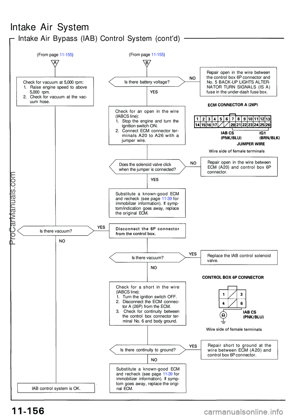
Intake Ai r Bypas s (IAB ) Contro l Syste m (cont'd )
(From pag e 11-155 )
Chec k fo r vacuu m at 5,00 0 rpm :
1 . Rais e engin e spee d t o abov e
5,00 0 rpm .
2 . Chec k fo r vacuu m a t th e vac -
uu m hose .
I s ther e vacuum ?
IA B contro l syste m is OK . I
s ther e batter y voltage ?
Chec k fo r a n ope n i n th e wir e
(IABC S line) :
1 . Sto p th e engin e an d tur n th e
ignitio n switc h ON .2. Connec t EC M connecto r ter -minal s A2 0 t o A2 6 wit h ajumpe r wire .
Doe s th e solenoi d valv e clic k
whe n th e jumpe r i s connected ?
Substitut e a known-goo d EC M
an d rechec k (se e pag e 11-3 9 fo r
immobilize r information) . I f symp -
tom/indicatio n goe s away , replac e
th e origina l ECM .
I s ther e vacuum ?
Chec k fo r a shor t i n th e wir e
(IABC S line) :
1 . Tur n th e ignitio n switc h OFF .
2. Disconnec t th e EC M connec -tor A (26P ) fro m th e ECM .
3 . Chec k fo r continuit y betwee n
th e contro l bo x connecto r ter -
mina l No . 6 an d bod y ground .
I s ther e continuit y t o ground ?
Substitut e a known-goo d EC M
an d rechec k (se e pag e 11-3 9 fo r
immobilize r information) . I f symp -
to m goe s away , replac e th e origi -
nal ECM .
Repai r ope n i n th e wir e betwee n
th e contro l bo x 6 P connecto r an d
No . 5 BACK-U P LIGHT S ALTER -
NATO R TUR N SIGNAL S (I S A )
fus e in th e under-das h fus e box .
Repai r ope n i n th e wir e betwee n
EC M (A20 ) an d contro l bo x 6 P
connector .
Replac e th e IA B contro l solenoi d
valve.
Repai r shor t t o groun d a t th ewir e betwee n EC M (A20 ) an dcontro l bo x 6 P connector .
(Fro
m pag e 11-155 )
ProCarManuals.com
Page 632 of 1503
Emission Contro l Syste m
System Descriptio n
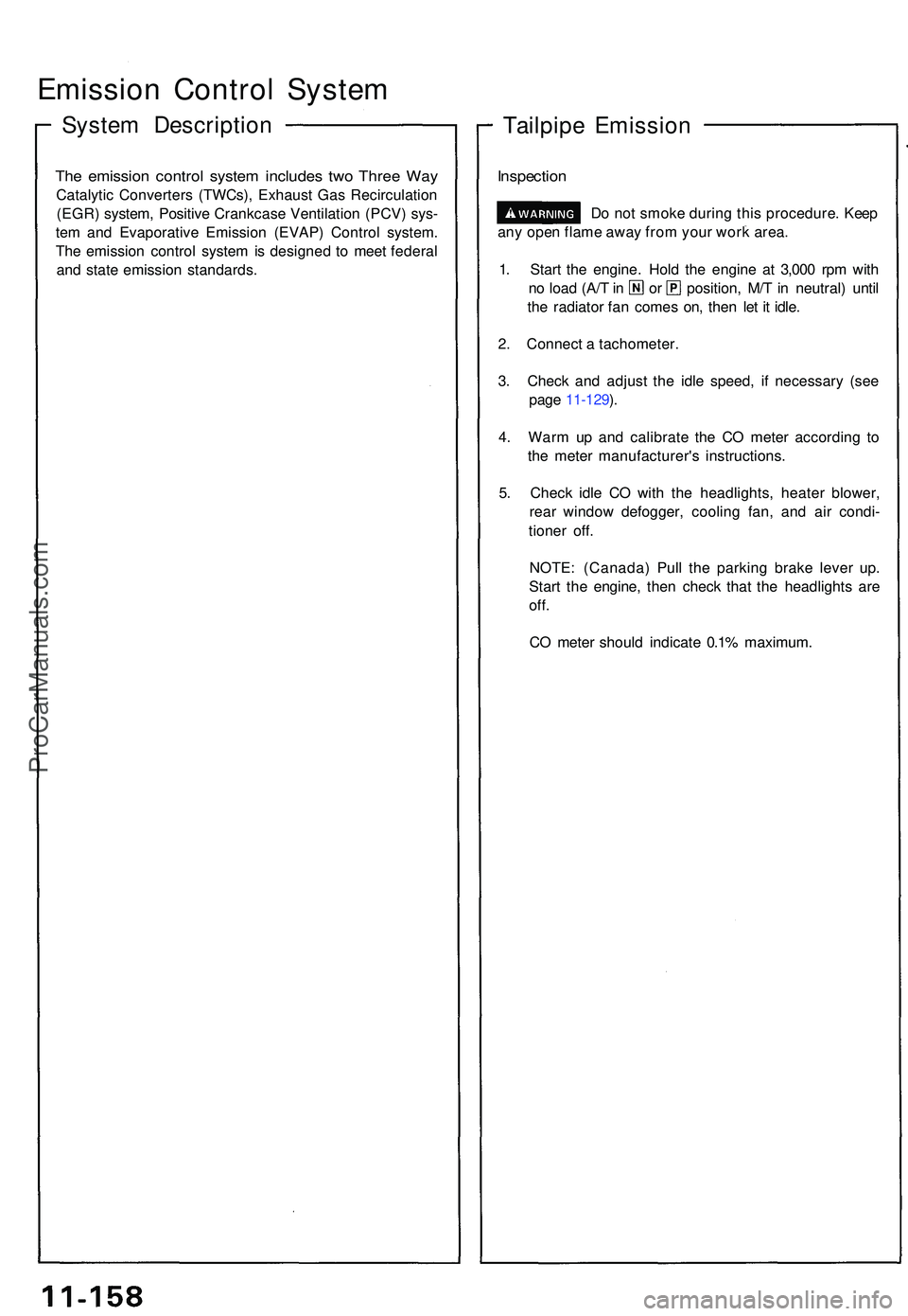
The emissio n contro l syste m include s tw o Thre e Wa y
Catalyti c Converter s (TWCs) , Exhaus t Ga s Recirculatio n
(EGR ) system , Positiv e Crankcas e Ventilatio n (PCV ) sys -
te m an d Evaporativ e Emissio n (EVAP ) Contro l system .
Th e emissio n contro l syste m is designe d t o mee t federa l
an d stat e emissio n standards .
Tailpipe Emissio n
1. Star t th e engine . Hol d th e engine at 3,00 0 rp m wit h
no loa d (A/ T in o r position , M/ T in neutral ) unti l
th e radiato r fa n come s on , the n le t i t idle .
2 . Connec t a tachometer .
3 . Chec k an d adjus t th e idl e speed , i f necessar y (se e
pag e 11-129 ).
4 . War m u p an d calibrat e th e C O mete r accordin g t o
th e mete r manufacturer' s instructions .
5 . Chec k idl e C O wit h th e headlights , heate r blower ,
rea r windo w defogger , coolin g fan , an d ai r condi -
tione r off .
NOTE : (Canada ) Pul l th e parkin g brak e leve r up .
Star t th e engine , the n chec k tha t th e headlight s ar e
off.
CO mete r shoul d indicat e 0.1 % maximum .
Inspection
any ope n flam e awa y fro m you r wor k area .
D
o no t smok e durin g thi s procedure . Kee p
ProCarManuals.com
Page 634 of 1503
Exhaust Gas Recirculation (EGR) System
The EGR system is designed to reduce oxides of nitrogen emissions (NOx) by recirculating exhaust gas through the EGR
valve and the intake manifold into the combustion chambers. It is composed of the EGR valve, EGR vacuum control valve,
EGR control solenoid valve, ECM and various sensors.
The ECM contains memories for ideal EGR valve lifts for varying operating conditions. The EGR valve lift sensor detects
the amount of EGR valve lift and sends the information to the ECM. The ECM then compares it with the ideal EGR valve lift
which is determined by signals sent from the other sensors. If there is any difference between the two, the ECM varies cur-
rent to the EGR control solenoid valve to regulate vacuum applied to the EGR valve.
EGR
VALVE
LIFT
SENSOR
INTAKE
MANIFOLD
EGR
CONTROL
SOLENOID
VALVE
To No. 5 BACK-UP
LIGHTS ALTERNATOR
TURN SIGNALS
(15 A) FUSE
-EGR
VACUUM
CONTROL
VALVE
(cont'd)
EGR
VALVE
VARIOUS
SENSORSProCarManuals.com
Page 635 of 1503
Emission Control System
Positive Crankcase Ventilation (PCV) System
Description
The Positive Crankcase Ventilation (PCV) system is
designed to prevent blow-by gas from escaping to the
atmosphere. The PCV valve contains a spring-loaded
plunger. When the engine starts, the plunger in the PCV
valve is lifted in proportion to intake manifold vacuum
and the blow-by gas is drawn directly into the intake
manifold.
PCV HOSE
INTAKE MANIFOLD
PCV VALVE
Inspection
1. Check the PCV hoses and connections for leaks and
clogging.
BREATHER
PIPE
PCV VALVE
PCV HOSE
2. At idle, make sure there is a clicking sound from the
PCV valve when the hose between PCV valve and
intake manifold in lightly pinched with your fingers
or pliers.
Gently pinch here
If there is no clicking sound, check the PCV valve
grommet for cracks or damage. If the grommet is
OK, replace the PCV valve and recheck.
BLOW-BY VAPOR
FRESH AIR
BREATHER PIPEProCarManuals.com
Page 636 of 1503
Evaporative Emission (EVAP) Controls
Description
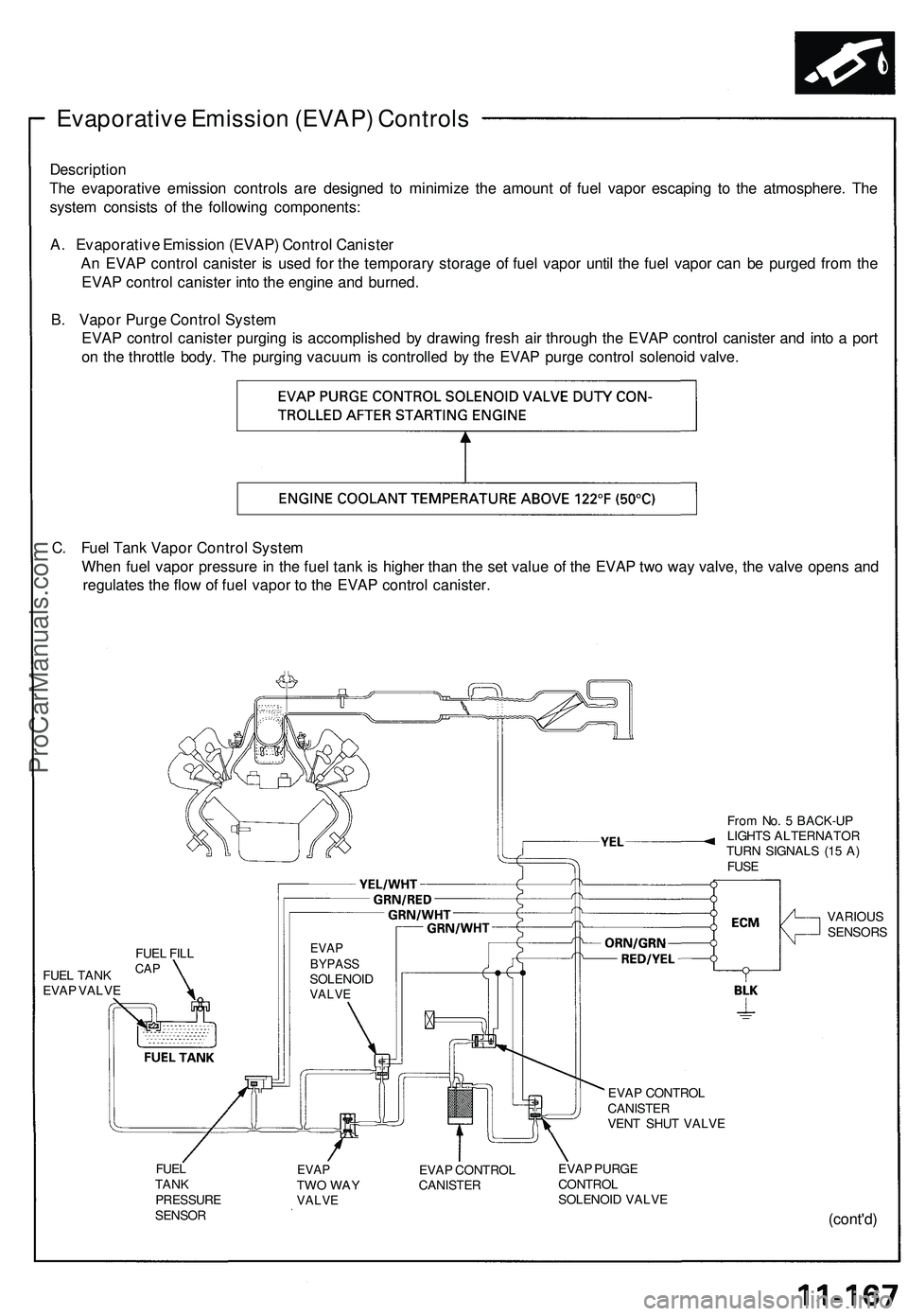
The evaporative emission controls are designed to minimize the amount of fuel vapor escaping to the atmosphere. The
system consists of the following components:
A. Evaporative Emission (EVAP) Control Canister
An EVAP control canister is used for the temporary storage of fuel vapor until the fuel vapor can be purged from the
EVAP control canister into the engine and burned.
B. Vapor Purge Control System
EVAP control canister purging is accomplished by drawing fresh air through the EVAP control canister and into a port
on the throttle body. The purging vacuum is controlled by the EVAP purge control solenoid valve.
C. Fuel Tank Vapor Control System
When fuel vapor pressure in the fuel tank is higher than the set value of the EVAP two way valve, the valve opens and
regulates the flow of fuel vapor to the EVAP control canister.
From No. 5 BACK-UP
LIGHTS ALTERNATOR
TURN SIGNALS (15 A)
FUSE
FUEL TANK
EVAP VALVE
EVAP
BYPASS
SOLENOID
VALVE
VARIOUS
SENSORS
EVAP CONTROL
CANISTER
VENT SHUT VALVE
FUEL
TANK
PRESSURE
SENSOR
EVAP
TWO WAY
VALVE
EVAP CONTROL
CANISTER
EVAP PURGE
CONTROL
SOLENOID VALVE
(cont'd)
FUEL FILL
CAPProCarManuals.com
Page 665 of 1503
BEARING OUTER RACE
75 mm THRUST SHIM
Selection.
CLAMP
BACK-UP LIGHT SWITCH
25 N-m (2.5 kgf-m, 18 Ibf-ft)
CLAMP
TRANSMISSION HANGER B
TRANSMISSION HANGER A
CLAMP
CLAMP
WASHER Replace.
OIL FILLER PLUG
44 N-m (4.5 kgf-m, 33 Ibf-ft)
42 x 63 x 12.5 mm OIL SEAL
Replace.
WASHER Replace.
DRAIN PLUG
39 N-m (4.0 kgf-m, 29 Ibf-ft)
36 mm SEALING BOLT
34 N-m (3.5 kgf-m, 25 Ibf-ft)
STRAINER COVER
O-RING Replace.
STRAINER SET SPRING
OIL PUMP STRAINER
14 mm SEALING BOLT
32 N-m (3.3 kgf-m, 24 Ibf-ft)
SPRING (L. 25 mm)
STEEL BALL (3/8 in)
REVERSE LOCKOUT SOLENOID
O-RING Replace.
SELECT LOCK PIN
SELECT LOCK RETURN SPRING
SELECT LOCK COLLAR
SPRING (L. 30 mm)
12 mm SEALING BOLT
22 N-m (2.2 kgf-m, 16 Ibf-ft)
STEEL BALL (5/16 in)
SHIFT LEVER ASSEMBLY
Removal, page 13-23
Installation, page 13-48
NEUTRAL POSITION SWITCH
25 N-m (2.5 kgf-m, 18 Ibf-ft)
TRANSMISSION HOUSING
OIL GUIDE PLATE
82 mm THRUST SHIM
Selection, page 13-46ProCarManuals.com
Page 714 of 1503
(cont'd)
Description
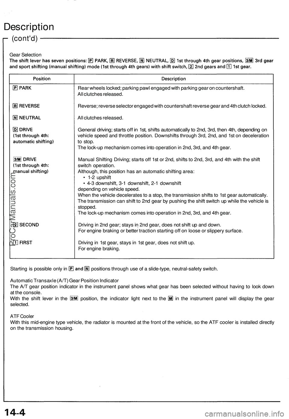
Gear Selection
Starting is possible only in positions through use of a slide-type, neutral-safety switch.
Automatic Transaxle (A/T) Gear Position Indicator
The A/T gear position indicator in the instrument panel shows what gear has been selected without having to look down
at the console.
With the shift lever in the position, the indicator light next to the in the instrument panel will display the gear
selected.
ATF Cooler
With this mid-engine type vehicle, the radiator is mounted at the front of the vehicle, so the ATF cooler is installed directly
on the transmission housing.
Rear wheels locked; parking pawl engaged with parking gear on countershaft.
All clutches released.
Reverse; reverse selector engaged with countershaft reverse gear and 4th clutch locked.
All clutches released.
General driving; starts off in 1st, shifts automatically to 2nd, 3rd, then 4th, depending on
vehicle speed and throttle position. Downshifts through 3rd, 2nd, and 1st on deceleration
to stop.
The lock-up mechanism comes into operation in 2nd, 3rd, and 4th gear.
Manual Shifting Driving; starts off 1st or 2nd, shifts to 2nd, 3rd, and 4th with the shift
switch operation.
Although, this position has an automatic shifting area:
• 1-2 upshift
• 4-3 downshift, 3-1 downshift, 2-1 downshift
depending on vehicle speed.
When the vehicle decelerates to a stop, the transmission shifts to 1st gear automatically.
The transmission can shift to 2nd gear by pushing the shift switch up while the vehicle is
stopped.
The lock-up mechanism comes into operation in 2nd, 3rd, and 4th gear.
Driving in 2nd gear; stays in 2nd gear, does not shift up and down.
For engine braking or better traction starting off on loose or slippery surface.
Driving in 1st gear, stays in 1st gear, does not shift up.
For engine braking.ProCarManuals.com
Page 750 of 1503
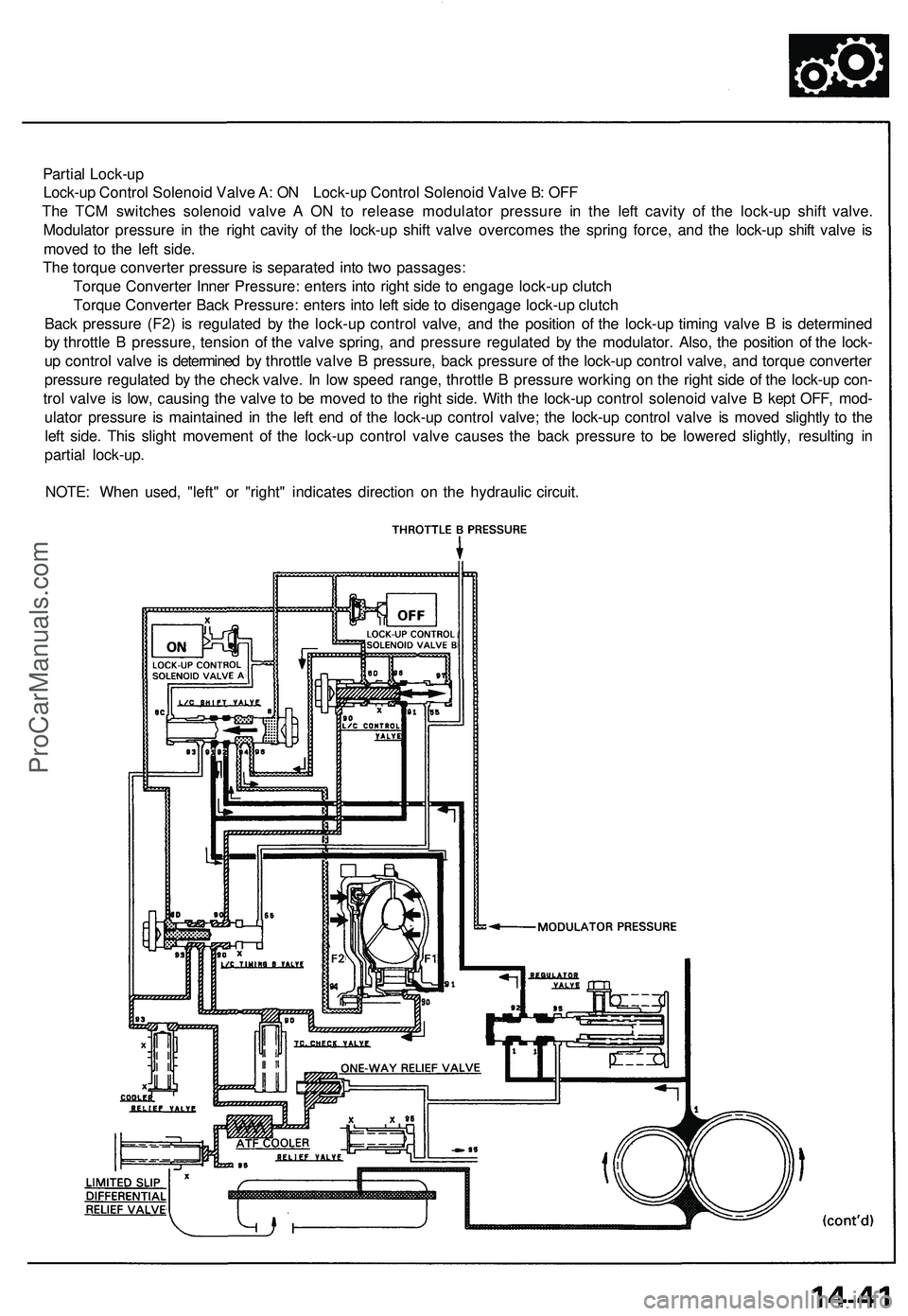
Partial Lock-up
Lock-up Control Solenoid Valve A: ON Lock-up Control Solenoid Valve B: OFF
The TCM switches solenoid valve A ON to release modulator pressure in the left cavity of the lock-up shift valve.
Modulator pressure in the right cavity of the lock-up shift valve overcomes the spring force, and the lock-up shift valve is
moved to the left side.
The torque converter pressure is separated into two passages:
Torque Converter Inner Pressure: enters into right side to engage lock-up clutch
Torque Converter Back Pressure: enters into left side to disengage lock-up clutch
Back pressure (F2) is regulated by the lock-up control valve, and the position of the lock-up timing valve B is determined
by throttle B pressure, tension of the valve spring, and pressure regulated by the modulator. Also, the position of the lock-
up control valve is determined by throttle valve B pressure, back pressure of the lock-up control valve, and torque converter
pressure regulated by the check valve. In low speed range, throttle B pressure working on the right side of the lock-up con-
trol valve is low, causing the valve to be moved to the right side. With the lock-up control solenoid valve B kept OFF, mod-
ulator pressure is maintained in the left end of the lock-up control valve; the lock-up control valve is moved slightly to the
left side. This slight movement of the lock-up control valve causes the back pressure to be lowered slightly, resulting in
partial lock-up.
NOTE: When used, "left" or "right" indicates direction on the hydraulic circuit.ProCarManuals.com