Page 909 of 1503

Troubleshooting Precautions
EPS Indicator Light
Under normal conditions, the EPS indicator light in the gauge assembly comes on when the ignition switch is turned to
the ON (II) position, then goes off after the engine is started. This indicates that the bulb and its circuits are operating cor-
rectly. If there is any trouble in the system, the EPS indicator light turns on during driving, and the power steering assist is
turned off. When the EPS indicator light comes on, the control unit memorizes the DTC. In this case, the control unit does
not activate the EPS system after the engine starts again but it keeps the EPS indicator light on.
Diagnostic Trouble Code (DTC)
• The lowest DTC is indicated first.
• The DTCs continue blinking until the ignition switch is turned off.
• The DTCs are erased from the control unit when the EPS control unit VBU power supply or connector is disconnected.
• The EPS system can be reset and the control unit's memory can be erased by disconnecting the CLOCK (7.5 A) fuse for
more than ten seconds.
Self-diagnosis:
The CPU (central processing unit) controls the following when it detects a problem during self-diagnosis:
1. Turns the EPS indicator light ON to alert the driver.
2. Power assist stops, and normal manual steering operation resumes (except DTC 33).
3. The EPS control unit memorizes the diagnostic trouble code (DTC).
4. After the DTC is stored in the control unit, the CPU stops self-diagnosis.
Troubleshooting:
• Before starting the troubleshooting, clear the DTC by disconnecting the CLOCK (7.5 A) fuse for ten seconds or more,
and test-drive the car. Check that the symptom of the trouble appears again, and then troubleshoot.
• When both EPS indicator light and A/T "D" indicator light come on, perform the A/T troubleshooting first.
• When the customer's reported problem cannot be verified in the car, ask the customer about the conditions when the
EPS indicator light came ON, then test-drive the car under those conditions, if possible. If the EPS indicator light does
not come ON during the test, check for loose connections or poor contacts at the connectors by wiggling the harness,
etc.
• The connector terminal numbers are viewed from the wire side for the female terminals and from the terminal side for
the male terminals.
• After the repair, test-drive the car and check that the EPS indicator light does not come ON again during the test. (Refer
to the Symptom-to-System Chart for diagnostic period.)ProCarManuals.com
Page 910 of 1503
Diagnostic Troubl e Cod e (DTC ) Indicatio n
1. Connec t th e SC S servic e connecto r t o th e servic e chec k connecto r unde r th e glov e box .
2 . Tur n th e ignitio n switc h O N (II) , bu t d o no t star t th e engine .
3 . Recor d th e blinkin g frequenc y o f th e EP S indicato r light . Th e blinkin g frequenc y indicate s th e diagnosti c troubl e cod e
(DTC) .
NOTE : Chec k th e DT C carefull y an d recor d it . Th e memor y o f th e DT C is erase d i f th e connecto r i s disconnecte d fro m
th e EP S contro l unit .
SCS SERVIC E CONNECTO R07PAZ-001010 0
SERVICE CHEC KCONNECTO R (2P )
ProCarManuals.com
Page 915 of 1503
Steering Wheel
Removal (cont'd)
7. Disconnect the connectors from the horn and cruise
control set/resume switches, then remove the cable
reel 3P connector from its clips.
8. Remove the steering wheel nut.
9. Remove the steering wheel by rocking it slightly
from side-to-side as you pull steadily with both
hands.ProCarManuals.com
Page 924 of 1503
Steering Colum n
Installatio n (cont'd )
12. Instal l th e dashboar d brac e an d dashboar d lowe r
pad.
13. Connec t th e foo t wel l ligh t harnes s an d light-o n
warnin g chim e t o th e dashboar d lowe r panel , the n
instal l th e dashboar d lowe r panel .
14 . Instal l th e steerin g whee l an d driver' s airba g assem -
bl y to th e colum n (se e pag e 17-45 ).
ProCarManuals.com
Page 927 of 1503
NOTE: Before removing the gearbox, place a stand jack
under the gearbox and front crossbeam to lightly sup-
port them. Lower the gearbox together with the front
crossbeam.
18. Remove the flange bolts and nuts of the gearbox
and front crossbeam.
19. Lower the gearbox and front crossbeam with care
so as not to hit or damage the radiator pipe.
NOTE: The crossbeam is attached to the crossbeam
bracket with locating pins. Remove the crossbeam
by lightly taping on it with a plastic hammer, then
remove the gearbox.
20. When installing the crossbeam to the crossbeam
bracket, be sure to align the holes in the crossbeam
with the locating pins on the crossbeam bracket.ProCarManuals.com
Page 932 of 1503

Steering Gearbo x
Inspectio n (cont'd )
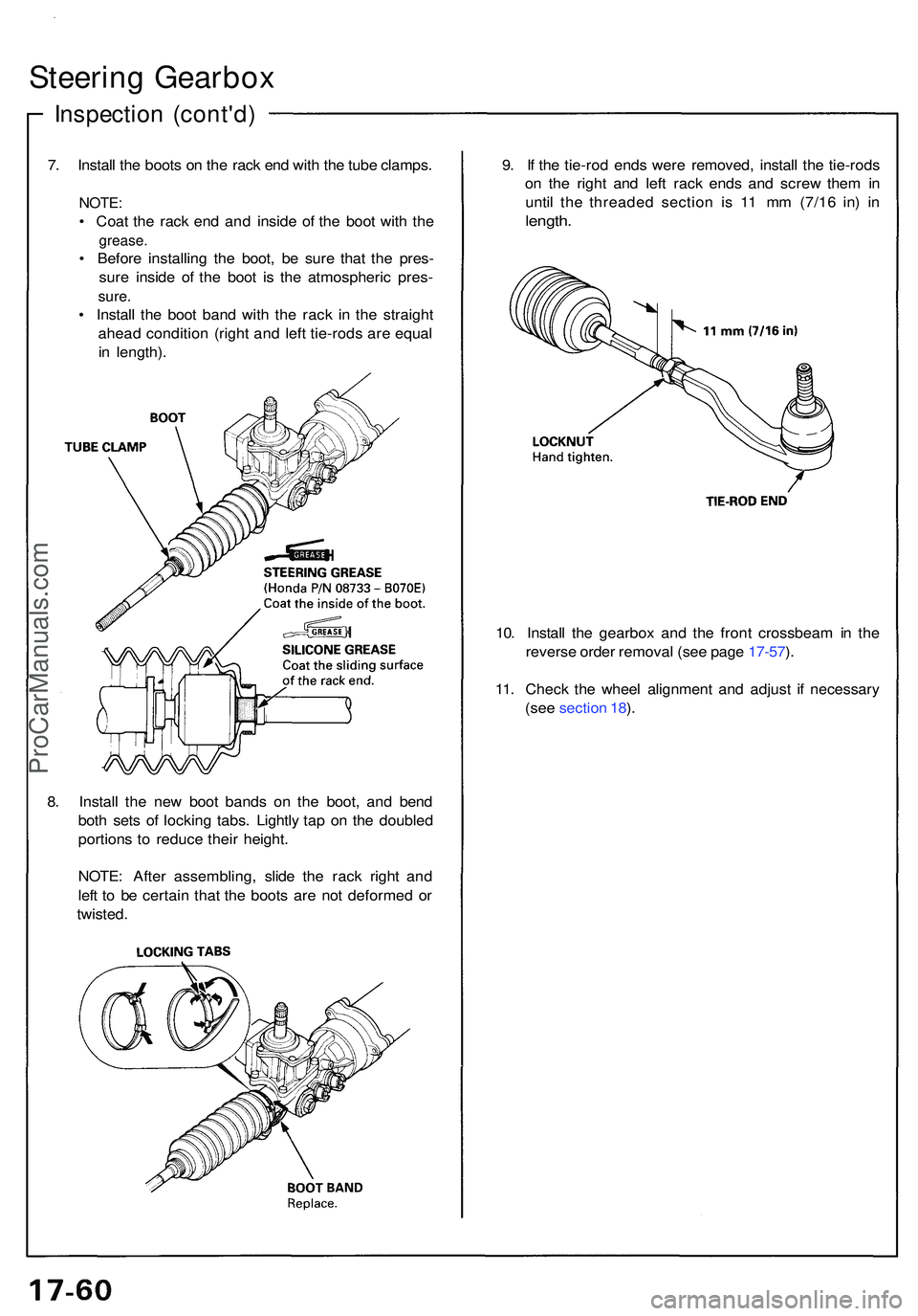
7. Instal l th e boot s o n th e rac k en d wit h th e tub e clamps .
NOTE:
• Coa t th e rac k en d an d insid e o f th e boo t wit h th e
grease .
• Befor e installin g th e boot , b e sur e tha t th e pres -
sur e insid e of the boo t i s th e atmospheri c pres -
sure.
• Instal l th e boo t ban d wit h th e rac k i n th e straigh t
ahea d conditio n (righ t an d lef t tie-rod s ar e equa l
i n length) . 9
. I f th e tie-ro d end s wer e removed , instal l th e tie-rod s
o n th e righ t an d lef t rac k end s an d scre w the m in
until the threade d sectio n i s 1 1 m m (7/1 6 in ) i n
length .
10. Instal l th e gearbo x an d th e fron t crossbea m in th e
revers e orde r remova l (se e pag e 17-57 ).
11 . Chec k th e whee l alignmen t an d adjus t i f necessar y
(se e sectio n 18 ).
8 . Instal l th e ne w boo t band s o n th e boot , an d ben d
bot h set s o f lockin g tabs . Lightl y ta p o n th e double d
portion s t o reduc e thei r height .
NOTE : Afte r assembling , slid e th e rac k righ t an d
lef t t o b e certai n tha t th e boot s ar e no t deforme d o r
twisted .
ProCarManuals.com
Page 937 of 1503

System Description
Suspension Composition
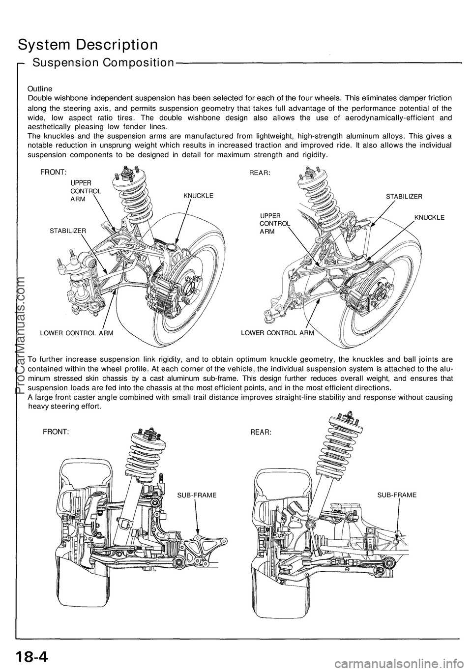
Outline
Double wishbon e independen t suspensio n ha s bee n selecte d fo r eac h o f th e fou r wheels . Thi s eliminate s dampe r frictio n
along th e steerin g axis , an d permit s suspensio n geometr y tha t take s ful l advantag e o f th e performanc e potentia l o f th e
wide , lo w aspec t rati o tires . Th e doubl e wishbon e desig n als o allow s th e us e o f aerodynamically-efficien t an d
aestheticall y pleasin g lo w fende r lines .
Th e knuckle s an d th e suspensio n arm s ar e manufacture d fro m lightweight , high-strengt h aluminu m alloys . Thi s give s a
notabl e reductio n i n unsprun g weigh t whic h result s i n increase d tractio n an d improve d ride . I t als o allow s th e individua l
suspensio n component s t o b e designe d i n detai l fo r maximu m strengt h an d rigidity .
FRONT:
UPPERCONTRO LARMKNUCKL E
STABILIZE R
REAR
STABILIZE R
UPPERCONTRO LARM
LOWE R CONTRO L AR M
KNUCKL E
LOWER CONTRO L AR M
To furthe r increas e suspensio n lin k rigidity , an d t o obtai n optimu m knuckl e geometry , th e knuckle s an d bal l joint s ar e
containe d withi n th e whee l profile . A t eac h corne r o f th e vehicle , th e individua l suspensio n syste m is attache d t o th e alu -
minu m stresse d ski n chassi s b y a cas t aluminu m sub-frame . Thi s desig n furthe r reduce s overal l weight , an d ensure s tha t
suspensio n load s ar e fe d int o th e chassi s a t th e mos t efficien t points , an d i n th e mos t efficien t directions .
A larg e fron t caste r angl e combine d wit h smal l trai l distanc e improve s straight-lin e stabilit y an d respons e withou t causin g
heav y steerin g effort .
FRONT :REAR:
SUB-FRAM ESUB-FRAM E
ProCarManuals.com
Page 938 of 1503

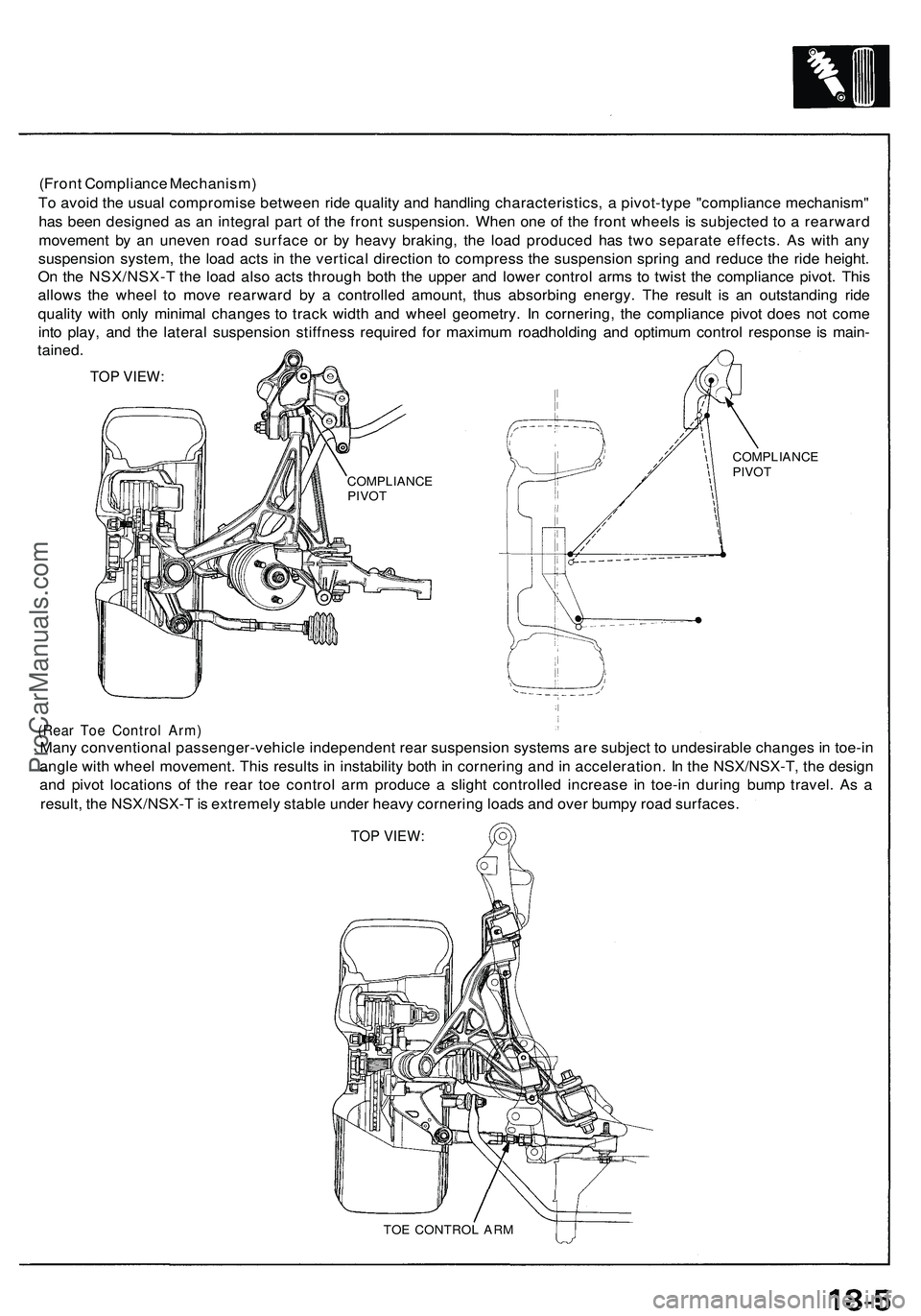
(Front Compliance Mechanism)
To avoid the usual compromise between ride quality and handling characteristics, a pivot-type "compliance mechanism"
has been designed as an integral part of the front suspension. When one of the front wheels is subjected to a rearward
movement by an uneven road surface or by heavy braking, the load produced has two separate effects. As with any
suspension system, the load acts in the vertical direction to compress the suspension spring and reduce the ride height.
On the NSX/NSX-T the load also acts through both the upper and lower control arms to twist the compliance pivot. This
allows the wheel to move rearward by a controlled amount, thus absorbing energy. The result is an outstanding ride
quality with only minimal changes to track width and wheel geometry. In cornering, the compliance pivot does not come
into play, and the lateral suspension stiffness required for maximum roadholding and optimum control response is main-
tained.
TOP VIEW:
(Rear Toe Control Arm)
Many conventional passenger-vehicle independent rear suspension systems are subject to undesirable changes in toe-in
angle with wheel movement. This results in instability both in cornering and in acceleration. In the NSX/NSX-T, the design
and pivot locations of the rear toe control arm produce a slight controlled increase in toe-in during bump travel. As a
result, the NSX/NSX-T is extremely stable under heavy cornering loads and over bumpy road surfaces.
TOP VIEW:
TOE CONTROL ARM
COMPLIANCE
PIVOT
COMPLIANCE
PIVOTProCarManuals.com