Page 271 of 1503
Lighting System
HID Lamp System Troubleshooting
1. Check the No. 49 (20 A) or No. 52 (20 A) fuse in the
main under-hood fuse/relay box.
Are the fuses OK?
YES — Go to step 2.
NO — Replace the fuse (s), and recheck.
2. Substitute a known-good HID bulb and recheck.
Does the headlight low beam come on?
YES — Replace the HID bulb.
NO — Go to step 3.
3. Disconnect the 2P connector from the inverter unit.
4. Turn the combination light switch ON.
5. Measure the voltage between the No. 2 terminal of
the inverter unit 2P connector and body ground.
7. Check for continuity between the No. 1 terminal of
the inverter unit 2P connector and body ground.
Is there continuity?
YES — Substitute a known-good inverter, and
recheck. If the symptom/indication goes away,
replace the original inverter unit.
NO — Repair open in the wire between the inverter
unit and body ground. If the wire is OK, check for
poor ground at G202 or G302.ProCarManuals.com
Page 272 of 1503
Headlight Low Beam Relay Test
1. Remove the headlight low beam relay from the
under-hood fuse/relay box.
2. Check continuity at the relay terminals.
• There should be continuity between the C and D
terminals.
• There should be continuity between the A and B
terminals when power and ground are connect-
ed to the C and D terminals.
• There should be no continuity between the A
and B terminals when power is disconnected.
Headlight High Beam/Dimmer
Relay (USA) Test
1. Remove the headlight high beam relay or the dimmer
relay (USA) from the under-hood fuse/relay box.
2. Check continuity at the relay terminals.
• There should be continuity between the C and D
terminals.
• There should be continuity between the A and B
terminals when power and ground are connect-
ed to the C and D terminals.
• There should be no continuity between the A and
B terminals when power is disconnected.
• Headlight high beam relay
• Dimmer relay (USA)ProCarManuals.com
Page 286 of 1503

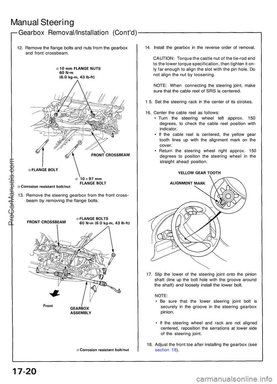
Gearbox Removal/Installatio n (Cont'd )
Manual Steerin g
12. Remov e th e flang e bolt s an d nut s fro m th e gearbo x
and fron t crossbeam . 14
. Instal l th e gearbo x i n th e revers e orde r o f removal .
CAUTION : Torqu e th e castl e nu t o f th e tie-ro d en d
t o th e lowe r torqu e specification , the n tighte n it on -
l y fa r enoug h to alig n th e slo t wit h th e pi n hole . D o
no t alig n th e nu t b y loosening .
NOTE : Whe n connectin g th e steerin g joint , mak e
sure tha t th e cabl e ree l o f SR S is centered .
1 5 . Se t th e steerin g rac k i n th e cente r o f it s strokes .
16 . Cente r th e cabl e ree l a s follows :
• Tur n th e steerin g whee l lef t approx . 15 0
degrees , t o chec k th e cabl e ree l positio n wit h
indicator .
• I f th e cabl e ree l i s centered , th e yello w gea r
toot h line s u p wit h th e alignmen t mar k o n th e
cover .
• Retur n th e steerin g whee l righ t approx . 15 0
degree s t o positio n th e steerin g whee l i n th e
straigh t ahea d position .
17 . Sli p th e lowe r o f th e steerin g join t ont o th e pinio n
shaf t (lin e u p th e bol t hol e wit h th e groov e aroun d
the shaft ) an d loosel y instal l th e lowe r bolt .
NOTE :
• B e sur e tha t th e lowe r steerin g join t bol t i s
securel y i n th e groov e i n th e steerin g gearbo x
pinion.
• I f th e steerin g whee l an d rac k ar e no t aligne d
centered , repositio n th e serration s a t lowe r sid e
of th e steerin g joint .
18 . Adjus t th e fron t to e afte r installin g th e gearbo x (se e
sectio n 18 ).
13
. Remov e th e steerin g gearbo x fro m th e fron t cross -
beam b y removin g th e flang e bolts .
ProCarManuals.com
Page 467 of 1503

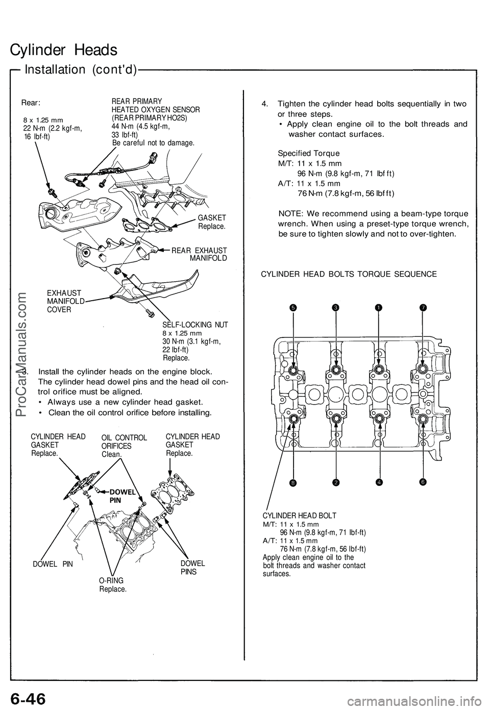
Cylinder Heads
Installation (cont'd)
Rear:
8 x
1.25
mm
22 N-m (2.2 kgf-m,
16 Ibf-ft)
REAR PRIMARY
HEATED OXYGEN SENSOR
(REAR PRIMARY HO2S)
44 N-m (4.5 kgf-m,
33 Ibf-ft)
Be careful not to damage.
GASKET
Replace.
REAR EXHAUST
MANIFOLD
EXHAUST
MANIFOLD
COVER
SELF-LOCKING NUT
8 x
1.25
mm
30 N-m (3.1 kgf-m,
22 Ibf-ft)
Replace.
3. Install the cylinder heads on the engine block.
The cylinder head dowel pins and the head oil con-
trol orifice must be aligned.
• Always use a new cylinder head gasket.
• Clean the oil control orifice before installing.
CYLINDER HEAD
GASKET
Replace.
OIL CONTROL
ORIFICES
Clean.
CYLINDER HEAD
GASKET
Replace.
DOWEL PIN
DOWEL
PINS
O-RING
Replace.
4. Tighten the cylinder head bolts sequentially in two
or three steps.
• Apply clean engine oil to the bolt threads and
washer contact surfaces.
Specified Torque
M/T:
11 x 1.5 mm
96 N-m (9.8 kgf-m, 71 Ibf ft)
A/T:
11 x 1.5 mm
76 N-m (7.8 kgf-m, 56 Ibf ft)
NOTE: We recommend using a beam-type torque
wrench. When using a preset-type torque wrench,
be sure to tighten slowly and not to over-tighten.
CYLINDER HEAD BOLTS TORQUE SEQUENCE
CYLINDER HEAD BOLT
M/T:
11 x 1.5 mm
96 N-m (9.8 kgf-m, 71 Ibf-ft)
A/T:
11 x 1.5 mm
76 N-m (7.8 kgf-m, 56 Ibf-ft)
Apply clean engine oil to the
bolt threads and washer contact
surfaces.ProCarManuals.com
Page 662 of 1503

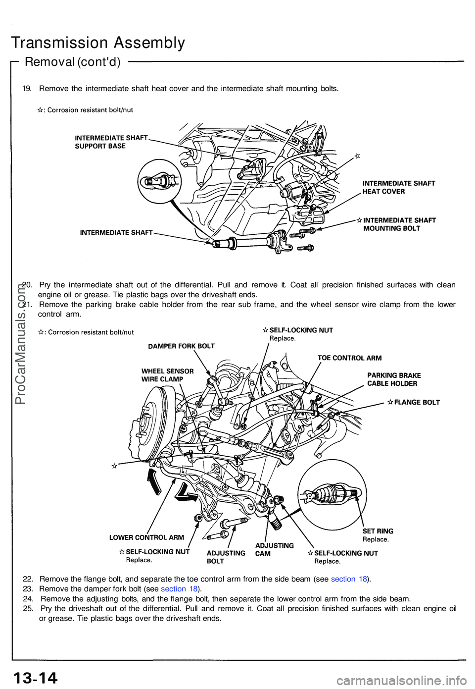
Transmission Assembl y
Removal (cont'd )
19. Remov e th e intermediat e shaf t hea t cove r an d th e intermediat e shaf t mountin g bolts .
20 . Pr y th e intermediat e shaf t ou t o f th e differential . Pul l an d remov e it . Coa t al l precisio n finishe d surface s wit h clea n
engin e oi l o r grease . Ti e plasti c bag s ove r th e driveshaf t ends .
21 . Remov e th e parkin g brak e cabl e holde r fro m th e rea r su b frame , an d th e whee l senso r wir e clam p fro m th e lowe r
contro l arm .
22 . Remov e th e flang e bolt , an d separat e th e to e contro l ar m fro m th e sid e bea m (se e sectio n 18 ).
23 . Remov e th e damper fork bol t (se e sectio n 18 ).
24 . Remov e th e adjustin g bolts , an d th e flang e bolt , the n separat e th e lowe r contro l ar m fro m th e sid e beam .
25 . Pr y th e driveshaf t ou t o f th e differential . Pul l an d remov e it . Coa t al l precisio n finishe d surfaces with clea n engin e oi l
o r grease . Ti e plasti c bag s ove r th e driveshaf t ends .
ProCarManuals.com
Page 779 of 1503
11. Remove the parking brake cable holders from the rear beam rod.
12. Remove the rear beam rod.
13. Remove the front exhaust pipe A.
14. Remove the parking brake cable holder and the wheel sensor wire clamp.
1 5. Make a reference mark on the flange of the adjusting bolt, adjusting cam and lower control arm.
16. Separate the toe control arm from the side beam.
17. Remove the damper fork bolt.
18. Separate the lower control arm from the side beam.
19. Remove the right driveshaft from the intermediate shaft.ProCarManuals.com
Page 780 of 1503
20. Remove the intermediate shaft heat shield cover and the intermediate shaft mounting bolts.
21. Pry the intermediate shaft out of the differential. Pull and remove it.
NOTE:
• Coat all precision finished surfaces with clean engine oil.
• Tie a plastic bag over the intermediate shaft end.
Removal (cont'd)
Transmission
22. Remove the parking brake cable holder and the wheel sensor wire clamp.
23. Make a reference mark on the flange of the adjusting bolt, adjusting cam and lower control arm.
24. Separate the toe control arm from the side beam.
25. Remove the damper fork bolt.
26. Separate the lower control arm from the side beam.
27. Pry the left driveshaft out of the differential. Pull and remove it.
NOTE:
• Coat all precision finished surfaces with clean engine oil.
• Tie a plastic bag over the driveshaft end.ProCarManuals.com
Page 836 of 1503
Installation (cont'd)
Transmission
11. Install a new set ring on the end of the left driveshaft and intermediate shaft. Apply a light film of grease around the
set ring grooves, then center the new set ring on the shafts. The grease keeps the set ring centered, making shaft
installation easier.
12. Install the left driveshaft.
13. Install the lower control arm to the side beam.
CAUTION: Line up the reference marks on the adjusting bolt, adjusting cam, and lower control arm.
14. Install the damper fork bolt.
15. Install the toe control arm to the side beam.
CAUTION: Make sure that the reference marks on the toe control arm are aligned.
16. Install the wheel sensor wire clamp and parking brake cable holder.
17. Install the intermediate shaft, and tighten the intermediate shaft mounting bolts to the intermediate shaft support
base.
18. Install the intermediate shaft heat shield cover.ProCarManuals.com