Page 193 of 1503
Radiator
Engine Coolant Refilling and Bleeding
CAUTION: When pouring engine coolant, be sure to
shut the relay box lid and not let coolant spill on the
electrical parts or the paint. If any coolant spills, rinse it
off immediately.
NOTE:
• Perform this maintenance when the engine is cool.
• Before replacing the coolant, turn the ignition ON,
slowly turn the climate control temperature knob to
90° and turn off the ignition. This will allow the
coolant in the heater to drain out with the rest of the
system.
1. Open the hood, the rear window and the engine
cover.
2. Remove the cover protecting the water pipes and
shift cables on the underside of the car.
3. Before removing the expansion tank cap, first
loosen the cap to lower pressure.
CAUTION: Do not remove the expansion tank cap
when engine is hot. The coolant is under pressure
and may blow out and scald you. Open the cap
slowly when the engine is cool.
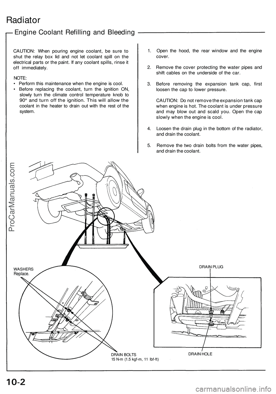
4. Loosen the drain plug in the bottom of the radiator,
and drain the coolant.
5. Remove the two drain bolts from the water pipes,
and drain the coolant.
DRAIN BOLTS
15 N-m (1.5 kgf-m, 11 Ibf-ft)
DRAIN HOLE
DRAIN PLUG
WASHERS
Replace.ProCarManuals.com
Page 412 of 1503
21. Disconnect the engine wire harness connectors.
22. Remove the battery cable from the main fuse box.
24. Disconnect the two connectors from the emission
control box, then remove the control box.
• Do not disconnect the vacuum hoses.
Removal (cont'd)
Engine Removal/Installation
23. Disconnect the throttle body 6P connector, and
remove the ground cable and starter cable.
25. Remove the radiator hoses and heater hose.ProCarManuals.com
Page 521 of 1503
Engine Coolant Refilling and Bleeding
CAUTION: When pouring engine coolant, be sure to
shut the relay box lid and not let coolant spill on the
electrical parts or the paint. If any coolant spills, rinse it
off immediately.
NOTE:
• Perform this maintenance when the engine is cool.
• Before replacing the coolant, turn the ignition ON,
slowly turn the climate control temperature knob to
90° and turn off the ignition. This will allow the
coolant in the heater to drain out with the rest of the
system.
1. Open the hood, the rear window and the engine
cover.
2. Remove the cover protecting the water pipes and
shift cables on the underside of the car.
3. Before removing the expansion tank cap, first
loosen the cap to lower pressure.
CAUTION: Do not remove the expansion tank cap
when engine is hot. The coolant is under pressure
and may blow out and scald you. Open the cap
slowly when the engine is cool.
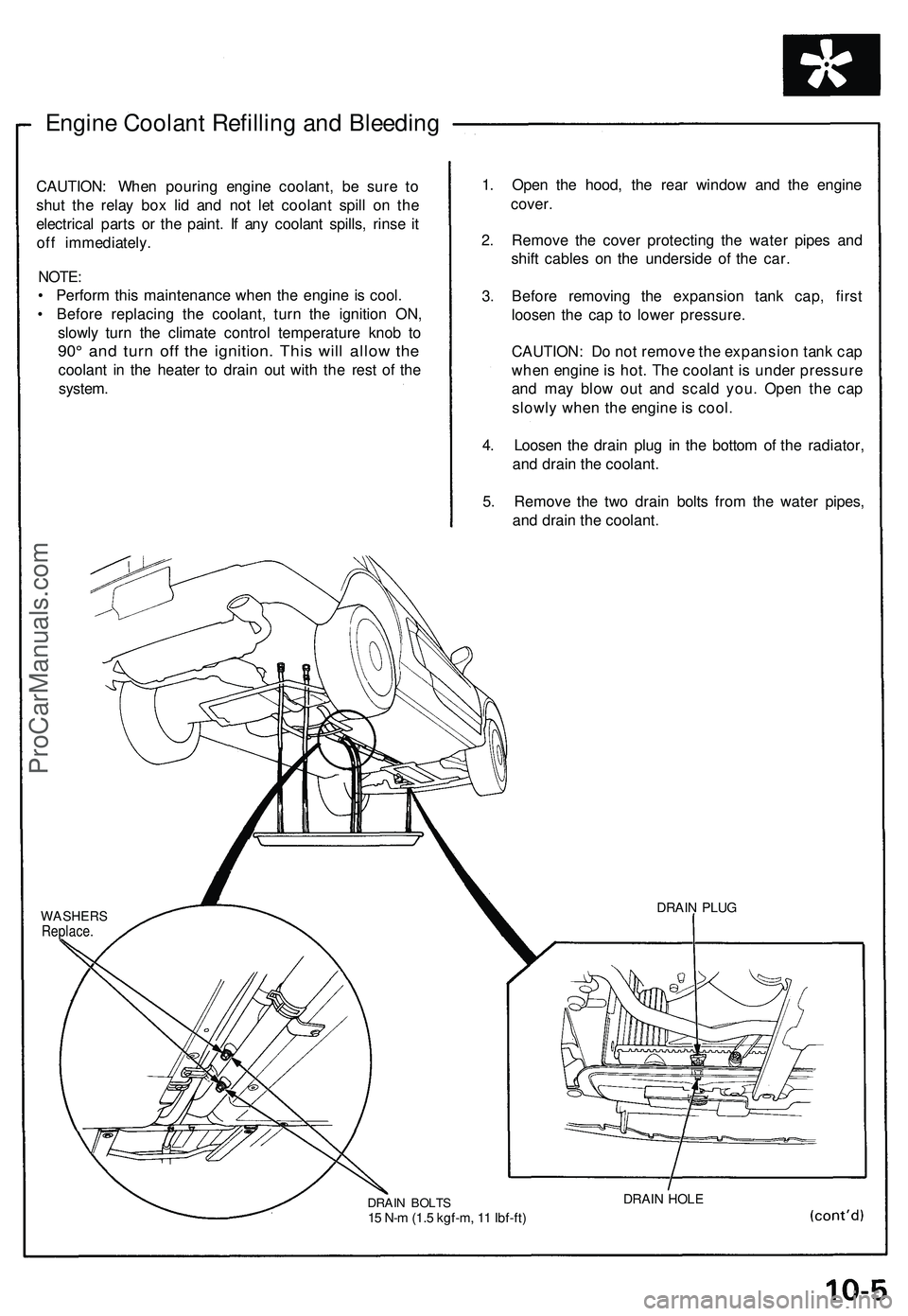
4. Loosen the drain plug in the bottom of the radiator,
and drain the coolant.
5. Remove the two drain bolts from the water pipes,
and drain the coolant.
WASHERS
Replace.
DRAIN BOLTS
15 N-m (1.5 kgf-m, 11 Ibf-ft)
DRAIN HOLE
DRAIN PLUGProCarManuals.com
Page 523 of 1503
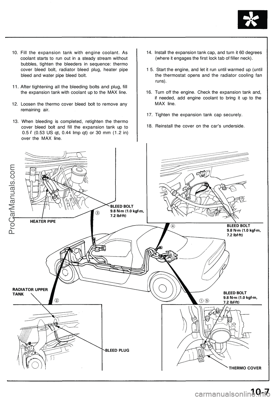
10. Fill the expansion tank with engine coolant. As
coolant starts to run out in a steady stream without
bubbles, tighten the bleeders in sequence: thermo
cover bleed bolt, radiator bleed plug, heater pipe
bleed and water pipe bleed bolt.
11. After tightening all the bleeding bolts and plug, fill
the expansion tank with coolant up to the MAX line.
12. Loosen the thermo cover bleed bolt to remove any
remaining air.
13. When bleeding is completed, retighten the thermo
cover bleed bolt and fill the expansion tank up to
0.5
(0.53
US qt,
0.44
Imp qt) or 30 mm
(1.2
in)
over the MAX line.
14. Install the expansion tank cap, and turn it 60 degrees
(where it engages the first lock tab of filler neck).
1 5. Start the engine, and let it run until warmed up (until
the thermostat opens and the radiator cooling fan
runs).
16. Turn off the engine. Check the expansion tank and,
if needed, add engine coolant to bring it up to the
MAX line.
17. Tighten the expansion tank cap securely.
18. Reinstall the cover on the car's underside.ProCarManuals.com
Page 572 of 1503
Troubleshooting
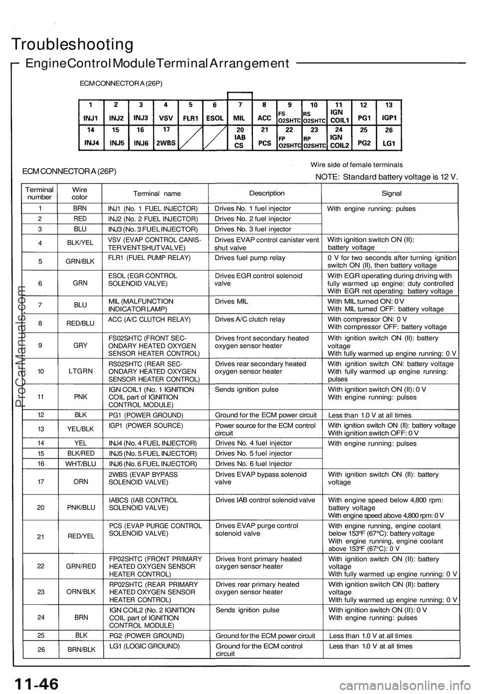
Engine Control Module Terminal Arrangement
ECM CONNECTOR A (26P)
ECM CONNECTOR A (26P)
Wire side of female terminals
NOTE: Standard battery voltage is 12 V.
Terminal
number
1
2
3
4
5
6
7
8
9
10
11
12
13
14
15
16
17
20
21
22
23
24
25
26
Wire
color
BRN
RED
BLU
BLK/YEL
GRN/BLK
GRN
BLU
RED/BLU
GRY
LTGRN
PNK
BLK
YEL/BLK
YEL
BLK/RED
WHT/BLU
ORN
PNK/BLU
RED/YEL
GRN/RED
ORN/BLK
BRN
BLK
BRN/BLK
Terminal name
INJ1 (No. 1 FUEL INJECTOR)
INJ2 (No. 2 FUEL INJECTOR)
INJ3 (No. 3 FUEL INJECTOR)
VSV (EVAP CONTROL CANIS-
TER VENT SHUT VALVE)
FLR1 (FUEL PUMP RELAY)
ESOL (EGR CONTROL
SOLENOID VALVE)
MIL (MALFUNCTION
INDICATOR LAMP)
ACC (A/C CLUTCH RELAY)
FS02SHTC (FRONT SEC-
ONDARY HEATED OXYGEN
SENSOR HEATER CONTROL)
RS02SHTC (REAR SEC-
ONDARY HEATED OXYGEN
SENSOR HEATER CONTROL)
IGN COIL1 (No. 1 IGNITION
COIL part of IGNITION
CONTROL MODULE)
PG1 (POWER GROUND)
IGP1 (POWER SOURCE)
INJ4 (No. 4 FUEL INJECTOR)
INJ5 (No. 5 FUEL INJECTOR)
INJ6 (No. 6 FUEL INJECTOR)
2WBS (EVAP BYPASS
SOLENOID VALVE)
IABCS (IAB CONTROL
SOLENOID VALVE)
PCS (EVAP PURGE CONTROL
SOLENOID VALVE)
FP02SHTC (FRONT PRIMARY
HEATED OXYGEN SENSOR
HEATER CONTROL)
RP02SHTC (REAR PRIMARY
HEATED OXYGEN SENSOR
HEATER CONTROL)
IGN COIL2 (No. 2 IGNITION
COIL part of IGNITION
CONTROL MODULE)
PG2 (POWER GROUND)
LG1 (LOGIC GROUND)
Description
Drives No. 1 fuel injector
Drives No. 2 fuel injector
Drives No. 3 fuel injector
Drives EVAP control canister vent
shut valve
Drives fuel pump relay
Drives EGR control solenoid
valve
Drives MIL
Drives A/C clutch relay
Drives front secondary heated
oxygen sensor heater
Drives rear secondary heated
oxygen sensor heater
Sends ignition pulse
Ground for the ECM power circuit
Power source for the ECM control
circuit
Drives No. 4 fuel injector
Drives No. 5 fuel injector
Drives No. 6 fuel injector
Drives EVAP bypass solenoid
valve
Drives IAB control solenoid valve
Drives EVAP purge control
solenoid valve
Drives front primary heated
oxygen sensor heater
Drives rear primary heated
oxygen sensor heater
Sends ignition pulse
Ground for the ECM power circuit
Ground for the ECM control
circuit
Signal
With engine running: pulses
With ignition switch ON (II):
battery voltage
0 V for two seconds after turning ignition
switch ON (II), then battery voltage
With EGR operating during driving with
fully warmed up engine: duty controlled
With EGR not operating: battery voltage
With MIL turned ON: 0V
With MIL turned OFF: battery voltage
With compressor ON: 0 V
With compressor OFF: battery voltage
With ignition switch ON (II): battery
voltage
With fully warmed up engine running: 0 V
With ignition switch ON: battery voltage
With fully warmed up engine running:
pulses
With ignition switch ON (II): 0 V
With engine running: pulses
Less than 1.0 V at all times
With ignition switch ON (II): battery voltage
With ignition switch OFF: 0 V
With engine running: pulses
With ignition switch ON (II): battery
voltage
With engine speed below 4,800 rpm:
battery voltage
With engine speed above 4,800 rpm: 0 V
With engine running, engine coolant
below 153°F (67°C): battery voltage
With engine running, engine coolant
above 153°F (67°C): 0 V
With ignition switch ON (II): battery
voltage
With fully warmed up engine running: 0 V
With ignition switch ON (II): battery
voltage
With fully warmed up engine running: 0 V
With ignition switch ON (II): 0 V
With engine running: pulses
Less than 1.0 V at all times
Less than 1.0 V at all timesProCarManuals.com
Page 1107 of 1503
Carpet
Replacement (cont'd)
5. Pull up the retainers, then remove the floor carpets.
6. Remove the console carpets.
FOOTREST
RETAINERS
FOOTREST MOUNTING
BOLTS
SEAT HARNESSES
7. Installation is the reverse of the removal procedure.
NOTE:
• Take care not to damage, wrinkle or twist the carpets.
• Make sure the air vents are connected, into the heater unit and air duct.
• Make sure the seat harnesses are routed correctly.
CONSOLE
CARPETS
RETAINERS
FLOOR CARPETS
SRS UNITProCarManuals.com
Page 1179 of 1503
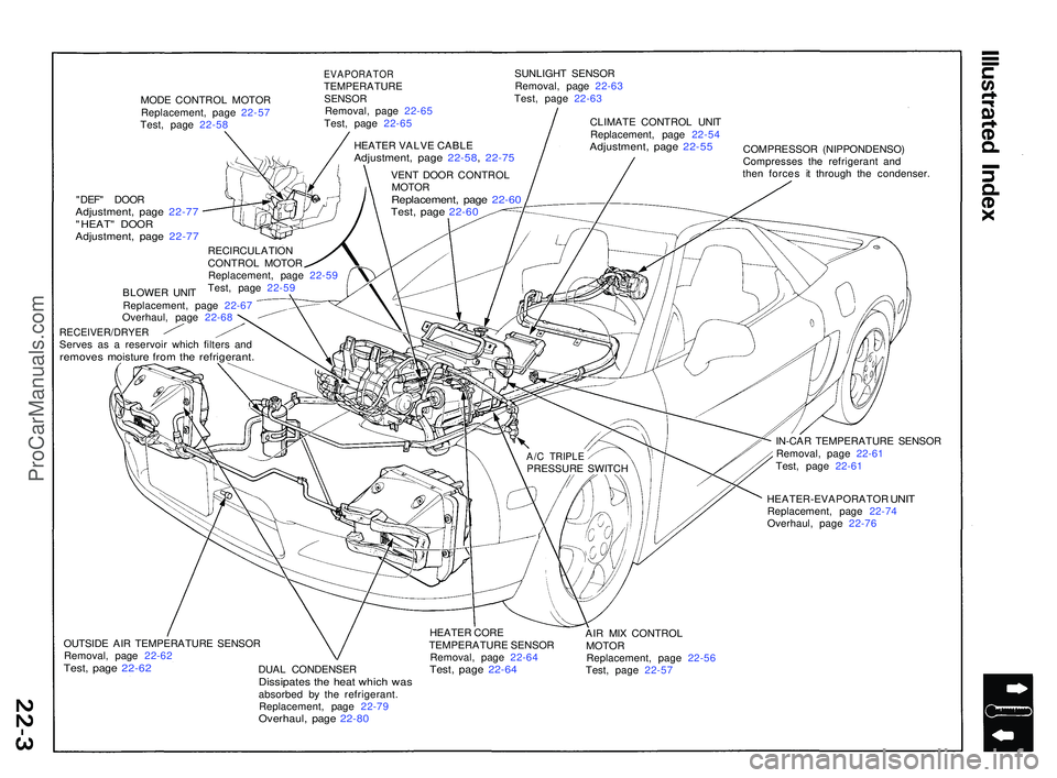
MODE CONTRO L MOTO R
Replacement , pag e 22-5 7
Test , pag e 22-5 8
EVAPORATO RTEMPERATUR ESENSORRemoval , pag e 22-6 5
Test , pag e 22-6 5 SUNLIGH
T SENSO R
Removal , pag e 22-6 3
Test , pag e 22-6 3
CLIMAT E CONTRO L UNI T
Replacement , pag e 22-5 4
Adjustment , pag e 22-5 5COMPRESSO R (NIPPONDENSO )
Compresse s th e refrigeran t an d
the n force s i t throug h th e condenser .
"DEF " DOO R
Adjustment , pag e 22-7 7"HEAT " DOO RAdjustment , pag e 22-7 7
BLOWE R UNI T
Replacement , pag e 22-6 7
Overhaul , pag e 22-6 8
RECEIVER/DRYE RServes a s a reservoi r whic h filter s an dremove s moistur e fro m th e refrigerant .
IN-CAR TEMPERATUR E SENSO R
Removal , pag e 22-6 1
Test , pag e 22-6 1
HEATER-EVAPORATO R
UNITReplacement , pag e 22-7 4
Overhaul , pag e 22-7 6
OUTSID E AI R TEMPERATUR E SENSO R
Removal , pag e 22-6 2
Test, pag e 22-6 2DUAL CONDENSE RDissipates th e hea t whic h wa sabsorbe d b y th e refrigerant .
Replacement , pag e 22-7 9
Overhaul , pag e 22-8 0
HEATE R COR E
TEMPERATUR E SENSO R
Removal , pag e 22-6 4
Test, pag e 22-6 4
AIR MI X CONTRO L
MOTO R
Replacement , pag e 22-5 6
Test , pag e 22-5 7
RECIRCULATIO
N
CONTRO L MOTO R
Replacement , pag e 22-5 9
Test , pag e 22-5 9 HEATE
R VALV E CABL E
Adjustment , pag e 22-58 , 22-7 5
VENT DOO R CONTRO L
MOTO R
Replacement , pag e 22-6 0Test, pag e 22-6 0
A/C TRIPL EPRESSUR E SWITC H
ProCarManuals.com
Page 1180 of 1503
Heater-Evaporator Door Position
(MAX COOL)
U.S.A model
VENT DOOR
DEFROSTER
DOOR
HEAT
DOOR
AIR MIX DOOR
HEATER CORE
A/C EVAPORATOR
COREProCarManuals.com