1997 ACURA NSX clock reset
[x] Cancel search: clock resetPage 130 of 1503
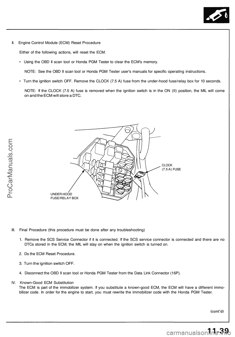
II. Engine Control Module (ECM) Reset Procedure
Either of the following actions, will reset the ECM.
• Using the OBD II scan tool or Honda PGM Tester to clear the ECM's memory.
NOTE: See the OBD II scan tool or Honda PGM Tester user's manuals for specific operating instructions.
• Turn the ignition switch OFF. Remove the CLOCK (7.5 A) fuse from the under-hood fuse/relay box for 10 seconds.
NOTE: If the CLOCK (7.5 A) fuse is removed when the ignition switch is in the ON (II) position, the MIL will come
on and the ECM will store a DTC.
UNDER-HOOD
FUSE/RELAY BOX
CLOCK
(7.5 A) FUSE
III. Final Procedure (this procedure must be done after any troubleshooting)
1. Remove the SCS Service Connector if it is connected. If the SCS service connector is connected and there are no
DTCs stored in the ECM, the MIL will stay on when the ignition switch is turned on.
2. Do the ECM Reset Procedure.
3. Turn the ignition switch OFF.
4. Disconnect the OBD II scan tool or Honda PGM Tester from the Data Link Connector (16P).
IV. Known-Good ECM Substitution
The ECM is part of the immobilizer system. If you substitute a known-good ECM, the ECM will have a different immo-
bilizer code. In order for the engine to start, you must rewrite the immobilizer code with the Honda PGM Tester.ProCarManuals.com
Page 270 of 1503
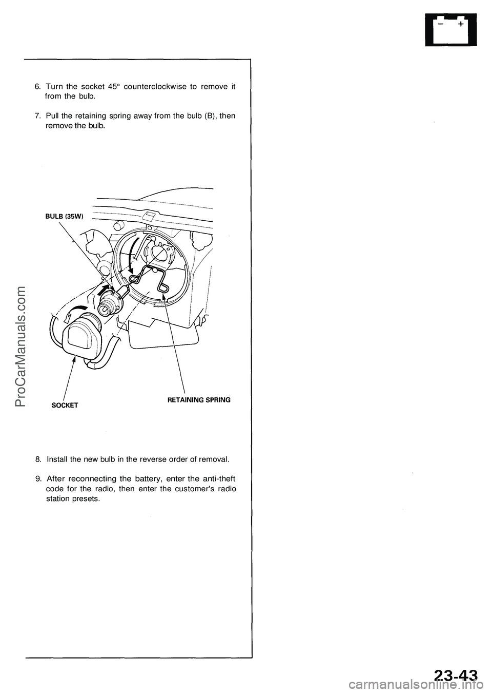
6. Turn the socket 45° counterclockwise to remove it
from the bulb.
7. Pull the retaining spring away from the bulb (B), then
remove the bulb.
8. Install the new bulb in the reverse order of removal.
9. After reconnecting the battery, enter the anti-theft
code for the radio, then enter the customer's radio
station presets.ProCarManuals.com
Page 565 of 1503
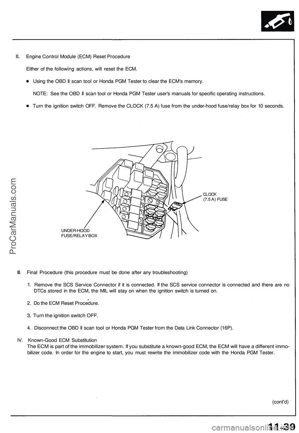
Engine Control Module (ECM) Reset Procedure
Either of the following actions, will reset the ECM.
Using the OBD II scan tool or Honda PGM Tester to clear the ECM's memory.
NOTE: See the OBD II scan tool or Honda PGM Tester user's manuals for specific operating instructions.
Turn the ignition switch OFF. Remove the CLOCK (7.5 A) fuse from the under-hood fuse/relay box for 10 seconds.
UNDER-HOOD
FUSE/RELAY BOX
CLOCK
(7.5 A) FUSE
III. Final Procedure (this procedure must be done after any troubleshooting)
1. Remove the SCS Service Connector if it is connected. If the SCS service connector is connected and there are no
DTCs stored in the ECM, the MIL will stay on when the ignition switch is turned on.
2. Do the ECM Reset Procedure.
3. Turn the ignition switch OFF.
4. Disconnect the OBD II scan tool or Honda PGM Tester from the Data Link Connector (16P).
IV. Known-Good ECM Substitution
The ECM is part of the immobilizer system. If you substitute a known-good ECM, the ECM will have a different immo-
bilizer code. In order for the engine to start, you must rewrite the immobilizer code with the Honda PGM Tester.
(cont'd)ProCarManuals.com
Page 845 of 1503
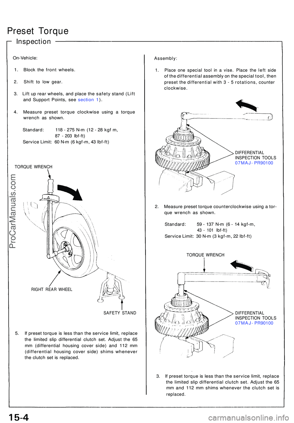
Preset Torqu e
On-Vehicle :
1 . Bloc k th e fron t wheels .
2. Shif t t o lo w gear .
3. Lif t u p rea r wheels , an d plac e th e safet y stan d (Lif t
an d Suppor t Points , se e sectio n 1 ).
4 . Measur e prese t torqu e clockwis e usin g a torqu e
wrenc h a s shown .
Standard : 11 8 - 27 5 N- m (1 2 - 2 8 kg f m ,
87 - 20 3 Ibf-ft )
Servic e Limit : 6 0 N- m (6 kgf-m , 4 3 Ibf-ft )
TORQU E WRENC H
RIGHT REA R WHEE L
SAFETY STAN D
5. I f prese t torqu e i s les s tha n th e servic e limit , replac e
th e limite d sli p differentia l clutc h set . Adjus t th e 6 5
m m (differentia l housin g cove r side ) an d 11 2 m m
(differentia l housin g cove r side ) shim s wheneve r
th e clutc h se t i s replaced .
Assembly :
1. Plac e on e specia l too l i n a vise . Plac e th e lef t sid e
of th e differentia l assembl y o n th e specia l tool , the n
prese t th e differentia l wit h 3 - 5 rotations , counte r
clockwise .
DIFFERENTIA LINSPECTION TOOL S07MAJ - PR9010 0
2. Measur e prese t torqu e counterclockwis e usin g a tor -
qu e wrenc h a s shown .
Standard : 5 9 - 13 7 N- m (6 - 1 4 kgf-m ,
43 - 10 1 Ibf-ft )
Servic e Limit : 3 0 N- m (3 kgf-m , 2 2 Ibf-ft )
TORQU E WRENC H
DIFFERENTIA LINSPECTION TOOL S07MAJ - PR9010 0
3. I f prese t torqu e i s les s tha n th e servic e limit , replac e
th e limite d sli p differentia l clutc h set . Adjus t th e 6 5
m m an d 11 2 m m shim s wheneve r th e clutc h se t i s
replaced .
Inspection
ProCarManuals.com
Page 861 of 1503
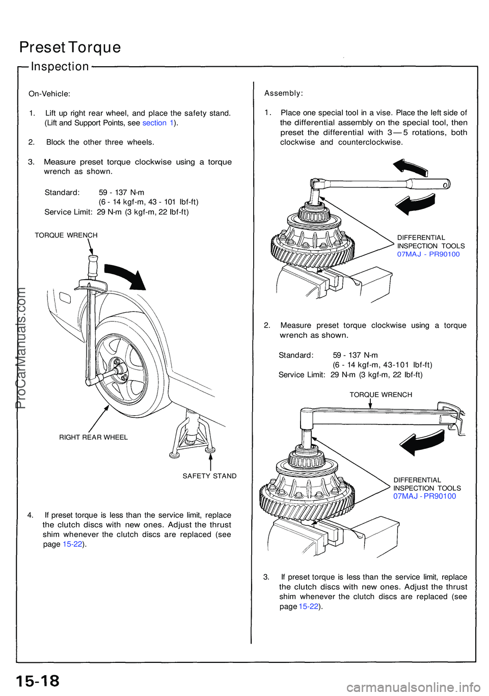
Preset Torqu e
On-Vehicle :
1 . Lif t u p righ t rea r wheel , an d plac e th e safet y stand .
(Lif t an d Suppor t Points , se e sectio n 1 ).
2 . Bloc k th e othe r thre e wheels .
3. Measur e prese t torqu e clockwis e usin g a torqu e
wrenc h a s shown .
Standard : 5 9 - 13 7 N- m
( 6 - 1 4 kgf-m , 4 3 - 10 1 Ibf-ft )
Servic e Limit : 2 9 N- m (3 kgf-m , 2 2 Ibf-ft )
TORQU E WRENC H
RIGH T REA R WHEE L
SAFETY STAN D
4. I f prese t torqu e i s les s tha n th e servic e limit , replac e
the clutc h disc s wit h ne w ones . Adjus t th e thrus t
shim wheneve r th e clutc h disc s ar e replace d (se e
pag e 15-22 ).
Assembly :
Place on e specia l too l i n a vise . Plac e th e lef t sid e o f
the differentia l assembl y o n th e specia l tool , the n
prese t th e differentia l wit h 3 — 5 rotations , bot h
clockwis e an d counterclockwise .
DIFFERENTIALINSPECTION TOOL S07MAJ - PR9010 0
2. Measur e prese t torqu e clockwis e usin g a torqu e
wrench a s shown .
Standard : 5 9 - 13 7 N- m
( 6 - 1 4 kgf-m , 43-10 1 Ibf-ft )
Servic e Limit : 2 9 N- m (3 kgf-m , 2 2 Ibf-ft )
TORQU E WRENC H
DIFFERENTIA LINSPECTION TOOL S07MAJ - PR9010 0
3 . I f prese t torqu e i s les s tha n th e servic e limit , replac e
the clutc h disc s wit h ne w ones . Adjus t th e thrus t
shim wheneve r th e clutc h disc s ar e replace d (se e
pag e 15-22 ).
Inspectio n
ProCarManuals.com
Page 909 of 1503
Troubleshooting Precautions
EPS Indicator Light
Under normal conditions, the EPS indicator light in the gauge assembly comes on when the ignition switch is turned to
the ON (II) position, then goes off after the engine is started. This indicates that the bulb and its circuits are operating cor-
rectly. If there is any trouble in the system, the EPS indicator light turns on during driving, and the power steering assist is
turned off. When the EPS indicator light comes on, the control unit memorizes the DTC. In this case, the control unit does
not activate the EPS system after the engine starts again but it keeps the EPS indicator light on.
Diagnostic Trouble Code (DTC)
• The lowest DTC is indicated first.
• The DTCs continue blinking until the ignition switch is turned off.
• The DTCs are erased from the control unit when the EPS control unit VBU power supply or connector is disconnected.
• The EPS system can be reset and the control unit's memory can be erased by disconnecting the CLOCK (7.5 A) fuse for
more than ten seconds.
Self-diagnosis:
The CPU (central processing unit) controls the following when it detects a problem during self-diagnosis:
1. Turns the EPS indicator light ON to alert the driver.
2. Power assist stops, and normal manual steering operation resumes (except DTC 33).
3. The EPS control unit memorizes the diagnostic trouble code (DTC).
4. After the DTC is stored in the control unit, the CPU stops self-diagnosis.
Troubleshooting:
• Before starting the troubleshooting, clear the DTC by disconnecting the CLOCK (7.5 A) fuse for ten seconds or more,
and test-drive the car. Check that the symptom of the trouble appears again, and then troubleshoot.
• When both EPS indicator light and A/T "D" indicator light come on, perform the A/T troubleshooting first.
• When the customer's reported problem cannot be verified in the car, ask the customer about the conditions when the
EPS indicator light came ON, then test-drive the car under those conditions, if possible. If the EPS indicator light does
not come ON during the test, check for loose connections or poor contacts at the connectors by wiggling the harness,
etc.
• The connector terminal numbers are viewed from the wire side for the female terminals and from the terminal side for
the male terminals.
• After the repair, test-drive the car and check that the EPS indicator light does not come ON again during the test. (Refer
to the Symptom-to-System Chart for diagnostic period.)ProCarManuals.com