Page 252 of 1503
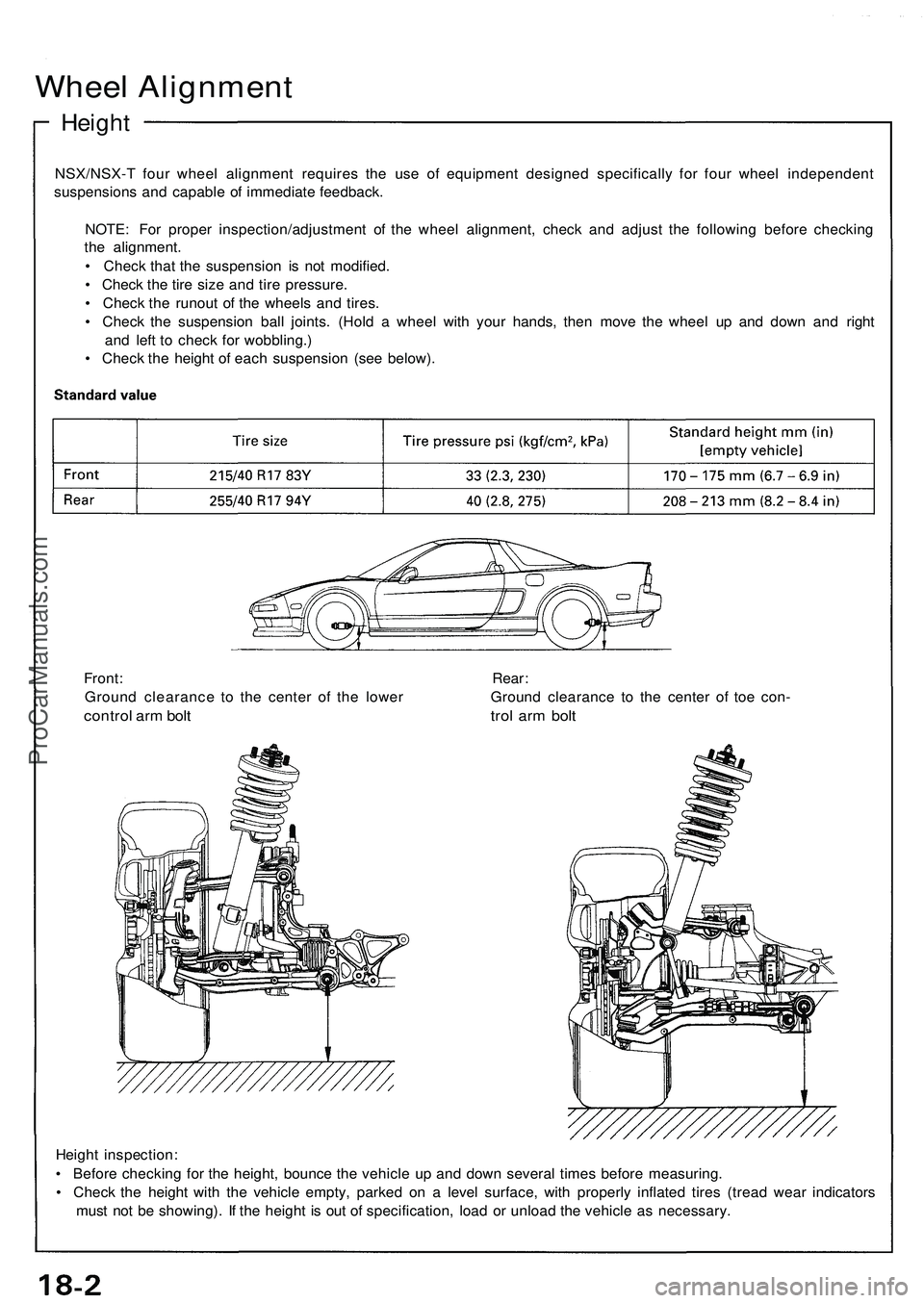
Wheel Alignment
Height
NSX/NSX- T fou r whee l alignmen t require s th e us e o f equipmen t designe d specificall y fo r fou r whee l independen t
suspension s an d capabl e o f immediat e feedback .
NOTE : Fo r prope r inspection/adjustmen t o f th e whee l alignment , chec k an d adjus t th e followin g befor e checkin g
th e alignment .
• Chec k tha t th e suspensio n i s no t modified .
• Chec k th e tir e siz e an d tir e pressure .
• Chec k th e runou t o f th e wheel s an d tires .
• Chec k th e suspensio n bal l joints . (Hol d a whee l wit h you r hands , the n mov e th e whee l u p an d dow n an d righ t
an d lef t t o chec k fo r wobbling. )
• Chec k th e heigh t o f eac h suspensio n (se e below) .
Heigh t inspection :
• Befor e checkin g fo r th e height , bounc e th e vehicl e u p an d dow n severa l time s befor e measuring .
• Chec k th e heigh t wit h th e vehicl e empty , parke d o n a leve l surface , wit h properl y inflate d tire s (trea d wea r indicator s
mus t no t b e showing) . I f th e heigh t i s ou t o f specification , loa d o r unloa d th e vehicl e a s necessary .
Front
: Rear :
Groun d clearanc e t o th e cente r o f th e lowe r Groun d clearanc e t o th e cente r o f toe con -
contro l ar m bol t tro l ar m bol t
ProCarManuals.com
Page 370 of 1503
3-15
T
ITEMMETRICENGLISH
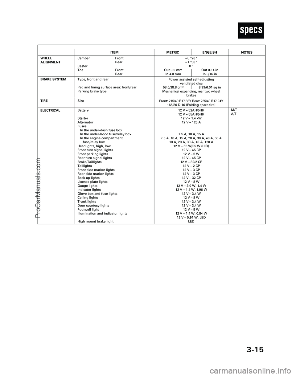
ELECTRICALBattery
Starter
Alternator
Fuses
In the under-dash fuse box
In the under-hood fuse/relay box
In the engine compartment
fuse/relay box
Headlights, high, low
Front turn signal lights
Front parking lights
Rear turn signal lights
Brake/Taillights
Taillights
Front side marker lights
Rear side marker lights
Back-up lights
License plate lights
Gauge lights
Indicator lights
Glove box and fuse lights
Ceiling lights
Trunk lights
Door courtesy lights
Footwell light
Illumination and indicator lights
High mount brake light12 V – 52AH/5HR
12 V – 55AH/5HR
12 V – 1.4 kW
12 V – 120 A
7.5 A, 10 A, 15 A
7.5 A, 10 A, 15 A, 20 A, 30 A, 40 A, 50 A
10 A, 20 A, 30 A, 40 A, 120 A
12 V – 65 W/35 W (HID)
12 V – 45 CP
12 V – 5 W
12 V – 45 CP
12 V – 32/2 CP
12 V – 2 CP
12 V – 3 CP
12 V – 3 CP
12 V – 32 CP
12 V – 8 W
12 V – 3.0 W, 1.4 W
12 V – 1.4 W, 1.96 W
12 V – 3.4 W
12 V – 8 W
12 V – 3.4 W
12 V – 3.4 W
12 V – 5 W
12 V – 1.4 W, 0.84 W
12 V – 0.91 W, LED
LED
TIRE
M/T
A/T
BRAKE SYSTEM
Front: 215/40 R17 83Y Rear: 255/40 R17 94Y165/80 D 16 (Folding spare tire)
Power assisted self-adjusting
ventilated disc
58.0/38.8 cm
28.99/6.01 sq in
Mechanical expanding, rear two wheel
brakes
WHEEL
ALIGNMENTCamber Front
Rear
Caster
Toe Front
Rear–0 °20 ’
–1 °30 ’
8 °
Out 3.5 mm Out 0.14 in
In 4.0 mm In 3/16 in
NOTES
Size
Type, front and rear
Pad and lining surface area: front/rear
Parking brake type
*04-NSX (61SW004)SEC03(01-16) 9/22/04 1:49 PM Page 3-15
ProCarManuals.com
Page 939 of 1503
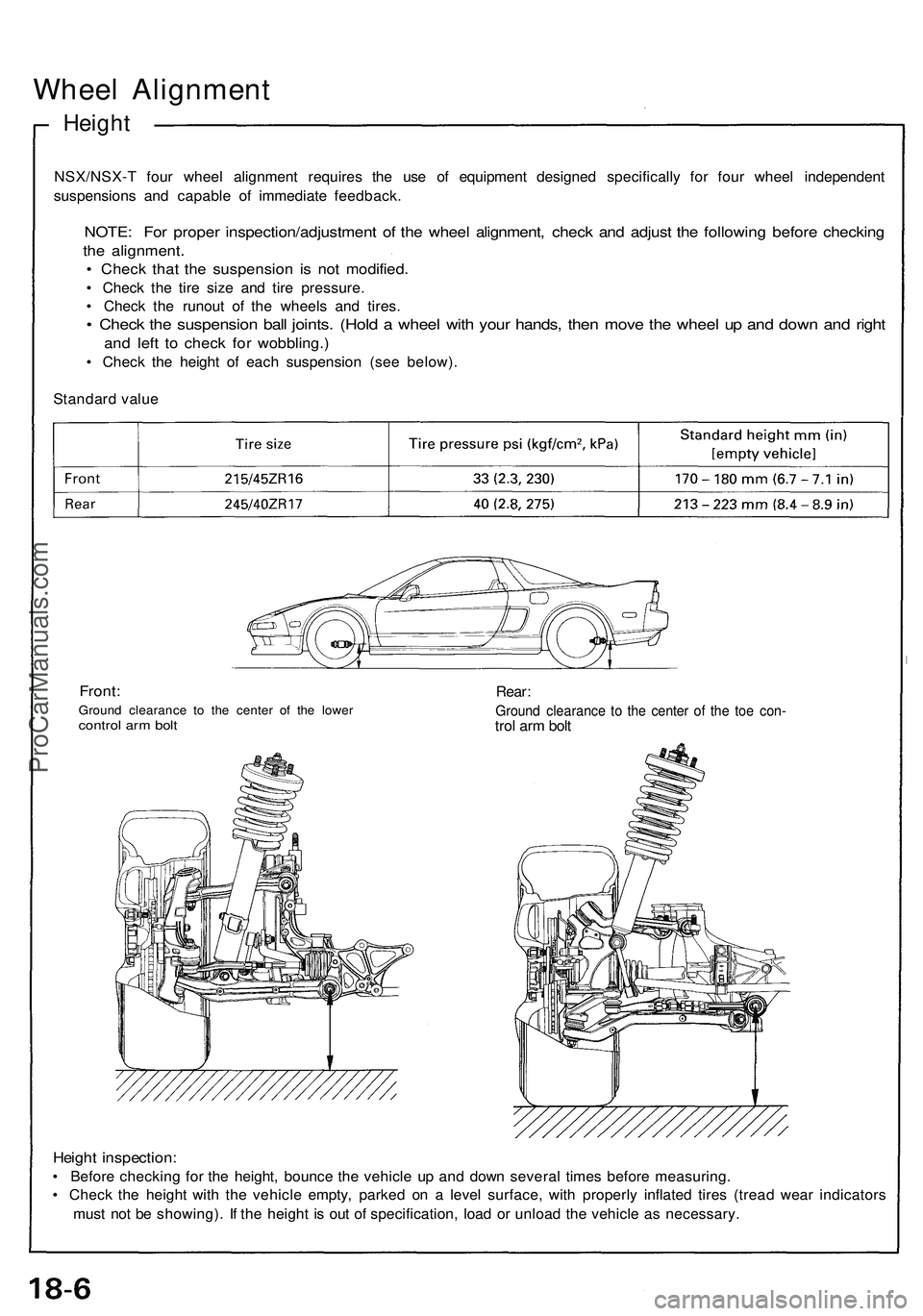
Wheel Alignment
Height
NSX/NSX-T four wheel alignment requires the use of equipment designed specifically for four wheel independent
suspensions and capable of immediate feedback.
NOTE: For proper inspection/adjustment of the wheel alignment, check and adjust the following before checking
the alignment.
• Check that the suspension is not modified.
• Check the tire size and tire pressure.
• Check the runout of the wheels and tires.
• Check the suspension ball joints. (Hold a wheel with your hands, then move the wheel up and down and right
and left to check for wobbling.)
• Check the height of each suspension (see below).
Standard value
Front:
Ground clearance to the center of the lower
control arm bolt
Rear:
Ground clearance to the center of the toe con-
trol arm bolt
Height inspection:
• Before checking for the height, bounce the vehicle up and down several times before measuring.
• Check the height with the vehicle empty, parked on a level surface, with properly inflated tires (tread wear indicators
must not be showing). If the height is out of specification, load or unload the vehicle as necessary.ProCarManuals.com
Page 940 of 1503
Front Wheel Alignment Adjusting Procedure
Adjustment
NOTE: NSX/NSX-T four wheel alignment requires the use of equipment designed specifically for four wheel independent
suspensions and capable of immediate feedback.
The NSX/NSX-T suspension can be adjusted for camber, caster (front only), and toe. However, because each of them
relates to the other, the camber changes when the toe is adjusted for example. Therefore, the total adjustment of the
front/rear wheel alignment is required whenever one of the elements (camber, caster, or toe) is adjusted.
Front wheel alignment adjusting procedure
Measure and adjust both camber and toe of the
left side.
Measure and adjust both camber and toe of the
right side.
Adjust caster on both sides.
Measure and readjust both camber and toe of
the left side.
Measure and readjust both camber and toe of
the right side.
TOP VIEW:
CASTER
TOE
CAMBER
Check tire pressure on both sides.
Check the ride height on both sides.ProCarManuals.com
Page 944 of 1503
Rear Wheel Alignment Adjusting Procedure
Rear wheel alignment adjusting procedure
Check tire pressure on both sides.
Check the ride height on both sides.
Adjust both camber and toe of the left side.
Adjust both camber and toe of the right side.
TOP VIEW:
CAMBER
TOEProCarManuals.com
Page 1477 of 1503
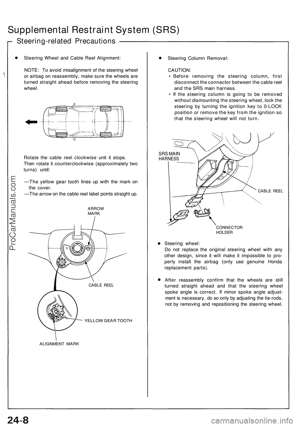
Supplemental Restraint System (SRS)
Steering-related Precautions
Steering Wheel and Cable Reel Alignment:
NOTE: To avoid misalignment of the steering wheel
or airbag on reassembly, make sure the wheels are
turned straight ahead before removing the steering
wheel.
Rotate the cable reel clockwise unit it stops.
Then rotate it counterclockwise (approximately two
turns) until:
—The yellow gear tooth lines up with the mark on
the cover.
—The arrow on the cable reel label points straight up.
ARROW
MARK
YELLOW GEAR TOOTH
ALIGNMENT MARK
Steering Column Removal:
CAUTION:
• Before removing the steering column, first
disconnect the connector between the cable reel
and the SRS main harness.
• If the steering column is going to be removed
without dismounting the steering wheel, lock the
steering by turning the ignition key to 0-LOCK
position or remove the key from the ignition so
that the steering wheel will not turn.
SRS MAIN
HARNESS
CABLE REEL
CONNECTOR
HOLDER
Steering wheel:
Do not replace the original steering wheel with any
other design, since it will make it impossible to pro-
perly install the airbag (only use genuine Honda
replacement parts).
After reassembly confirm that the wheels are still
turned straight ahead and that the steering wheel
spoke angle is correct. If minor spoke angle adjust-
ment is necessary, do so only by adjusting the tie-rods,
not by removing and repositioning the steering wheel.
CABLE REELProCarManuals.com
Page 1495 of 1503
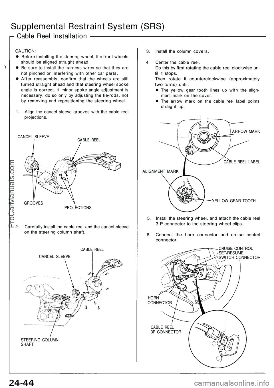
Supplemental Restraint System (SRS)
Cable Reel Installation
CAUTION:
Before installing the steering wheel, the front wheels
should be aligned straight ahead.
Be sure to install the harness wires so that they are
not pinched or interfering with other car parts.
After reassembly, confirm that the wheels are still
turned straight ahead and that steering wheel spoke
angle is correct. If minor spoke angle adjustment is
necessary, do so only by adjusting the tie-rods, not
by removing and repositioning the steering wheel.
1. Align the cancel sleeve grooves with the cable reel
projections.
CANCEL SLEEVE
CABLE REEL
GROOVES
PROJECTIONS
2. Carefully install the cable reel and the cancel sleeve
on the steering column shaft.
CABLE REEL
CANCEL SLEEVE
STEERING COLUMN
SHAFT
3. Install the column covers.
4. Center the cable reel.
Do this by first rotating the cable reel clockwise un-
til it stops.
Then rotate it counterclockwise (approximately
two turns) until:
The yellow gear tooth lines up with the align-
ment mark on the cover.
The arrow mark on the cable reel label points
straight up.
ARROW MARK
CABLE REEL LABEL
ALIGNMENT MARK
YELLOW GEAR TOOTH
5. Install the steering wheel, and attach the cable reel
3-P connector to the steering wheel clips.
6. Connect the horn connector and cruise control
connector.
CRUISE CONTROL
SET/RESUME
SWITCH CONNECTOR
HORN
CONNECTOR
CABLE REEL
3P CONNECTORProCarManuals.com