1997 ACURA NSX fuel cap
[x] Cancel search: fuel capPage 140 of 1503
Emission Control System
Evaporative Emission (EVAP) Controls
Description
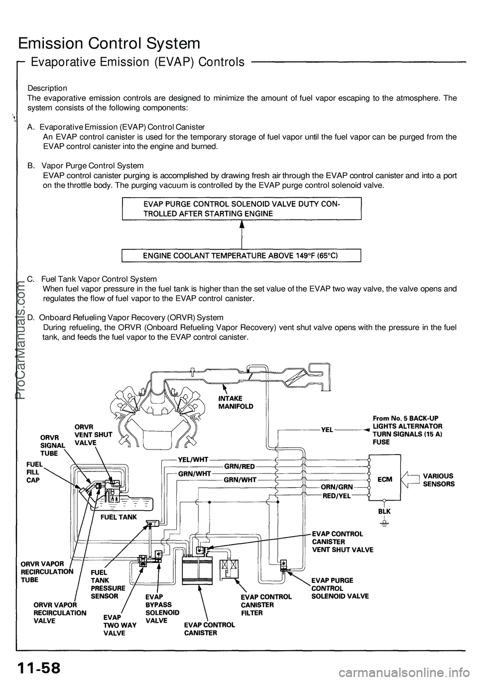
The evaporative emission controls are designed to minimize the amount of fuel vapor escaping to the atmosphere. The
system consists of the following components:
A. Evaporative Emission (EVAP) Control Canister
An EVAP control canister is used for the temporary storage of fuel vapor until the fuel vapor can be purged from the
EVAP control canister into the engine and burned.
B. Vapor Purge Control System
EVAP control canister purging is accomplished by drawing fresh air through the EVAP control canister and into a port
on the throttle body. The purging vacuum is controlled by the EVAP purge control solenoid valve.
C. Fuel Tank Vapor Control System
When fuel vapor pressure in the fuel tank is higher than the set value of the EVAP two way valve, the valve opens and
regulates the flow of fuel vapor to the EVAP control canister.
D. Onboard Refueling Vapor Recovery (ORVR) System
During refueling, the ORVR (Onboard Refueling Vapor Recovery) vent shut valve opens with the pressure in the fuel
tank, and feeds the fuel vapor to the EVAP control canister.ProCarManuals.com
Page 368 of 1503
3-13
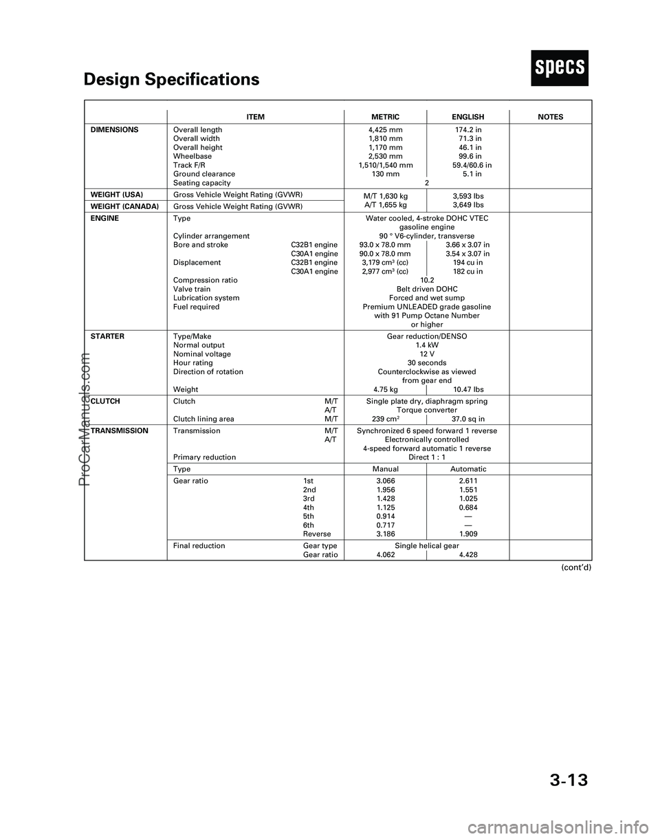
TDesign Specifications
(cont’d)
ITEMMETRICENGLISH
DIMENSIONSOverall length
Overall width
Overall height
Wheelbase
Track F/R
Ground clearance
Seating capacity4,425 mm 174.2 in
1,810 mm 71.3 in
1,170 mm 46.1 in
2,530 mm 99.6 in
1,510/1,540 mm 59.4/60.6 in
130 mm 5.1 in
2
WEIGHT (USA)
Single plate dry, diaphragm spring
Torque converter
239 cm
237.0 sq in
CLUTCHClutch M/T
A/T
Clutch lining area M/T
Gross Vehicle Weight Rating (GVWR)
NOTES
Gear reduction/DENSO
1.4 kW
12 V
30 seconds
Counterclockwise as viewed
from gear end
4.75 kg 10.47 lbs
ENGINEWater cooled, 4-stroke DOHC VTEC
gasoline engine
90 °V6-cylinder, transverse
93.0 x 78.0 mm 3.66 x 3.07 in
90.0 x 78.0 mm 3.54 x 3.07 in
3,179 cm
3(cc) 194 cu in
2,977 cm3(cc) 182 cu in
10.2
Belt driven DOHC
Forced and wet sump
Premium UNLEADED grade gasoline
with 91 Pump Octane Number
or higher
STARTERType/Make
Normal output
Nominal voltage
Hour rating
Direction of rotation
Weight
WEIGHT (CANADA)Gross Vehicle Weight Rating (GVWR)
Synchronized 6 speed forward 1 reverse
Electronically controlled
4-speed forward automatic 1 reverse
Direct 1 : 1Transmission M/T
A/T
Primary reduction
Manual AutomaticType
3.066 2.611
1.956 1.551
1.428 1.025
1.125 0.684
0.914—
0.717—
3.186 1.909Gear ratio 1st
2nd
3rd
4th
5th
6th
Reverse
Single helical gear
4.062 4.428
TRANSMISSION
Final reduction Gear type
Gear ratio
Type
Cylinder arrangement
Bore and strokeC32B1 engine
C30A1 engine
DisplacementC32B1 engine
C30A1 engine
Compression ratio
Valve train
Lubrication system
Fuel required
M/T 1,630 kg 3,593 lbs
A/T 1,655 kg 3,649 lbs
*04-NSX (61SW004)SEC03(01-16) 9/22/04 1:49 PM Page 3-13
ProCarManuals.com
Page 374 of 1503

4-5
Y
Do the items in parts A, B, C, D, E, F, and G as required for the mileag\
e/time interval listed.
NOTE: According to state and federal regulations, failure to do the maintenanc\
e items marked with an asterisk (*) will not
void the customer ’s emissions warranties. However, Acura recommends that all maintenance s\
ervices be done at
the recommended interval to ensure long-term reliability.
*1: Refer to the 1997 NSX Service Manual, P/N 61SL006.
*2: Refer to the 1998 NSX Service Manual Supplement, P/N 61SL007.
*3: Refer to the 2001 NSX Service Manual Supplement, P/N 61SW000.
A
B Replace engine oil (see page
8-2)*
2, every 7,500 miles (12,000 km) or 1 year.
Engine oil capacity: without oil filter: 4.3 L (4.5 US qt).
Check tire inflation and condition at least once a month, every 7,500 mi\
les (12,000 km).
Replace engine oil filter (see page 8-5)*1, every 15,000 miles (24,000 km) or 1 year.
Engine oil capacity: with oil filter: 5.0 L (5.3 US qt).
Check front and rear brake wear (see page 19-4)*1, every 15,000 miles (24,000 km) or 1 year.
• Check pads and discs for wear (thickness), damage, and cracks.
• Check calipers for damage, leaks, and tightness of mounting bolts.
Check parking brake adjustment (see page 19-5)*1, every 15,000 miles (24,000 km) or 1 year.
Check the number of clicks (10 to 14) when the parking brake lever is pulled with 196 N (20 kgf,\
44 lbf) of force.
Inspect tie-rod ends, steering gearbox, and gearbox boots (see page 17-57)*1, every 15,000 miles (24,000 km) or 1 year.
• Check rack grease and steering linkage.
• Check boots for damage and leaking grease.
• Check fluid lines for damage and leaks.1
• Check bolts for tightness.
• Check condition of ball joint boots for deterioration and damage.
Inspect driveshaft boots (see page 16-3)*1, every 15,000 miles (24,000 km) or 1 year.
Check boots for cracks and boot bands for tightness.
Inspect brake hoses and lines including ABS (see page 19-27)*1, every 15,000 miles (24,000 km) or 1 year.
Check the master cylinder, proportioning control valve and ABS modulator\
for damage and leakage.
Inspect all fluid levels and condition of fluids, every 15,000 miles (2\
4,000 km) or 1 year.
• Manual transmission fluid (MTF) (see page 13-3)*
1.
• Automatic transmission fluid (ATF-Z1) (see page 14-105)*1.
• Engine coolant (see page 10-2)*1.
• Brake fluid (see page 19-84)*1.
• Windshield washer fluid.
Cooling system hoses and connections (see page 10-2)*1, every 15,000 miles (24,000 km) or 1 year.
• Check all hoses for damage, leaks and deterioration.
• Check for proper fan operation.
Inspect exhaust system (see page 9-6)*, *1, every 15,000 miles (24,000 km) or 1 year.
Check catalytic converter heat shield, exhaust pipe, and muffler for dam\
age, leaks, and tightness ( see page 9-14 ).
Inspect fuel lines and connections (see page 11-130)*, *1, every 15,000 miles (24,000 km) or 1 year.
Check for loose connections, cracks, and deterioration; retighten loose \
connections and replace damaged parts.
Part Maintenance Items
*05-NSX (61SW004)SEC04(01-10) 9/22/04 1:49 PM Page 4-5
Inspect suspension components (see page 18-14)* , every 15,000 miles (24,000 km) or 1 year.
ProCarManuals.com
Page 375 of 1503
4-6
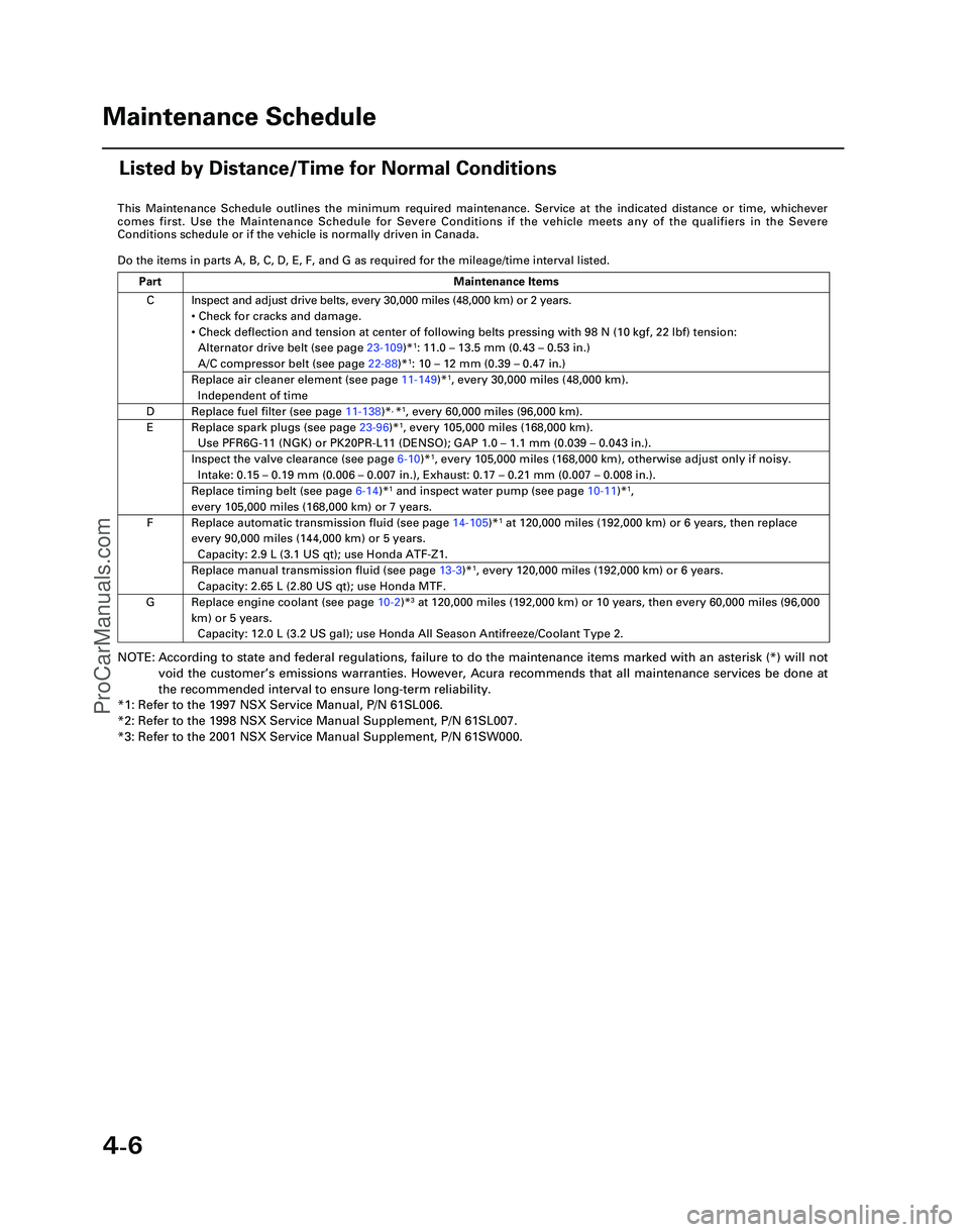
This Maintenance Schedule outlines the minimum required maintenance. Ser\
vice at the indicated distance or time, whichever
comes first. Use the Maintenance Schedule for Severe Conditions if the v\
ehicle meets any of the qualifiers in the Severe
Conditions schedule or if the vehicle is normally driven in Canada.
Do the items in parts A, B, C, D, E, F, and G as required for the mileag\
e/time interval listed.
NOTE: According to state and federal regulations, failure to do the maintenanc\
e items marked with an asterisk (*) will not
void the customer ’s emissions warranties. However, Acura recommends that all maintenance s\
ervices be done at
the recommended interval to ensure long-term reliability.
*1: Refer to the 1997 NSX Service Manual, P/N 61SL006.
*2: Refer to the 1998 NSX Service Manual Supplement, P/N 61SL007.
*3: Refer to the 2001 NSX Service Manual Supplement, P/N 61SW000.
C
D
E
F
G Inspect and adjust drive belts, every 30,000 miles (48,000 km) or 2 ye\
ars.
•
Check for cracks and damage.
• Check deflection and tension at center of following belts pressing with\
98 N (10 kgf, 22 lbf) tension:
Alternator drive belt (see page 23-109)*
1: 11.0 – 13.5 mm (0.43 – 0.53 in.)
A/C compressor belt (see page 22-88)*1: 10 – 12 mm (0.39 – 0.47 in.)
Replace air cleaner element (see page 11-149)*1, every 30,000 miles (48,000 km).
Independent of time
Replace fuel filter (see page 11-138)*, *1, every 60,000 miles (96,000 km).
Replace spark plugs (see page 23-96)*1, every 105,000 miles (168,000 km).
Use PFR6G-11 (NGK) or PK20PR-L11 (DENSO); GAP 1.0 – 1.1 mm (0.039 – 0.043 in.).
Inspect the valve clearance (see page 6-10)*1, every 105,000 miles (168,000 km), otherwise adjust only if noisy.
Intake: 0.15 – 0.19 mm (0.006 – 0.007 in.), Exhaust: 0.17 – 0.21 mm (0.007 – 0.008 in.).
Replace timing belt (see page 6-14)*1 and inspect water pump (see page 10-11)*1,
every 105,000 miles (168,000 km) or 7 years.
Replace automatic transmission fluid (see page 14-105)*1 at 120,000 miles (192,000 km) or 6 years, then replace
every 90,000 miles (144,000 km) or 5 years.
Capacity: 2.9 L (3.1 US qt); use Honda ATF-Z1.
Replace manual transmission fluid (see page 13-3)*1, every 120,000 miles (192,000 km) or 6 years.
Capacity: 2.65 L (2.80 US qt); use Honda MTF.
Replace engine coolant (see page 10-2 )*3 at 120,000 miles (192,000 km) or 10 years, then every 60,000 miles (9\
6,000
km) or 5 years. Capacity: 12.0 L (3.2 US gal); use Honda All Season Antifreeze/Coolant\
Type 2.
Part Maintenance Items
Maintenance Schedule
Listed by Distance/Time for Normal Conditions
*05-NSX (61SW004)SEC04(01-10) 9/22/04 1:49 PM Page 4-6
ProCarManuals.com
Page 608 of 1503
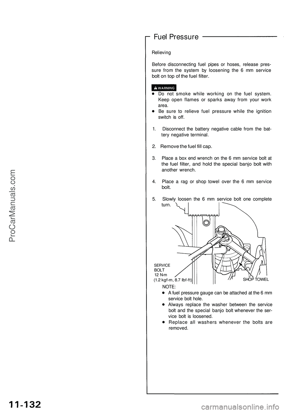
Fuel Pressur e
Relieving
Before disconnectin g fue l pipe s o r hoses , releas e pres -
sur e fro m th e syste m b y loosenin g th e 6 m m servic e
bolt o n to p o f th e fue l filter .
Do no t smok e whil e workin g o n th e fue l system .
Kee p ope n flame s o r spark s awa y fro m you r wor k
area.
Be sur e t o reliev e fue l pressur e whil e th e ignitio n
switc h i s off .
1 . Disconnec t th e batter y negativ e cabl e fro m th e bat -
ter y negativ e terminal .
2. Remov e th e fue l fil l cap .
3. Plac e a bo x en d wrenc h o n th e 6 m m servic e bol t a t
the fue l filter , an d hol d th e specia l banj o bol t wit h
anothe r wrench .
4 . Plac e a ra g o r sho p towe l ove r th e 6 m m servic e
bolt.
5. Slowl y loose n th e 6 m m servic e bol t on e complet e
turn .
SHO P TOWE L
SERVIC EBOLT12 N- m(1.2 kgf-m , 8. 7 Ibf-ft )
NOTE :
A fue l pressur e gaug e ca n b e attache d a t th e 6 m m
servic e bol t hole .
Alway s replac e th e washe r betwee n th e servic e
bol t an d th e specia l banj o bol t wheneve r th e ser -
vic e bol t i s loosened .
Replac e al l washer s wheneve r th e bolt s ar e
removed .
ProCarManuals.com
Page 636 of 1503
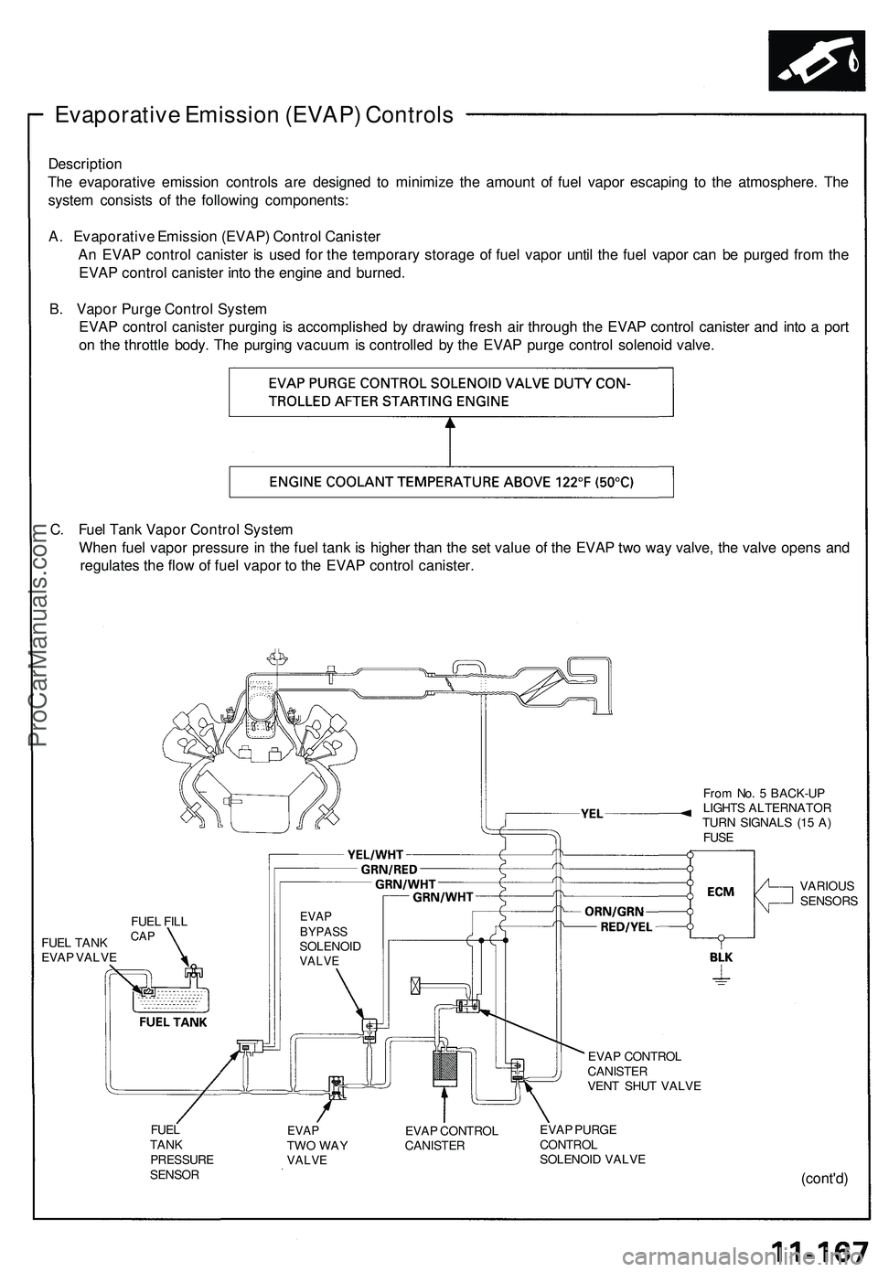
Evaporative Emission (EVAP) Controls
Description
The evaporative emission controls are designed to minimize the amount of fuel vapor escaping to the atmosphere. The
system consists of the following components:
A. Evaporative Emission (EVAP) Control Canister
An EVAP control canister is used for the temporary storage of fuel vapor until the fuel vapor can be purged from the
EVAP control canister into the engine and burned.
B. Vapor Purge Control System
EVAP control canister purging is accomplished by drawing fresh air through the EVAP control canister and into a port
on the throttle body. The purging vacuum is controlled by the EVAP purge control solenoid valve.
C. Fuel Tank Vapor Control System
When fuel vapor pressure in the fuel tank is higher than the set value of the EVAP two way valve, the valve opens and
regulates the flow of fuel vapor to the EVAP control canister.
From No. 5 BACK-UP
LIGHTS ALTERNATOR
TURN SIGNALS (15 A)
FUSE
FUEL TANK
EVAP VALVE
EVAP
BYPASS
SOLENOID
VALVE
VARIOUS
SENSORS
EVAP CONTROL
CANISTER
VENT SHUT VALVE
FUEL
TANK
PRESSURE
SENSOR
EVAP
TWO WAY
VALVE
EVAP CONTROL
CANISTER
EVAP PURGE
CONTROL
SOLENOID VALVE
(cont'd)
FUEL FILL
CAPProCarManuals.com