1997 ACURA NSX turn signal
[x] Cancel search: turn signalPage 100 of 1503

Electrical Connection s
FUSES
BRAK E LIGHT S HOR N (20A )
TH L MOTO R (20A)* *
CLOC K (7.5A) *
AC G (120A)* *
ACG(S ) (20A)* *
I G COI L (30A)* *
No . 2 FUE L PUM P SRS 2 (15A )
No . 5 BACK-U P LIGHT S
ALTERNATO R
TURN SIGNAL S (15A )
STARTE R SIGNA L (7.5A)** *
AI R PUM P (60A)* * I
n th e under-hoo d fuse/rela y bo x
I n th e engin e compartmen t fuse/rela y bo x
I n th e under-das h fus e bo x
System Description
ProCarManuals.com
Page 141 of 1503

Pulsed Secondary Air Injection System Description
The air pump system is designed to advance the activation of the catalyst and to reduce the hydrocarbons (HC), carbon
monoxide (CO), and oxides of nitrogen (NOx) in the exhaust gas.
The system operates after the engine starts under the following conditions:
• The engine coolant temperature is between 0°C and 70°C (32°F and 158°F).
• The difference in engine coolant temperature is more than 20°C (36°F) between the time when the engine is started and
when the engine is stopped in the previous driving cycle.
AIR CONTROL
SOLENOID VALVE
AIR CONTROL
VALVE
WHT
AIR PUMP
RELAY
From
No. 5 BACK-UP LIGHTS
ALTERNATOR
TURN SIGNALS
(15 A) FUSE
From
AIR PUMP
(60 A) FUSE
AIR CONTROL VALVE
VACUUM TANK
AIR CONTROL VALVE
CHECK VALVE
When the engine is started, the air pump runs and sends fresh air to the air control valve. The air control valve allows the
fresh air to flow to the exhaust ports when its diaphragm is pulled by engine vacuum. It gets engine vacuum from the air
control solenoid, which is activated by the ECM. Once the fresh air flows into the exhaust ports near the exhaust valves, it
reacts with the exhaust gases, raising exhaust gas temperatures. This promotes faster warm-up of the catalytic converter.
The system operates for a maximum of 60 seconds, but the running time shortens in relation to the engine coolant tem-
perature and the intake air temperature. When the system is not operating, the air control solenoid and the air control
valve are closed to prevent exhaust gases from entering the system.
AIR PUMP
ELECTRICAL
CURRENT
SENSORProCarManuals.com
Page 276 of 1503
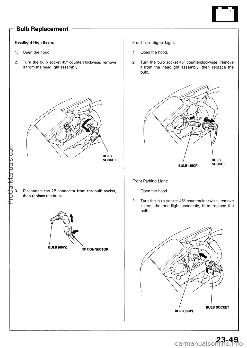
Front Turn Signal Light:
1. Open the hood.
2. Turn the bulb socket 45° counterclockwise, remove
it from the headlight assembly, then replace the
bulb.
Front Parking Light:
1. Open the hood.
2. Turn the bulb socket 45° counterclockwise, remove
it from the headlight assembly, then replace the
bulb.ProCarManuals.com
Page 370 of 1503
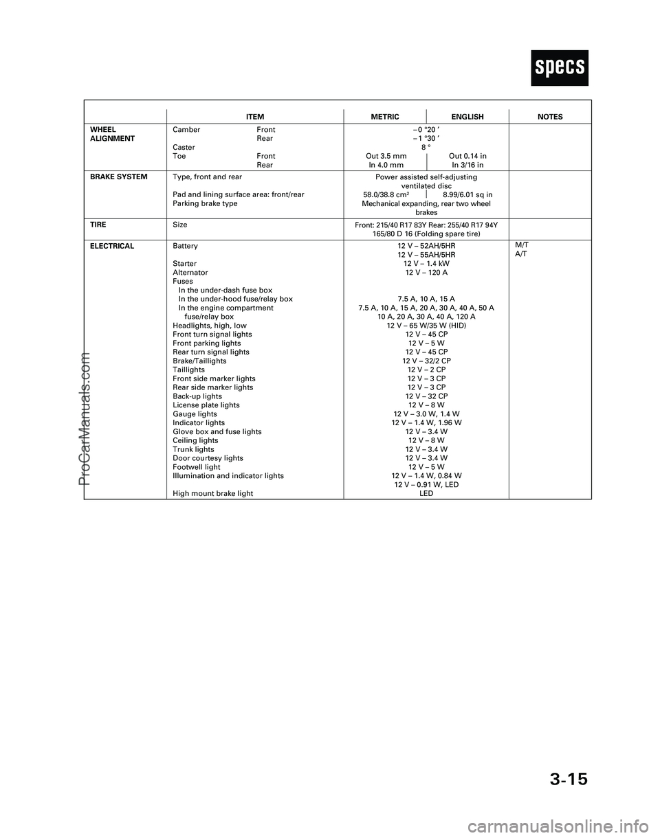
3-15
T
ITEMMETRICENGLISH
ELECTRICALBattery
Starter
Alternator
Fuses
In the under-dash fuse box
In the under-hood fuse/relay box
In the engine compartment
fuse/relay box
Headlights, high, low
Front turn signal lights
Front parking lights
Rear turn signal lights
Brake/Taillights
Taillights
Front side marker lights
Rear side marker lights
Back-up lights
License plate lights
Gauge lights
Indicator lights
Glove box and fuse lights
Ceiling lights
Trunk lights
Door courtesy lights
Footwell light
Illumination and indicator lights
High mount brake light12 V – 52AH/5HR
12 V – 55AH/5HR
12 V – 1.4 kW
12 V – 120 A
7.5 A, 10 A, 15 A
7.5 A, 10 A, 15 A, 20 A, 30 A, 40 A, 50 A
10 A, 20 A, 30 A, 40 A, 120 A
12 V – 65 W/35 W (HID)
12 V – 45 CP
12 V – 5 W
12 V – 45 CP
12 V – 32/2 CP
12 V – 2 CP
12 V – 3 CP
12 V – 3 CP
12 V – 32 CP
12 V – 8 W
12 V – 3.0 W, 1.4 W
12 V – 1.4 W, 1.96 W
12 V – 3.4 W
12 V – 8 W
12 V – 3.4 W
12 V – 3.4 W
12 V – 5 W
12 V – 1.4 W, 0.84 W
12 V – 0.91 W, LED
LED
TIRE
M/T
A/T
BRAKE SYSTEM
Front: 215/40 R17 83Y Rear: 255/40 R17 94Y165/80 D 16 (Folding spare tire)
Power assisted self-adjusting
ventilated disc
58.0/38.8 cm
28.99/6.01 sq in
Mechanical expanding, rear two wheel
brakes
WHEEL
ALIGNMENTCamber Front
Rear
Caster
Toe Front
Rear–0 °20 ’
–1 °30 ’
8 °
Out 3.5 mm Out 0.14 in
In 4.0 mm In 3/16 in
NOTES
Size
Type, front and rear
Pad and lining surface area: front/rear
Parking brake type
*04-NSX (61SW004)SEC03(01-16) 9/22/04 1:49 PM Page 3-15
ProCarManuals.com
Page 536 of 1503
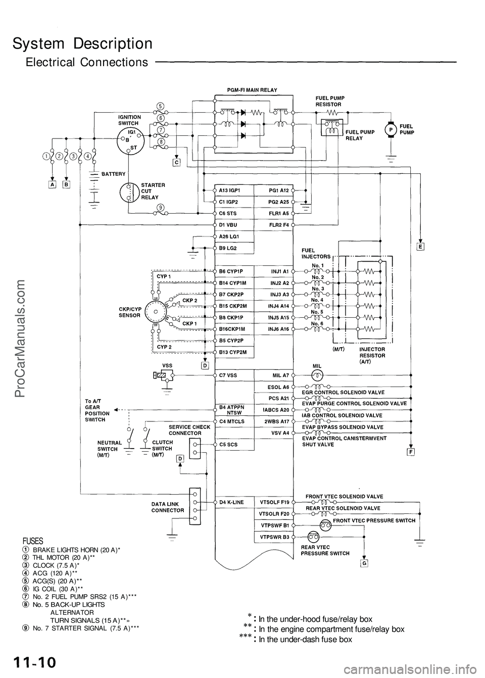
System Descriptio n
Electrical Connection s
In th e under-hoo d fuse/rela y bo x
I n th e engin e compartmen t fuse/rela y bo x
I n th e under-das h fus e bo x
FUSE SBRAK E LIGHT S HOR N (2 0 A) *
TH L MOTO R (2 0 A)* *
CLOC K (7. 5 A) *
AC G (12 0 A)* *ACG(S ) (2 0 A)* *IG COI L (3 0 A)* *
No . 2 FUE L PUM P SRS 2 (1 5 A)** *
No. 5 BACK-U P LIGHT SALTERNATO RTURN SIGNAL S (1 5 A)** »No. 7 STARTE R SIGNA L (7. 5 A)** *
ProCarManuals.com
Page 570 of 1503
Troubleshooting
Troubleshooting Procedures (cont'd)
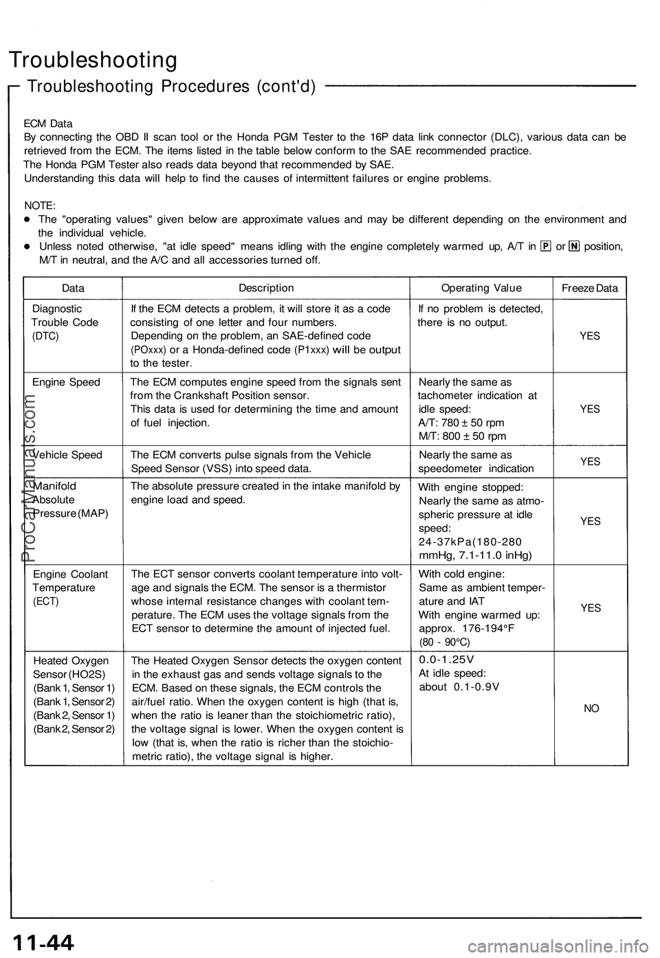
ECM Data
By connecting the OBD II scan tool or the Honda PGM Tester to the 16P data link connector (DLC), various data can be
retrieved from the ECM. The items listed in the table below conform to the SAE recommended practice.
The Honda PGM Tester also reads data beyond that recommended by SAE.
Understanding this data will help to find the causes of intermittent failures or engine problems.
NOTE:
The "operating values" given below are approximate values and may be different depending on the environment and
the individual vehicle.
Unless noted otherwise, "at idle speed" means idling with the engine completely warmed up, A/T in or position,
M/T in neutral, and the A/C and all accessories turned off.
Data
Description
Operating Value
Freeze Data
Diagnostic
Trouble Code
(DTC)
If the ECM detects a problem, it will store it as a code
consisting of one letter and four numbers.
Depending on the problem, an SAE-defined code
(POxxx)
or a
Honda-defined code
(P1xxx)
will
be
output
to the tester.
If no problem is detected,
there is no output.
YES
Engine Speed
The ECM computes engine speed from the signals sent
from the Crankshaft Position sensor.
This data is used for determining the time and amount
of fuel injection.
Nearly the same as
tachometer indication at
idle speed:
A/T:
780 ± 50 rpm
M/T:
800 ± 50 rpm
YES
Vehicle Speed
The ECM converts pulse signals from the Vehicle
Speed Sensor (VSS) into speed data.
Nearly the same as
speedometer indication
YES
Manifold
Absolute
Pressure (MAP)
The absolute pressure created in the intake manifold by
engine load and speed.
With engine stopped:
Nearly the same as atmo-
spheric pressure at idle
speed:
24-37kPa(180-280
mmHg, 7.1-11.0 inHg)
YES
Engine Coolant
Temperature
(ECT)
The ECT sensor converts coolant temperature into volt-
age and signals the ECM. The sensor is a thermistor
whose internal resistance changes with coolant tem-
perature. The ECM uses the voltage signals from the
ECT sensor to determine the amount of injected fuel.
With cold engine:
Same as ambient temper-
ature and IAT
With engine warmed up:
approx. 176-194°F
(80 - 90°C)
YES
Heated Oxygen
Sensor (HO2S)
(Bank 1, Sensor 1)
(Bank 1, Sensor 2)
(Bank 2, Sensor 1)
(Bank 2, Sensor 2)
The Heated Oxygen Sensor detects the oxygen content
in the exhaust gas and sends voltage signals to the
ECM. Based on these signals, the ECM controls the
air/fuel ratio. When the oxygen content is high (that is,
when the ratio is leaner than the stoichiometric ratio),
the voltage signal is lower. When the oxygen content is
low (that is, when the ratio is richer than the stoichio-
metric ratio), the voltage signal is higher.
0.0-1.25V
At idle speed:
about 0.1-0.9V
NOProCarManuals.com
Page 572 of 1503
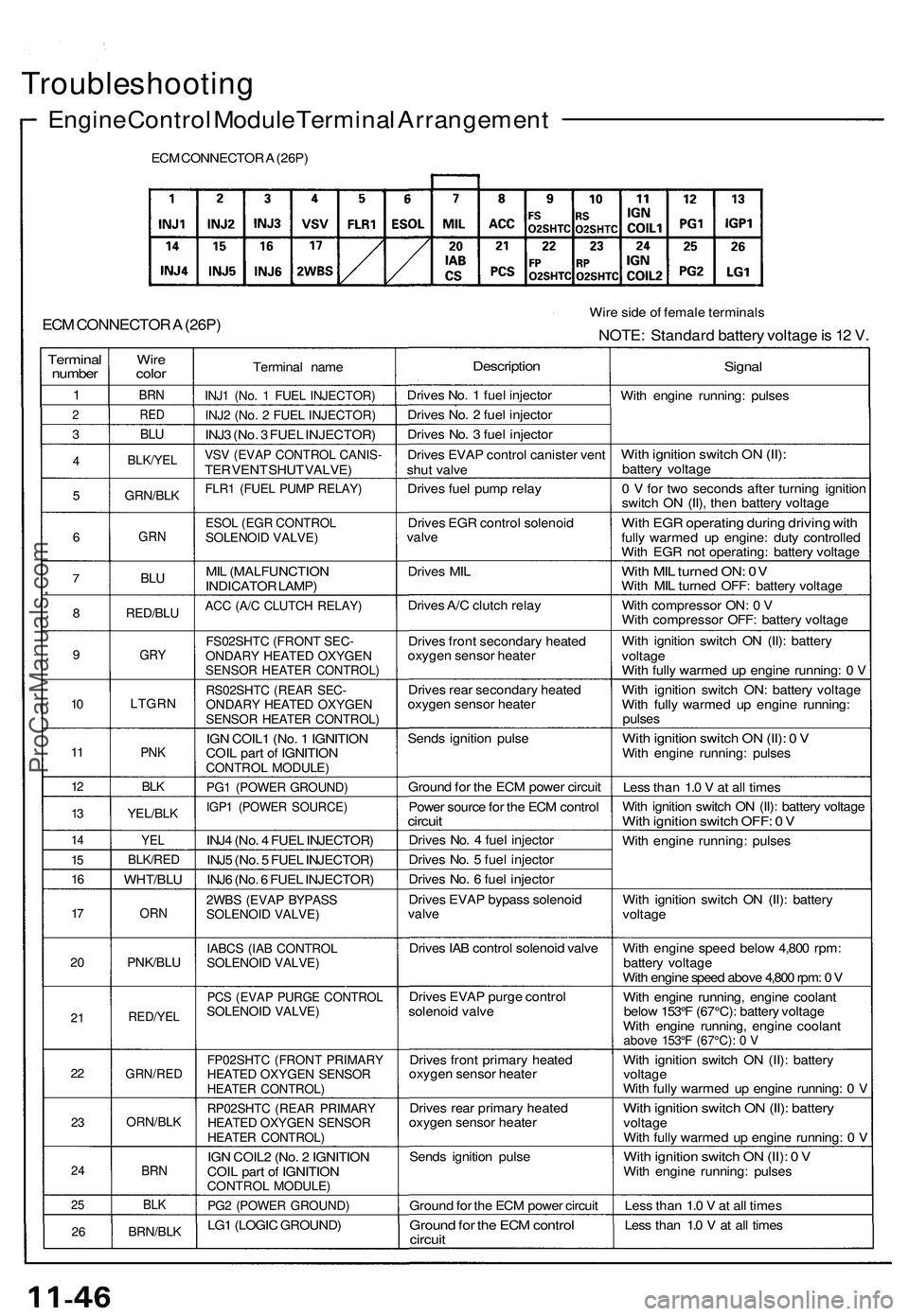
Troubleshooting
Engine Control Module Terminal Arrangement
ECM CONNECTOR A (26P)
ECM CONNECTOR A (26P)
Wire side of female terminals
NOTE: Standard battery voltage is 12 V.
Terminal
number
1
2
3
4
5
6
7
8
9
10
11
12
13
14
15
16
17
20
21
22
23
24
25
26
Wire
color
BRN
RED
BLU
BLK/YEL
GRN/BLK
GRN
BLU
RED/BLU
GRY
LTGRN
PNK
BLK
YEL/BLK
YEL
BLK/RED
WHT/BLU
ORN
PNK/BLU
RED/YEL
GRN/RED
ORN/BLK
BRN
BLK
BRN/BLK
Terminal name
INJ1 (No. 1 FUEL INJECTOR)
INJ2 (No. 2 FUEL INJECTOR)
INJ3 (No. 3 FUEL INJECTOR)
VSV (EVAP CONTROL CANIS-
TER VENT SHUT VALVE)
FLR1 (FUEL PUMP RELAY)
ESOL (EGR CONTROL
SOLENOID VALVE)
MIL (MALFUNCTION
INDICATOR LAMP)
ACC (A/C CLUTCH RELAY)
FS02SHTC (FRONT SEC-
ONDARY HEATED OXYGEN
SENSOR HEATER CONTROL)
RS02SHTC (REAR SEC-
ONDARY HEATED OXYGEN
SENSOR HEATER CONTROL)
IGN COIL1 (No. 1 IGNITION
COIL part of IGNITION
CONTROL MODULE)
PG1 (POWER GROUND)
IGP1 (POWER SOURCE)
INJ4 (No. 4 FUEL INJECTOR)
INJ5 (No. 5 FUEL INJECTOR)
INJ6 (No. 6 FUEL INJECTOR)
2WBS (EVAP BYPASS
SOLENOID VALVE)
IABCS (IAB CONTROL
SOLENOID VALVE)
PCS (EVAP PURGE CONTROL
SOLENOID VALVE)
FP02SHTC (FRONT PRIMARY
HEATED OXYGEN SENSOR
HEATER CONTROL)
RP02SHTC (REAR PRIMARY
HEATED OXYGEN SENSOR
HEATER CONTROL)
IGN COIL2 (No. 2 IGNITION
COIL part of IGNITION
CONTROL MODULE)
PG2 (POWER GROUND)
LG1 (LOGIC GROUND)
Description
Drives No. 1 fuel injector
Drives No. 2 fuel injector
Drives No. 3 fuel injector
Drives EVAP control canister vent
shut valve
Drives fuel pump relay
Drives EGR control solenoid
valve
Drives MIL
Drives A/C clutch relay
Drives front secondary heated
oxygen sensor heater
Drives rear secondary heated
oxygen sensor heater
Sends ignition pulse
Ground for the ECM power circuit
Power source for the ECM control
circuit
Drives No. 4 fuel injector
Drives No. 5 fuel injector
Drives No. 6 fuel injector
Drives EVAP bypass solenoid
valve
Drives IAB control solenoid valve
Drives EVAP purge control
solenoid valve
Drives front primary heated
oxygen sensor heater
Drives rear primary heated
oxygen sensor heater
Sends ignition pulse
Ground for the ECM power circuit
Ground for the ECM control
circuit
Signal
With engine running: pulses
With ignition switch ON (II):
battery voltage
0 V for two seconds after turning ignition
switch ON (II), then battery voltage
With EGR operating during driving with
fully warmed up engine: duty controlled
With EGR not operating: battery voltage
With MIL turned ON: 0V
With MIL turned OFF: battery voltage
With compressor ON: 0 V
With compressor OFF: battery voltage
With ignition switch ON (II): battery
voltage
With fully warmed up engine running: 0 V
With ignition switch ON: battery voltage
With fully warmed up engine running:
pulses
With ignition switch ON (II): 0 V
With engine running: pulses
Less than 1.0 V at all times
With ignition switch ON (II): battery voltage
With ignition switch OFF: 0 V
With engine running: pulses
With ignition switch ON (II): battery
voltage
With engine speed below 4,800 rpm:
battery voltage
With engine speed above 4,800 rpm: 0 V
With engine running, engine coolant
below 153°F (67°C): battery voltage
With engine running, engine coolant
above 153°F (67°C): 0 V
With ignition switch ON (II): battery
voltage
With fully warmed up engine running: 0 V
With ignition switch ON (II): battery
voltage
With fully warmed up engine running: 0 V
With ignition switch ON (II): 0 V
With engine running: pulses
Less than 1.0 V at all times
Less than 1.0 V at all timesProCarManuals.com
Page 574 of 1503
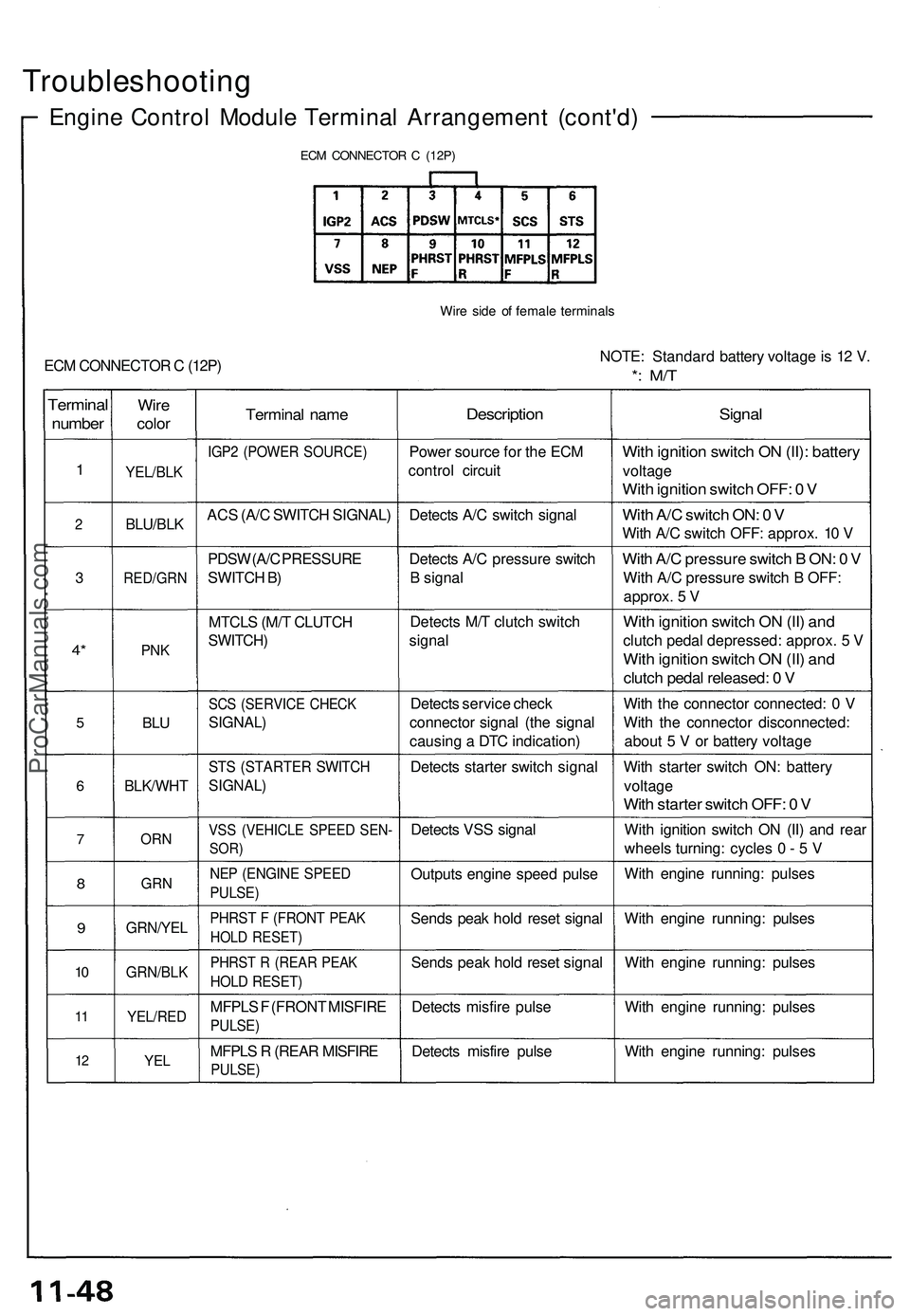
Troubleshooting
Engine Contro l Modul e Termina l Arrangemen t (cont'd )
ECM CONNECTO R C (12P )
Wire sid e o f femal e terminal s
ECM CONNECTO R C (12P ) NOTE
: Standar d batter y voltag e is 1 2 V .*: M/ T
Termina l
number
1
2
3
4*
5
6
7
8
9
10
1 1
1 2
Wir e
colo r
YEL/BL K
BLU/BLK
RED/GR N
PNK
BLU
BLK/WH T
ORN
GR N
GRN/YE L
GRN/BLK
YEL/RED
YEL
Termina l nam e
IGP2 (POWE R SOURCE )
ACS (A/ C SWITC H SIGNAL )
PDS W (A/ C PRESSUR E
SWITC H B )
MTCL S (M/ T CLUTC H
SWITCH )
SCS (SERVIC E CHEC K
SIGNAL )
STS (STARTE R SWITC H
SIGNAL )
VSS (VEHICL E SPEE D SEN -
SOR)
NEP (ENGIN E SPEE D
PULSE )
PHRST F (FRON T PEA K
HOLD RESET )
PHRST R (REA R PEA K
HOLD RESET )
MFPLS F (FRON T MISFIR E
PULSE)
MFPLS R (REA R MISFIR E
PULSE)
Descriptio n
Power sourc e fo r th e EC M
contro l circui t
Detect s A/ C switc h signa l
Detect s A/ C pressur e switc h
B signa l
Detect s M/ T clutc h switc h
signa l
Detect s servic e chec k
connecto r signa l (th e signa l
causin g a DT C indication )
Detect s starte r switc h signa l
Detect s VS S signa l
Output s engin e spee d puls e
Send s pea k hol d rese t signa l
Send s pea k hol d rese t signa l
Detect s misfir e puls e
Detect s misfir e puls e
Signa l
With ignitio n switc h O N (II) : batter y
voltage
With ignitio n switc h OFF : 0 V
Wit h A/ C switc h ON : 0 V
Wit h A/ C switc h OFF : approx . 1 0 V
Wit h A/ C pressur e switc h B ON : 0 V
Wit h A/ C pressur e switc h B OFF :
approx . 5 V
Wit h ignitio n switc h O N (II ) an d
clutc h peda l depressed : approx . 5 V
Wit h ignitio n switc h O N (II ) an d
clutc h peda l released : 0 V
Wit h th e connecto r connected : 0 V
Wit h th e connecto r disconnected :
abou t 5 V or batter y voltag e
Wit h starte r switc h ON : batter y
voltag e
With starte r switc h OFF : 0 V
Wit h ignitio n switc h O N (II ) an d rea r
wheel s turning : cycle s 0 - 5 V
Wit h engin e running : pulse s
Wit h engin e running : pulse s
Wit h engin e running : pulse s
Wit h engin e running : pulse s
Wit h engin e running : pulse s
ProCarManuals.com