1997 ACURA NSX turn signal
[x] Cancel search: turn signalPage 585 of 1503
PGM-FI Syste m
System Descriptio n
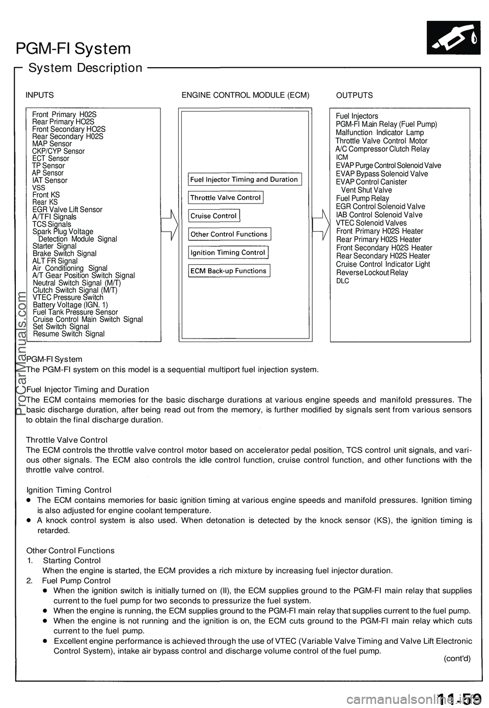
INPUTSENGIN E CONTRO L MODUL E (ECM )OUTPUT S
Front Primar y H02 S
Rea r Primar y HO2 S
Fron t Secondar y HO2 S
Rea r Secondar y H02 S
MA P Senso r
CKP/CY P Senso rECT Senso rTP Senso rAP Senso rIAT Senso rVSSFron t K SRea r K SEG R Valv e Lif t Senso rA/TFI Signal sTCS Signal s
Spar k Plu g Voltag e
Detectio n Modul e Signa l
Starte r Signa l
Brak e Switc h Signa l
AL T F R Signa l
Ai r Conditionin g Signa l
A/ T Gea r Positio n Switc h Signa l
Neutra l Switc h Signa l (M/T )
Clutc h Switc h Signa l (M/T )
VTE C Pressur e Switc h
Batter y Voltag e (IGN . 1 )
Fue l Tan k Pressur e Senso r
Cruis e Contro l Mai n Switc h Signa l
Se t Switc h Signa l
Resum e Switc h Signa l Fue
l Injector s
PGM-F I M.ai n Rela y (Fue l Pump )
Malfunctio n Indicato r Lam p
Throttl e Valv e Contro l Moto r
A/ C Compresso r Clutc h Rela y
ICMEVA P Purg e Contro l Solenoi d Valv e
EVA P Bypas s Solenoi d Valv e
EVA P Contro l Caniste r
Ven t Shu t Valv e
Fue l Pum p Rela y
EG R Contro l Solenoi d Valv e
IA B Contro l Solenoi d Valv e
VTE C Solenoi d Valve s
Fron t Primar y H02 S Heate r
Rea r Primar y H02 S Heate r
Fron t Secondar y H02 S Heate r
Rea r Secondar y H02 S Heate r
Cruis e Contro l Indicato r Ligh t
Revers e Lockou t Rela y
DLC
PGM-F I Syste m
Th e PGM-F I syste m o n thi s mode l i s a sequentia l multipor t fue l injectio n system .
Fue l Injecto r Timin g an d Duratio n
Th e EC M contain s memorie s fo r th e basi c discharg e duration s a t variou s engin e speed s an d manifol d pressures . Th e
basi c discharg e duration , afte r bein g rea d ou t fro m th e memory , i s furthe r modifie d b y signal s sen t fro m variou s sensor s
t o obtai n th e fina l discharg e duration .
Throttl e Valv e Contro l
Th e EC M control s th e throttl e valv e contro l moto r base d o n accelerato r peda l position , TC S contro l uni t signals , an d vari -
ou s othe r signals . Th e EC M als o control s th e idl e contro l function , cruis e contro l function , an d othe r function s wit h th e
throttl e valv e control .
Ignitio n Timin g Contro l
Th e EC M contain s memorie s fo r basi c ignitio n timin g a t variou s engin e speed s an d manifol d pressures . Ignitio n timin g
i s als o adjuste d fo r engin e coolan t temperature .
A knoc k contro l syste m is als o used . Whe n detonatio n i s detecte d b y th e knoc k senso r (KS) , th e ignitio n timin g i s
retarded .
Other Contro l Function s
1 . Startin g Contro l
Whe n th e engin e is started , th e EC M provide s a ric h mixtur e b y increasin g fue l injecto r duration .
2 . Fue l Pum p Contro l
Whe n th e ignitio n switc h i s initiall y turne d o n (II) , th e EC M supplie s groun d t o th e PGM-F I mai n rela y tha t supplie s
curren t t o th e fue l pum p fo r tw o second s t o pressuriz e th e fue l system .
Whe n th e engin e is running , th e EC M supplie s groun d to th e PGM-F I mai n rela y tha t supplie s curren t t o th e fue l pump .
Whe n th e engin e i s no t runnin g an d th e ignitio n i s on , th e EC M cut s groun d t o th e PGM-F I mai n rela y whic h cut s
curren t t o th e fue l pump .
Excellen t engin e performanc e is achieve d throug h th e us e o f VTE C (Variabl e Valv e Timin g an d Valv e Lif t Electroni c
Contro l System) , intak e ai r bypas s contro l an d discharg e volum e contro l o f th e fue l pump .
(cont'd )
ProCarManuals.com
Page 586 of 1503
PGM-FI System
System Description (cont'd)
3. Fuel Cut-off Control
During deceleration with the throttle valve closed, current to the fuel injectors is cut off to improve fuel economy at
speeds over 1,500 rpm.
Fuel cut-off action also takes place when engine speed exceeds 8,300 rpm, regardless of the position of the throttle
valve, to protect the engine from over-revving.
4. A/C Compressor Clutch Relay
When the ECM receives a demand for cooling from the air conditioning system, it delays the compressor from being
energized, and enriches the mixture to assure smooth translation to the A/C mode.
5. Evaporative Emission (EVAP) Purge Control Solenoid Valve
When the engine coolant temperature is below 153°F (67°C), the ECM controls the EVAP purge control solenoid valve
which cuts vacuum to the EVAP purge control canister diaphragm.
6. Intake Air Bypass (IAB) Control Solenoid Valve
When the engine speed is below 4,800 rpm, the IAB control solenoid valve is activated by a signal from the ECM. Intake
air then flows through the smaller chamber, and high torque is delivered. To increase air flow at engine speeds higher
than 4,800 rpm, the solenoid valve is deactivated by the ECM, and the intake air flows through the larger chamber.
7. Exhaust Gas Recirculation (EGR) Control Solenoid Valve
When the EGR is required for control of oxides of nitrogen (NOx) emissions, the ECM supplies ground to the EGR
control solenoid valve which supplies regulated vacuum to the EGR valve.
ECM Fail-safe/Back-up Functions
1. Fail-Safe Function
When an abnormality occurs in a signal from a sensor, the ECM ignores that signal and assumes a pre-programmed
valve for that sensor that allows the engine to continue to run.
2. Back-up Function
When an abnormality occurs in the ECM itself, the fuel injectors are controlled by a back-up circuit independent of the
system in order to permit minimal driving.
3. Self-diagnosis Function [Malfunction Indicator Lamp (MIL)]
When an abnormality occurs in a signal from a sensor, the ECM lights the MIL and stores the diagnostic trouble code
in erasable memory. When the ignition is initially turned on, the ECM supplies ground for the MIL for two seconds to
check the MIL bulb condition.
4. Two Trip Detection Method
To prevent false indications, the Two Trip Detection Method is used for the H02S, fuel metering-related, idle control
system, ECT sensor, EGR system self-diagnostic functions and EVAP control system. When an abnormality occurs,
the ECM stores it in its memory. When the same abnormality recurs after the ignition switch is turned OFF and ON (II)
again, the ECM informs the driver by lighting the MIL.
However, to ease troubleshooting, this function is cancelled when you short the service check connector. The MIL will
then blink immediately when an abnormality occurs.
5. Two (or three) Driving Cycle Detection Method
A "Driving Cycle" consists of starting the engine, beginning closed loop operation, and stopping the engine. If misfir-
ing that increases emissions or EVAP control system malfunction is detected during two consecutive driving cycles,
or TWC deterioration is detected during three consecutive driving cycles, the ECM turns the MIL on.
However,
to
ease
troubleshooting,
this
function
is
cancelled when
you
short
the
service check connector.
The MIL
will
then blink immediately when an abnormality occurs.ProCarManuals.com
Page 587 of 1503
Engine Contro l Modul e (ECM )
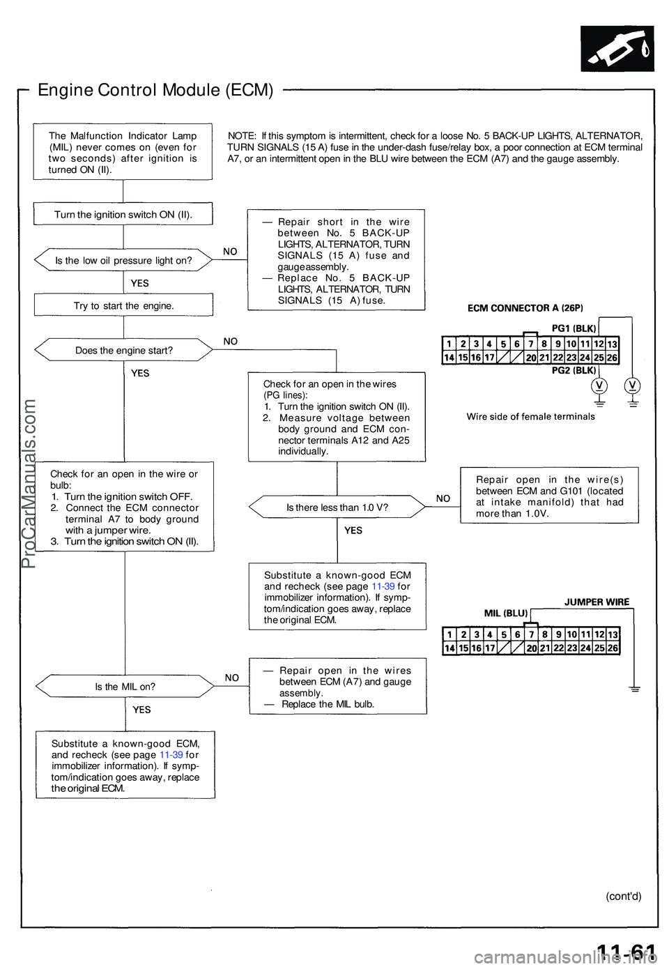
NOTE: I f thi s sympto m is intermittent , chec k fo r a loos e No . 5 BACK-U P LIGHTS , ALTERNATOR ,
TUR N SIGNAL S (1 5 A ) fus e in th e under-das h fuse/rela y box , a poo r connectio n a t EC M termina l
A7 , o r a n intermitten t ope n in th e BL U wir e betwee n th e EC M (A7 ) an d th e gaug e assembly .
I s th e lo w oi l pressur e ligh t on ?
Tr y t o star t th e engine .
Doe s th e engin e start ?
Chec k fo r a n ope n in th e wir e o r
bulb :
1. Tur n th e ignitio n switc h OFF .2. Connec t th e EC M connecto r
termina l A 7 t o bod y groun d
with a jumpe r wire .3. Tur n th e ignitio n switc h O N (II) .
Is th e MI L on ?
Substitut e a known-goo d ECM ,
an d rechec k (se e pag e 11-3 9 fo r
immobilize r information) . I f symp -
tom/indicatio n goe s away , replac e
the origina l ECM .
— Repai r shor t i n the wir e
betwee n No . 5 BACK-U P
LIGHTS , ALTERNATOR , TUR N
SIGNAL S (1 5 A ) fus e an d
gaug e assembly .
— Replac e No . 5 BACK-U P
LIGHTS , ALTERNATOR , TUR N
SIGNALS (15 A) fuse.
Chec k fo r a n ope n in th e wire s
(PG lines) :1. Tur n th e ignitio n switc h O N (II) .
2 . Measur e voltag e betwee n
bod y groun d an d EC M con -
necto r terminal s A1 2 an d A2 5
individually .
I s ther e les s tha n 1. 0 V ?
Substitut e a known-goo d EC M
an d rechec k (se e pag e 11-3 9 fo r
immobilize r information) . I f symp -
tom/indicatio n goe s away , replac e
th e origina l ECM . Repai
r ope n i n th e wire(s )
betwee n EC M an d G10 1 (locate d
a t intak e manifold ) tha t ha d
mor e tha n 1.0V .
— Repai r ope n i n th e wire s
betwee n EC M (A7 ) an d gaug e
assembly .— Replac e th e MI L bulb .
(cont'd )
Turn th e ignitio n switc h O N (II) .
The Malfunctio n Indicato r Lam p
(MIL ) neve r come s o n (eve n fo r
tw o seconds ) afte r ignitio n i s
turne d O N (II) .
ProCarManuals.com
Page 595 of 1503
Idle Contro l Syste m
Alternato r (ALT ) F R Signa l
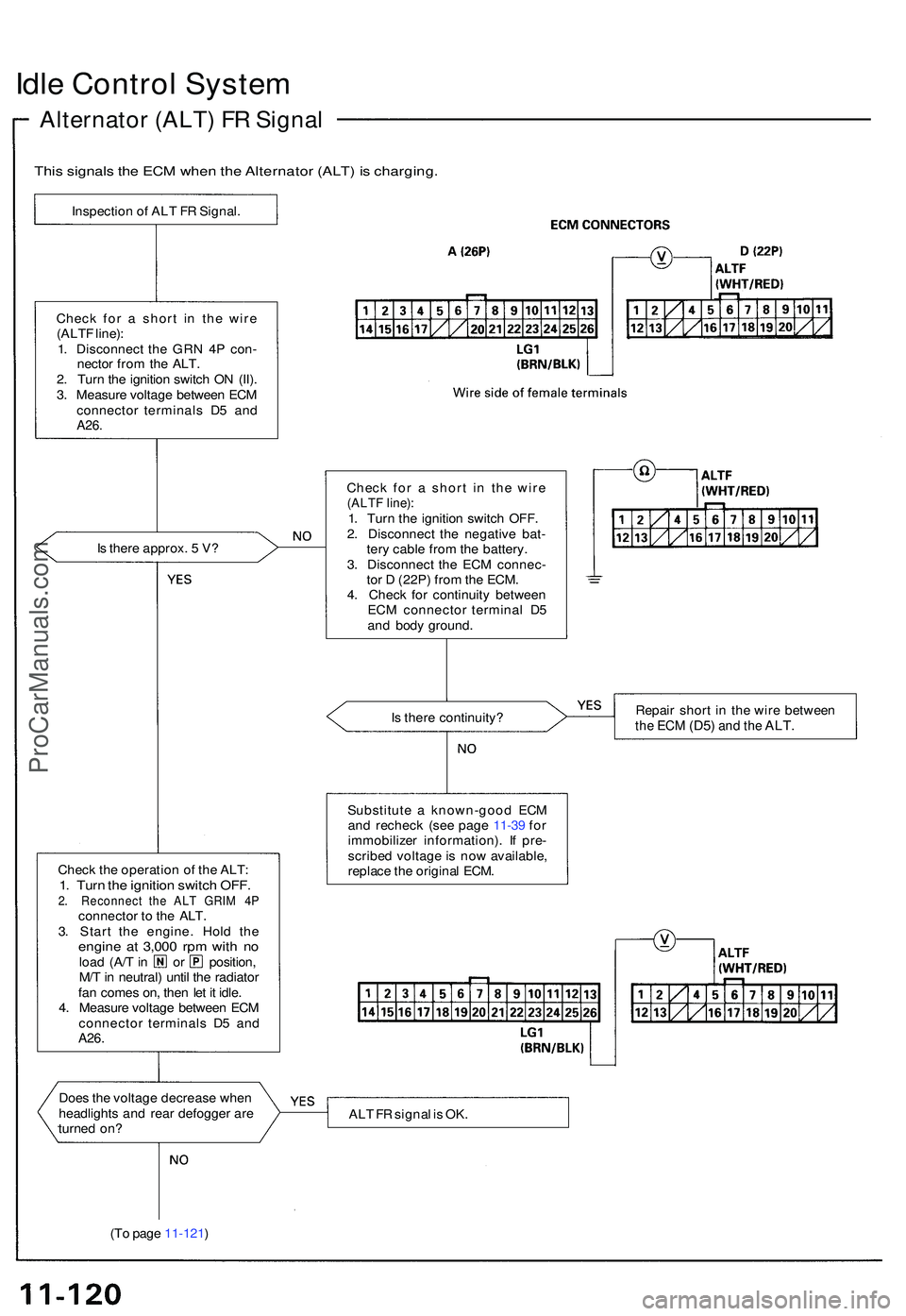
This signal s th e EC M whe n th e Alternato r (ALT ) i s charging .
Inspection o f AL T F R Signal .
Chec k fo r a shor t i n th e wir e
(ALT F line) :
1 . Disconnec t th e GR N 4 P con -
necto r fro m th e ALT .
2 . Tur n th e ignitio n switc h O N (II) .
3 . Measur e voltag e betwee n EC M
connecto r terminal s D 5 an d
A26.
Is ther e approx . 5 V ?
Chec k th e operatio n o f th e ALT :
1. Tur n th e ignitio n switc h OFF .2. Reconnec t th e AL T GRI M 4 Pconnecto r t o th e ALT .
3 . Star t th e engine . Hol d th e
engin e a t 3,00 0 rp m wit h n oloa d (A/ T in o r position ,
M/ T in neutral ) unti l th e radiato r
fa n come s on , the n le t i t idle .
4 . Measur e voltag e betwee n EC M
connecto r terminal s D 5 an d
A26 .
I
Doe s th e voltag e decreas e whe n
headlight s an d rea r defogge r ar e
turne d on ?
(T o pag e 11-121 ) Chec
k fo r a shor t i n th e wir e
(ALT F line) :1. Tur n th e ignitio n switc h OFF .
2 . Disconnec t th e negativ e bat -
ter y cabl e fro m th e battery .
3 . Disconnec t th e EC M connec -
to r D (22P ) fro m th e ECM .
4 . Chec k fo r continuit y betwee n
EC M connecto r termina l D 5
an d bod y ground .
I s ther e continuity ? Repai
r shor t i n th e wir e betwee n
the EC M (D5 ) and th e ALT .
Substitut e a known-goo d EC M
an d rechec k (se e pag e 11-3 9 fo r
immobilize r information) . I f pre -
scribe d voltag e is no w available ,
replac e th e origina l ECM .
AL T F R signa l i s OK .
ProCarManuals.com
Page 628 of 1503
Intake Air System
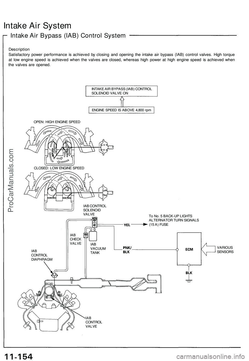
Intake Air Bypass (IAB) Control System
Description
Satisfactory power performance is achieved by closing and opening the intake air bypass (IAB) control valves. High torque
at low engine speed is achieved when the valves are closed, whereas high power at high engine speed is achieved when
the valves are opened.
INTAKE AIR BYPASS (IAB) CONTROL
SOLENOID VALVE ON
ENGINE SPEED IS ABOVE 4,800 rpm
OPEN: HIGH ENGINE SPEED
CLOSED: LOW ENGINE SPEED
IAB CONTROL
SOLENOID
VALVE
To No. 5 BACK-UP LIGHTS
ALTERNATOR TURN SIGNALS
(15 A) FUSE
IAB
CONTROL
DIAPHRAGM
•IAB
CONTROL
VALVE
IAB
CHECK
VALVE
IAB
VACUUM
TANK
VARIOUS
SENSORSProCarManuals.com
Page 634 of 1503
Exhaust Gas Recirculation (EGR) System
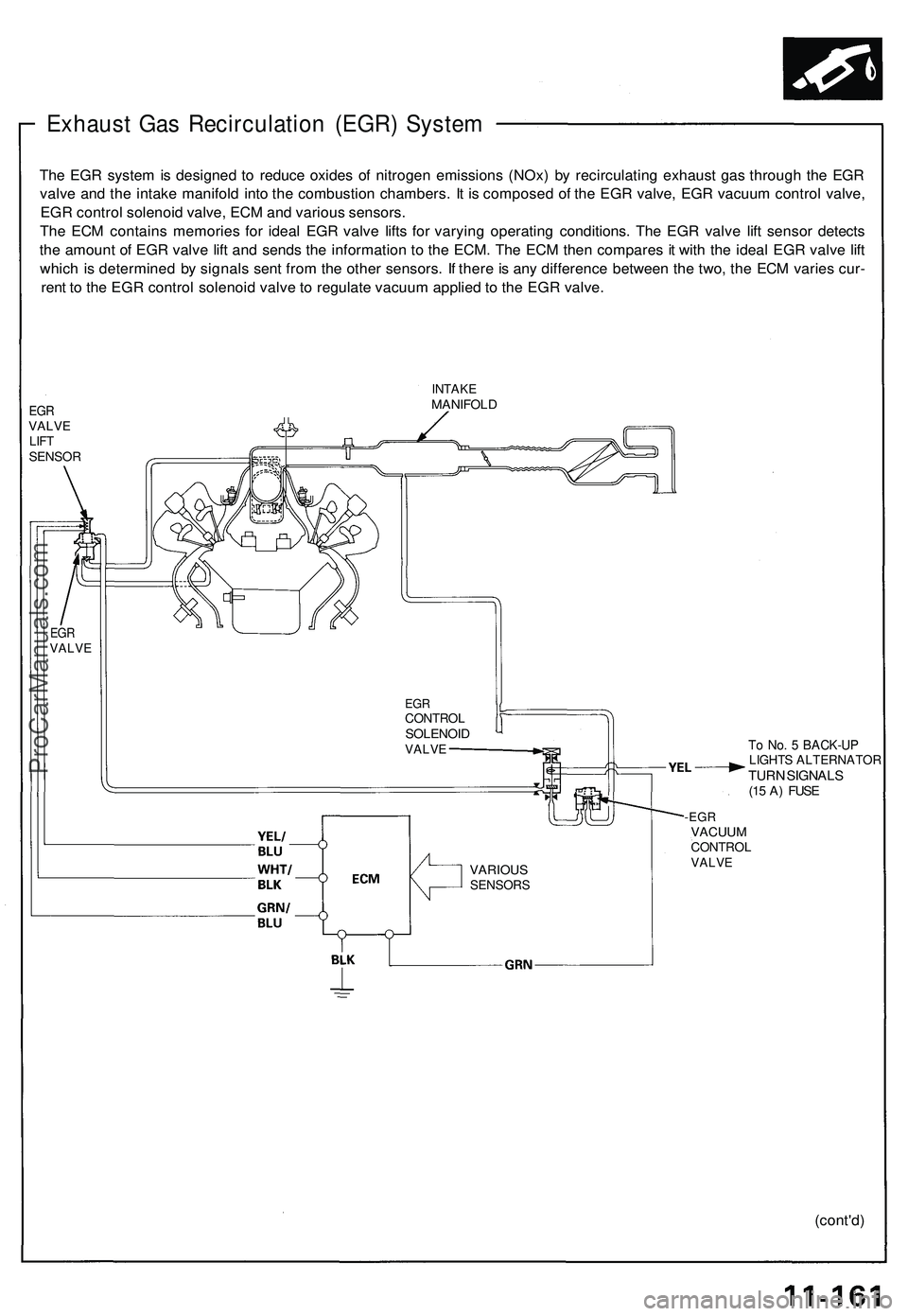
The EGR system is designed to reduce oxides of nitrogen emissions (NOx) by recirculating exhaust gas through the EGR
valve and the intake manifold into the combustion chambers. It is composed of the EGR valve, EGR vacuum control valve,
EGR control solenoid valve, ECM and various sensors.
The ECM contains memories for ideal EGR valve lifts for varying operating conditions. The EGR valve lift sensor detects
the amount of EGR valve lift and sends the information to the ECM. The ECM then compares it with the ideal EGR valve lift
which is determined by signals sent from the other sensors. If there is any difference between the two, the ECM varies cur-
rent to the EGR control solenoid valve to regulate vacuum applied to the EGR valve.
EGR
VALVE
LIFT
SENSOR
INTAKE
MANIFOLD
EGR
CONTROL
SOLENOID
VALVE
To No. 5 BACK-UP
LIGHTS ALTERNATOR
TURN SIGNALS
(15 A) FUSE
-EGR
VACUUM
CONTROL
VALVE
(cont'd)
EGR
VALVE
VARIOUS
SENSORSProCarManuals.com
Page 636 of 1503
Evaporative Emission (EVAP) Controls
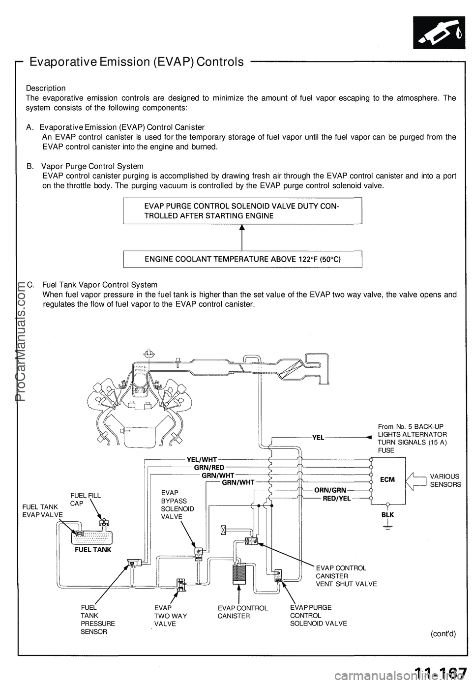
Description
The evaporative emission controls are designed to minimize the amount of fuel vapor escaping to the atmosphere. The
system consists of the following components:
A. Evaporative Emission (EVAP) Control Canister
An EVAP control canister is used for the temporary storage of fuel vapor until the fuel vapor can be purged from the
EVAP control canister into the engine and burned.
B. Vapor Purge Control System
EVAP control canister purging is accomplished by drawing fresh air through the EVAP control canister and into a port
on the throttle body. The purging vacuum is controlled by the EVAP purge control solenoid valve.
C. Fuel Tank Vapor Control System
When fuel vapor pressure in the fuel tank is higher than the set value of the EVAP two way valve, the valve opens and
regulates the flow of fuel vapor to the EVAP control canister.
From No. 5 BACK-UP
LIGHTS ALTERNATOR
TURN SIGNALS (15 A)
FUSE
FUEL TANK
EVAP VALVE
EVAP
BYPASS
SOLENOID
VALVE
VARIOUS
SENSORS
EVAP CONTROL
CANISTER
VENT SHUT VALVE
FUEL
TANK
PRESSURE
SENSOR
EVAP
TWO WAY
VALVE
EVAP CONTROL
CANISTER
EVAP PURGE
CONTROL
SOLENOID VALVE
(cont'd)
FUEL FILL
CAPProCarManuals.com
Page 654 of 1503
Description
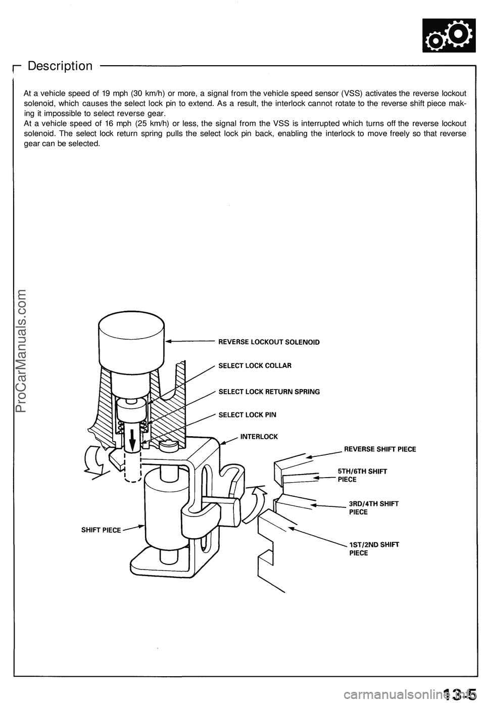
At a vehicle speed of 19 mph (30 km/h) or more, a signal from the vehicle speed sensor (VSS) activates the reverse lockout
solenoid, which causes the select lock pin to extend. As a result, the interlock cannot rotate to the reverse shift piece mak-
ing it impossible to select reverse gear.
At a vehicle speed of 16 mph (25 km/h) or less, the signal from the VSS is interrupted which turns off the reverse lockout
solenoid. The select lock return spring pulls the select lock pin back, enabling the interlock to move freely so that reverse
gear can be selected.ProCarManuals.com