Page 269 of 1503
Lighting Syste m
HID Bulb Removal
1. Mak e sur e yo u hav e th e anti-thef t cod e fo r th e radio ,
the n writ e dow n th e frequencie s fo r th e radio' s prese t
buttons .
2 . Tur n th e combinatio n ligh t switc h OFF .
3 . Disconnec t th e batter y negativ e cable , the n
disconnec t th e positiv e cable .
4 . Remov e th e Tor x bol t usin g a Tor x T2 0 bit .
5 . Tur n th e cove r 45 ° counterclockwis e to remov e it
fro m th e headligh t assembly .
ProCarManuals.com
Page 270 of 1503
6. Turn the socket 45° counterclockwise to remove it
from the bulb.
7. Pull the retaining spring away from the bulb (B), then
remove the bulb.
8. Install the new bulb in the reverse order of removal.
9. After reconnecting the battery, enter the anti-theft
code for the radio, then enter the customer's radio
station presets.ProCarManuals.com
Page 1025 of 1503

Troubleshooting Precautions
ABS Indicator Light:
The ABS indicator light comes on for three seconds and then goes off when the control unit detects no problem during the
initial diagnosis right after the engine starts. The ABS indicator light comes on, and the ABS control unit memorizes the
diagnostic trouble code (DTC) under certain conditions.
• The parking brake is applied for more than 30 seconds while the vehicle is being driven. (DTC 2-1)
• The vehicle loses traction when starting from a stuck condition on a muddy, snowy, or sandy road. (DTC 4-1, 4-2, 4-4, 4-8)
• The vehicle loses traction, and the front wheels spin for more than one minute when starting from a stuck condition on
a muddy, snowy, or sandy road. (DTC 4-8)
• Tire adhesion is lost due to excessive cornering speed. (DTC 5, 5-4, 5-8)
• The vehicle is interfered by strong radio waves (noise), for example, illegal radio, etc. (DTC 8-2)
NOTE: If there is any trouble in the system, the ABS indicator light comes on during driving.
Diagnostic Trouble Code (DTC):
• When the control unit detects a problem and the ABS indicator light comes on, the control unit memorizes the DTC.
• The control unit has three memory registers. When a problem occurs, the control unit stores the DTC in the first memory
register.
• The most recent DTC is indicated first, and the oldest DTC is indicated last.
• The DTCs are erased from the control unit when the ABS control unit +B2 power supply or connector is disconnected.
• The control unit's memory can be erased by disconnecting the ABS 2, 3 fuse for more than three seconds.
Self-diagnosis:
• There are two self-diagnoses described below.
Initial diagnosis: Performed right after the engine starts until the ABS indicator light goes off.
Regular diagnosis: Continuously performed (under some conditions) after the ABS indicator light goes off until the
engine stops.
• The CPU (central processing unit) controls the following when it detects a problem during self-diagnosis:
Turns the ABS indicator light ON.
Turns the front and rear fail-safe relays off.
Stops the ABS control.
Stops the ABS pump.
After the DTC is stored in the control unit, the CPU stops self-diagnosis.ProCarManuals.com
Page 1112 of 1503
Climate control unit, stereo cassette/radio and glove box removal:
Disassemble in numbered sequence.
NOTE: Remove the center console panel.
CLIMATE CONTROL
UNIT
Disconnect the connectors.
SRS UNIT
Passenger's:
STEREO
CASSETTE RADIO
Disconnect the connectors.
GROUND CABLE
GLOVE BOX
Disconnect the connectors.
TRUNK LID OPENER
MAIN SWITCH
PASSENGER'S
AIRBAG
DLC
CONNECTOR
GLOVE BOX
LID
DASHBOARD LOWER
COVER (Passenger's)
Installation is the reverse of the removal procedure.
NOTE: Make sure the connectors are connected properly.
(cont'd)ProCarManuals.com
Page 1382 of 1503
Stereo Soun d Syste m
Componen t Locatio n Inde x
SRS component s ar e locate d i n thi s area . Revie w th e
SR S componen t locations , precautions , an d procedure s
i n th e SR S ( sectio n 24 ) befor e performin g repair s o r ser -
vice .
UNDER-HOO DRELAY BO X A
STERE O RADIO/CASSETT E PLAYE R
• Removal , pag e 23-24 0
• Terminals , pag e 23-24 2
FOO T WEL L BAS S SPEAKE R
Replacement , pag e 23-247
POWE R AMPLIFIE R RELA Y
Wir e colors : YEL/RED ,
GRN/BLK , PNK/WHT , BL K
Test , pag e 23-24 2 PASSENGER'
S DOO R SPEAKE R
Replacement , pag e 23-24 7
DRIVER'SDOO RSPEAKERReplacement , pag e 23-24 7
REAR SPEAKE RReplacement , pag e 23-24 7
POWE R ANTENN A MOTO R
• Test , pag e 23-24 3
• Replacement , pag e 23-24 4
WINDO W ANTENN A
MAST ANTENN A LEA D WINDO
W ANTENN A
LEAD
ProCarManuals.com
Page 1384 of 1503
5. Remove the five screws and center console panel,
then disconnect the 3P connector and 4P connector
from the floor wire harness.
CENTER CONSOLE PANEL
4P
CONNECTOR
3P CONNECTOR
6. Remove the four screws, then disconnect the 14P
and 30P connectors from the floor wire harness and
take out the climate control unit.
CLIMATE
CONTROL UNIT
30P CONNECTOR
14P CONNECTOR
7. Remove the four screws, then disconnect the 16P
connector, mast antenna lead, and window antenna
lead and take out the stereo radio/cassette player.
STEREO RADIO/
CASSETTE PLAYER
16P CONNECTOR
WINDOW ANTENNA LEAD
MAST ANTENNA LEADProCarManuals.com
Page 1385 of 1503

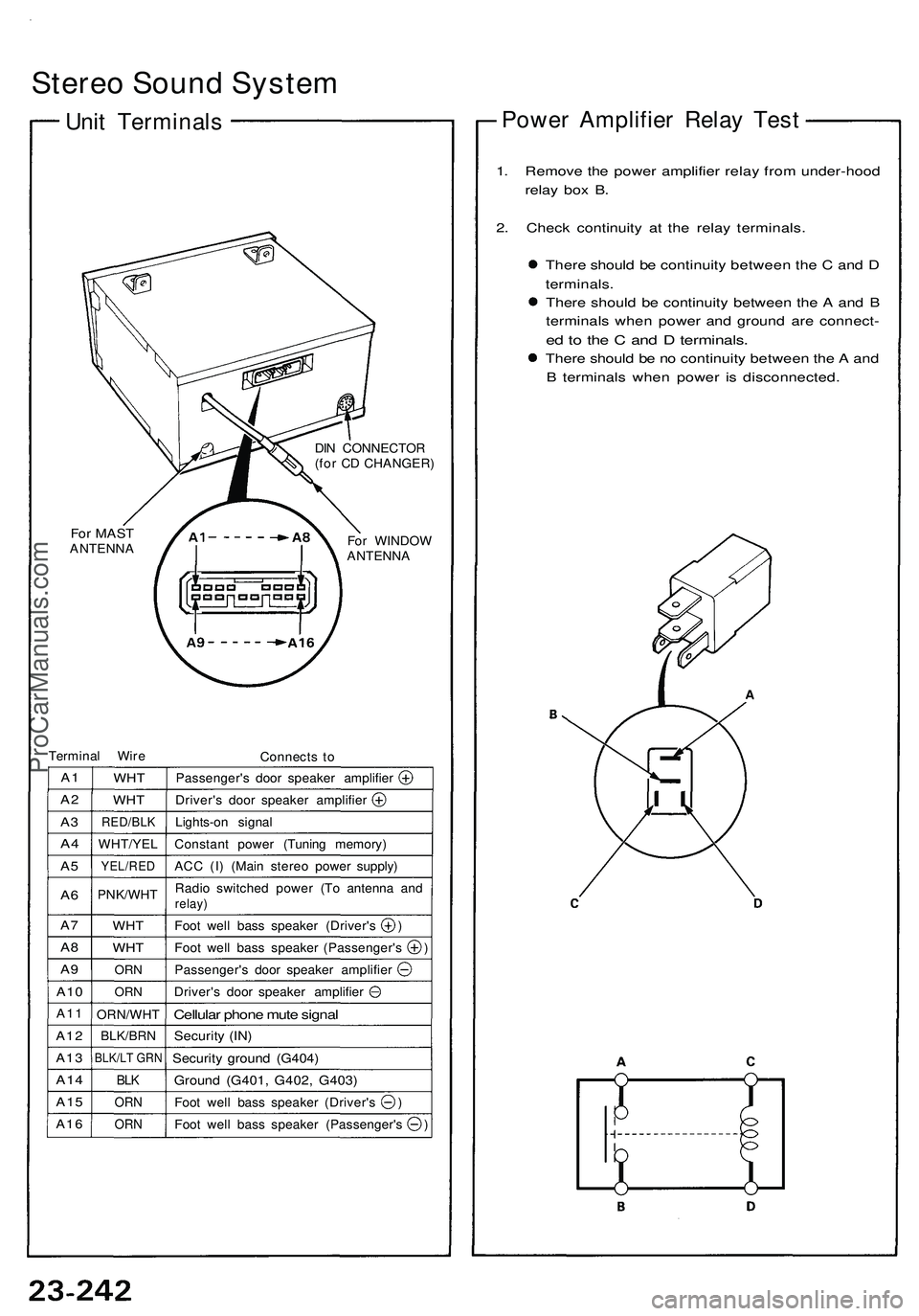
Stereo Sound System
Unit Terminals
For MAST
ANTENNA
DIN CONNECTOR
(for CD CHANGER)
For WINDOW
ANTENNA
Terminal Wire
Connects to
A1
A2
A3
A4
A5
A6
A7
A8
A9
A10
A11
A12
A13
A14
A15
A16
WHT
WHT
RED/BLK
WHT/YEL
YEL/RED
PNK/WHT
WHT
WHT
ORN
ORN
ORN/WHT
BLK/BRN
BLK/LT GRN
BLK
ORN
ORN
Passenger's door speaker amplifier
Driver's door speaker amplifier
Lights-on signal
Constant power (Tuning memory)
ACC (I) (Main stereo power supply)
Radio switched power (To antenna and
relay)
Foot well bass speaker (Driver's )
Foot well bass speaker (Passenger's )
Passenger's door speaker amplifier
Driver's door speaker amplifier
Cellular phone mute signal
Security (IN)
Security ground (G404)
Ground (G401, G402, G403)
Foot well bass speaker (Driver's )
Foot well bass speaker (Passenger's )
Power Amplifier Relay Test
1. Remove the power amplifier relay from under-hood
relay box B.
2. Check continuity at the relay terminals.
There should be continuity between the C and D
terminals.
There should be continuity between the A and B
terminals when power and ground are connect-
ed to the C and D terminals.
There should be no continuity between the A and
B terminals when power is disconnected.ProCarManuals.com
Page 1386 of 1503
— Power Antenna Motor Test
1. Open the trunk lid, and remove the side trim panel.
2. Disconnect the 4P connector from the motor, and
check power to the motor at the connector termi-
nals:
There should be battery voltage between the
WHT/BLU (+) and BLK (-) terminals all the time.
There should be battery voltage between the
PNK/WHT (+) and BLK (-) terminals only with
the ignition and radio switched ON.
WHT/BLU BLK
View from wire side
3. Test motor operation:
FULL EXTEND: Connect battery power to the No.
3 and No. 4 terminals and ground
to the No. 2 terminal.
RETRACT: Disconnect power from the No. 3
terminal.
4. If the motor fails to operate properly, replace it.
MAST
ANTENNA
MAST
ANTENNA
LEAD
POWER ANTENNA MOTOR
(With the antenna retracted fully)
GRN/REDProCarManuals.com