Page 6 of 1503

Warning/Caution Labe l Location s
K: PASSENGER'S INFLATOR CAUTION
DANGEREXPLOSIVE/FLAMMABL E
CONTAC T WIT H ACID , WATER , O R HEAV Y METAL S SUC H
A S COPPER , LEAD , O R MERCUR Y MA Y PRODUC E HARM -
FU L AN D IRRITATIN G GASE S O R EXPLOSIV E COM -
POUNDS .STORAG E TEMPERATURE S MUS T NO T EXCEE D 200° F
(10 0 C) . FO R PROPE R HANDLING , STORAGE , AN D DISPOSA L
PROCEDURES , REFE R T O SERVIC E MANUAL , SR S SUPPLE -
MENTPOISO NCONTAIN S POISONOU S SODIU M AZIDE AND POTASSIU M
NITRATE .
FIRS T AI D
I F CONTENT S AR E SWALLOWED , INDUC E VOMITING .
FO R EY E CONTACT , FLUS H EYE S WIT H WATE R FO R 1 5
MINUTES .IF GASE S (FRO M ACI D O R WATE R CONTACT ) AR E
INHALED , SEE K FRES H AIR . I N EVER Y CASE , GE T PROMP T
MEDICA L ATTENTION .
KEE P OU T O F REAC H O F CHILDREN .
WARNIN G
TH E AIRBA G INFLATO R IS EXPLOSIVE , AND , I F ACCIDEN -
TALL Y DEPLOYED , CA N SERIOUSL Y HUR T O R KIL L YOU .
• D O NO T US E ELECTRICA L TES T EQUIPMEN T O R PROB -
IN G DEVICES .
THE Y CA N CAUS E ACCIDENTA L DEPLOYMENT .
• N O SERVICEABL E PART S INSIDE . D O NO T DISASSEM -
BLE.• PLAC E AIRBA G UPRIGH T WHE N REMOVED .
• FOLLO W SERVIC E MANUA L INSTRUCTION S CAREFULLY .
L : TENSIONE R POWE R SOURC E CAUTIO N
SEA T BEL T TENSIONE R
D O NO T TAMPER , REFE R T O SERVIC E MANUA L FO R COM -
PLET E INSTRUCTIONS . M
: TENSIONE R EL R CAUTIO N
WARNIN G
EXPLOSIV E MATERIA L INSID E
YO U CA N B E SERIOUSL Y HUR T O R BURNED .
• INSTAL L RE D SHOR T CONNECTO R WHE N WIR E HAR -
NES S IS DISCONNECTED .
• D O NO T TAMPE R O R DISASSEMBLE .
N O SERVICEABL E PART S INSIDE .
• US E ONL Y APPROVE D ELECTRICA L TESTER S FO R CIR -
CUI T DIAGNOSIS .
REFE R T O SERVIC E MANUA L FO R COMPLET E
INSTRUCTIONS .
N : SR S WARNIN G (HOOD )
SUPPLEMENTA L RESTRAIN T SYSTE M (SRS )
THI S VEHICL E I S EQUIPPE D WIT H DRIVE R AN D FRON T
SEA T PASSENGE R AIRBAG S AN D FRON T SEA T BEL T TEN -
SIONE R SYSTEMS .
AL L SR S ELECTRICA L WIRIN G AN D CONNECTOR S AR E
COLORE D YELLOW .
TAMPERIN G WITH , DISCONNECTIN G O R USIN G ELECTRI -
CA L TES T EQUIPMEN T O N TH E SR S WIRIN G CA N MAK E
TH E SYSTE M INOPERATIV E O R CAUS E ACCIDENTA L FIR -
IN G O F TH E INFLATOR .
WARNIN G
TH E AIRBA G INFLATO R IS EXPLOSIV E AND , I F ACCIDEN -
TALL Y DEPLOYED , CA N SERIOUSL Y HUR T YOU .
FOLLO W SERVIC E MANUA L INSTRUCTION S CAREFULLY .
ProCarManuals.com
Page 892 of 1503
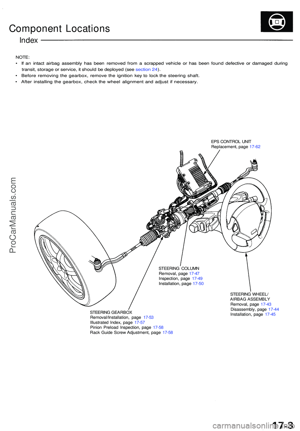
Component Location s
Index
NOTE :
• I f a n intac t airba g assembl y ha s bee n remove d fro m a scrappe d vehicl e o r ha s bee n foun d defectiv e o r damage d durin g
transit , storag e o r service , i t shoul d b e deploye d (se e sectio n 24 ).
• Befor e removin g th e gearbox , remov e th e ignitio n ke y t o loc k th e steerin g shaft .
• Afte r installin g th e gearbox , chec k th e whee l alignmen t an d adjus t i f necessary .
STEERING GEARBO XRemoval/Installation , pag e 17-5 3
Illustrate d Index , pag e 17-5 7
Pinio n Preloa d Inspection , pag e 17-5 8
Rac k Guid e Scre w Adjustment , pag e 17-5 8
STEERIN
G COLUM N
Removal , pag e 17-4 7
Inspection , pag e 17-4 9
Installation , pag e 17-5 0
STEERIN G WHEEL /AIRBAG ASSEMBL YRemoval, pag e 17-4 3
Disassembly , pag e 17-4 4
Installation , pag e 17-4 5
EP
S CONTRO L UNI T
Replacement , pag e 17-62
ProCarManuals.com
Page 914 of 1503
Steering Whee l
Remova l
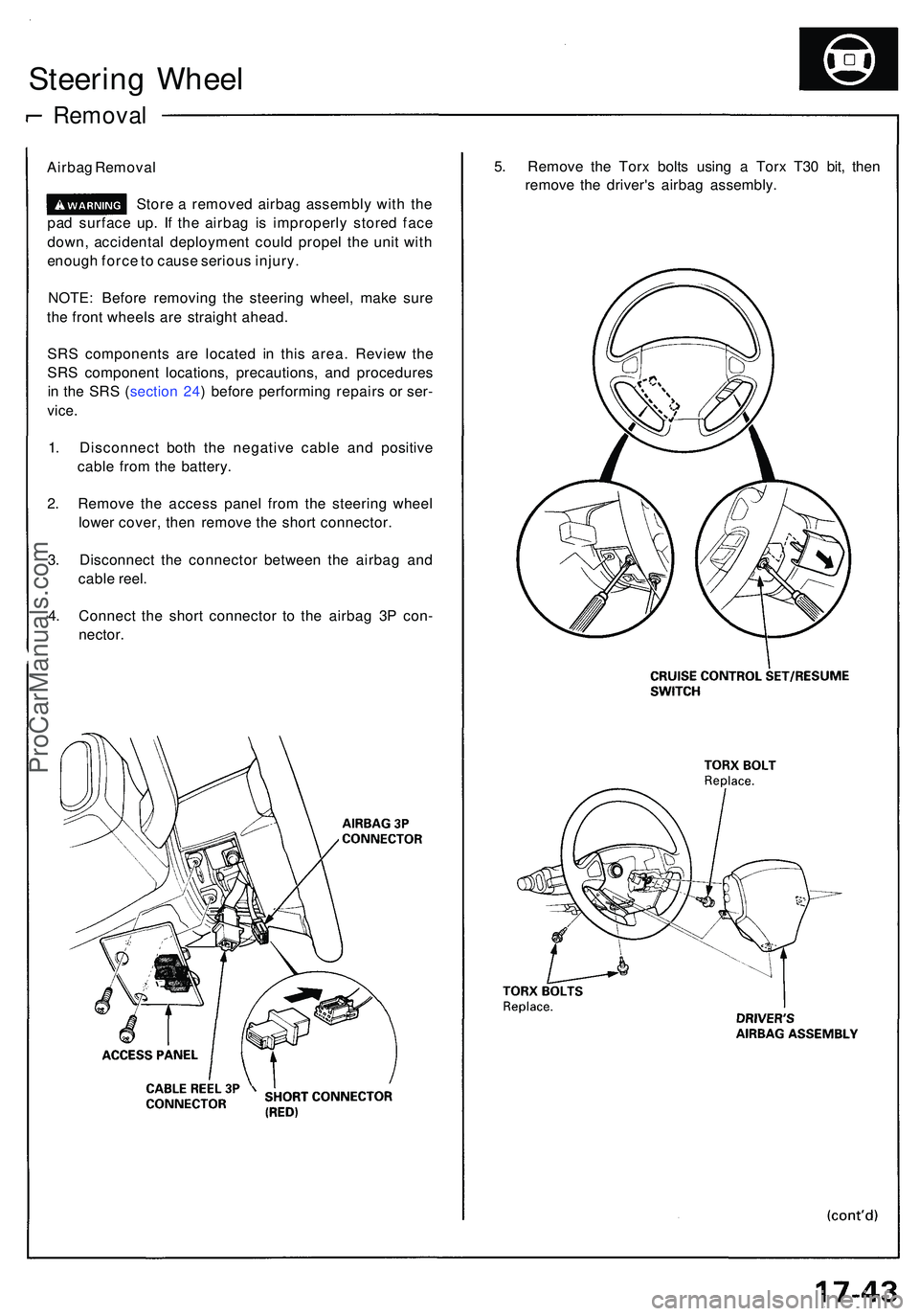
Airbag Remova l
Stor e a remove d airba g assembl y wit h th e
pa d surfac e up . I f th e airba g i s improperl y store d fac e
down , accidenta l deploymen t coul d prope l th e uni t wit h
enoug h forc e to caus e seriou s injury .
NOTE : Befor e removin g th e steerin g wheel , mak e sur e
th e fron t wheel s ar e straigh t ahead .
SR S component s ar e locate d i n thi s area . Revie w th e
SR S componen t locations , precautions , an d procedure s
i n th e SR S ( sectio n 24 ) befor e performin g repair s o r ser -
vice .
1. Disconnec t bot h th e negativ e cabl e an d positiv e
cabl e fro m th e battery .
2 . Remov e th e acces s pane l fro m th e steerin g whee l
lowe r cover , the n remov e th e shor t connector .
3 . Disconnec t th e connecto r betwee n th e airba g an d
cabl e reel .
4 . Connec t th e shor t connecto r t o th e airba g 3 P con -
nector .
5. Remov e th e Tor x bolt s usin g a Tor x T3 0 bit , the n
remov e th e driver' s airba g assembly .
ProCarManuals.com
Page 916 of 1503
Steering Whee l
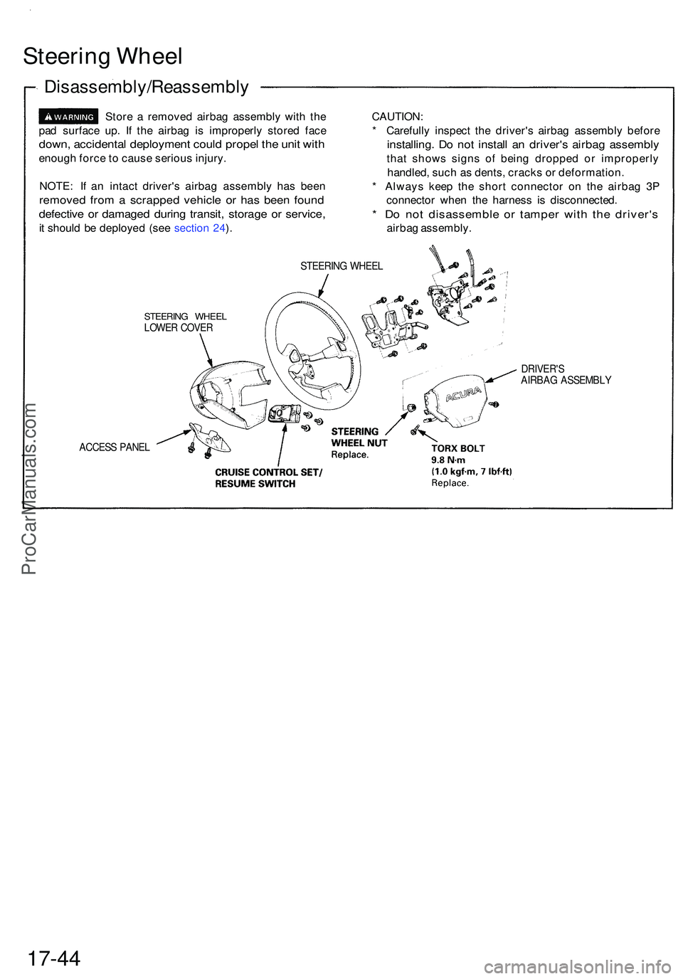
Disassembly/Reassembl y
Store a remove d airba g assembl y wit h th e
pa d surfac e up . I f th e airba g i s improperl y store d fac e
down , accidenta l deploymen t coul d prope l th e uni t wit h
enoug h forc e to caus e seriou s injury .
NOTE : I f a n intac t driver' s airba g assembl y ha s bee n
remove d fro m a scrappe d vehicl e o r ha s bee n foun d
defectiv e o r damage d durin g transit , storag e o r service ,
it shoul d b e deploye d (se e sectio n 24 ). CAUTION
:
* Carefull y inspec t th e driver' s airba g assembl y befor e
installing . D o no t instal l a n driver' s airba g assembl y
that show s sign s o f bein g droppe d o r improperl y
handled , suc h a s dents , crack s o r deformation .
* Alway s kee p th e shor t connecto r o n th e airba g 3 P
connecto r whe n th e harnes s i s disconnected .
* D o no t disassembl e o r tampe r wit h th e driver' s
airbag assembly .
STEERING WHEE L
STEERIN G WHEE LLOWER COVE R
ACCES S PANE L
DRIVER' SAIRBAG ASSEMBL Y
17-44
ProCarManuals.com
Page 917 of 1503
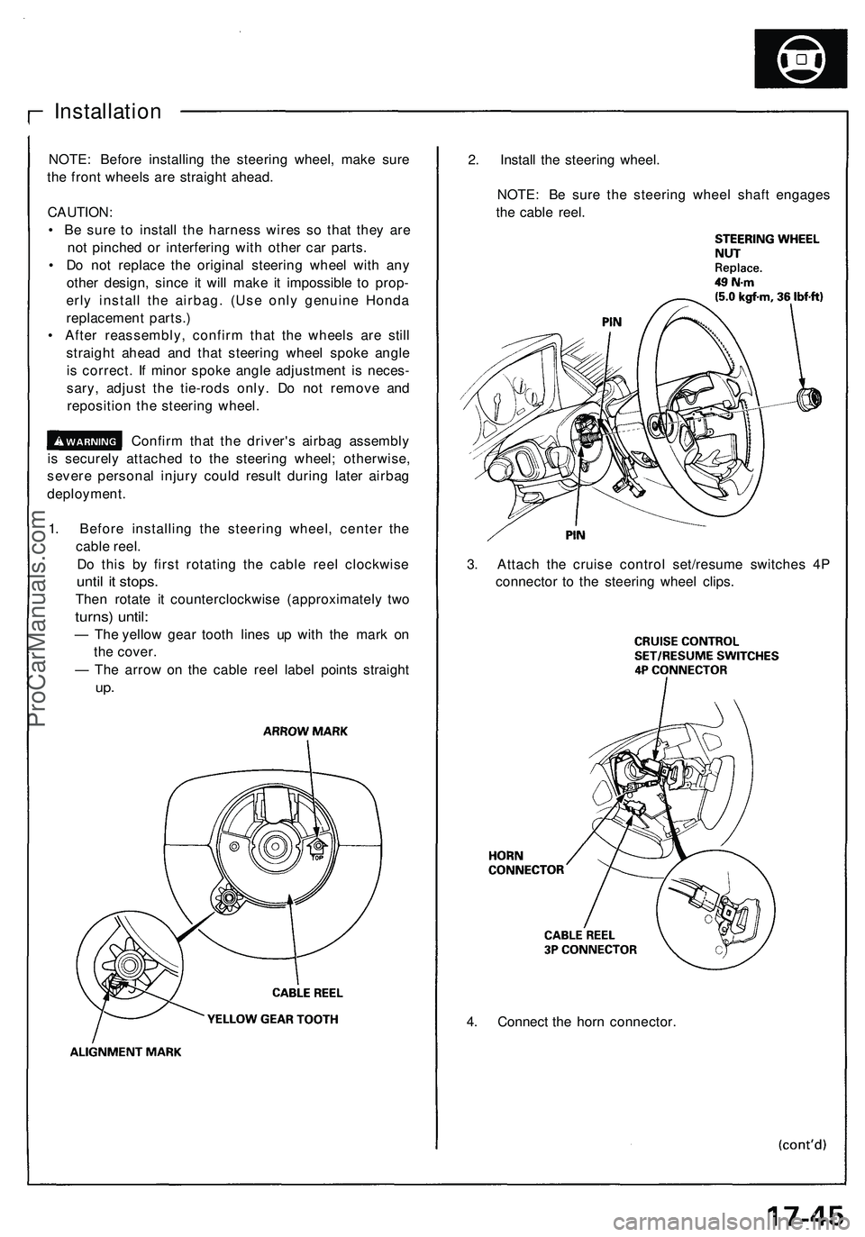
4. Connect the horn connector.
Installation
NOTE: Before installing the steering wheel, make sure
the front wheels are straight ahead.
CAUTION:
• Be sure to install the harness wires so that they are
not pinched or interfering with other car parts.
• Do not replace the original steering wheel with any
other design, since it will make it impossible to prop-
erly install the airbag. (Use only genuine Honda
replacement parts.)
• After reassembly, confirm that the wheels are still
straight ahead and that steering wheel spoke angle
is correct. If minor spoke angle adjustment is neces-
sary, adjust the tie-rods only. Do not remove and
reposition the steering wheel.
Confirm that the driver's airbag assembly
is securely attached to the steering wheel; otherwise,
severe personal injury could result during later airbag
deployment.
1. Before installing the steering wheel, center the
cable reel.
Do this by first rotating the cable reel clockwise
until it stops.
Then rotate it counterclockwise (approximately two
turns) until:
— The yellow gear tooth lines up with the mark on
the cover.
— The arrow on the cable reel label points straight
up.
2. Install the steering wheel.
NOTE: Be sure the steering wheel shaft engages
the cable reel.
3. Attach the cruise control set/resume switches 4P
connector to the steering wheel clips.ProCarManuals.com
Page 1112 of 1503
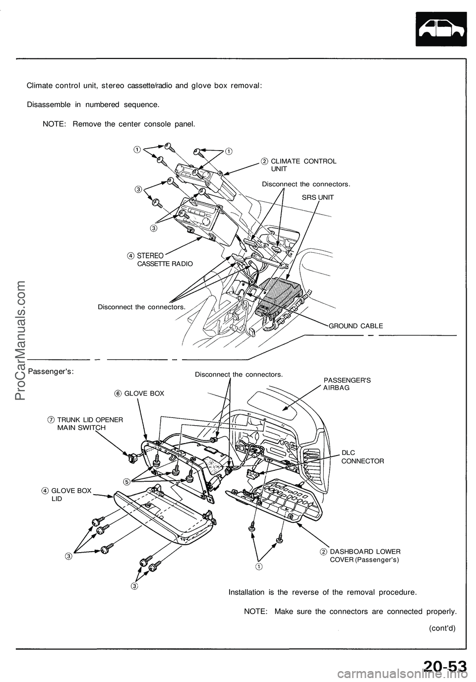
Climate control unit, stereo cassette/radio and glove box removal:
Disassemble in numbered sequence.
NOTE: Remove the center console panel.
CLIMATE CONTROL
UNIT
Disconnect the connectors.
SRS UNIT
Passenger's:
STEREO
CASSETTE RADIO
Disconnect the connectors.
GROUND CABLE
GLOVE BOX
Disconnect the connectors.
TRUNK LID OPENER
MAIN SWITCH
PASSENGER'S
AIRBAG
DLC
CONNECTOR
GLOVE BOX
LID
DASHBOARD LOWER
COVER (Passenger's)
Installation is the reverse of the removal procedure.
NOTE: Make sure the connectors are connected properly.
(cont'd)ProCarManuals.com
Page 1114 of 1503
Replacement
SRS component s ar e locate d in thi s area . Revie w th e SR S
componen t locations , precautions , an d procedure s i n th e
SR S ( sectio n 24 ) befor e performin g repair s o r service .
1 . T o remov e th e dashboard , firs t remov e the :
Seat s (se e pag e 20-39 )
Dashboar d lowe r cove r (Driver's ) (se e pag e
20-54 )
Dashboar d lowe r pa d (se e pag e 20-54 )
Dashboar d brac e (se e pag e 20-54 )
Cente r armres t (se e pag e 20-49 )
Clock , cente r ai r ven t an d consol e pane l (se e
page s 20-50 , 20-51 , 20-52 )
• Climat e contro l uni t an d stere o cassette/radi o (se e
pag e 20-53 )
• Dashboar d lowe r cove r (Passenger's ) (se e pag e
20-53 )
• Glov e bo x li d an d glov e bo x (se e pag e 20-53 )
2 . Lowe r th e steerin g colum n (se e sectio n 17 ).
T o avoi d accidenta l deploymen t an d
possibl e injur y alway s instal l th e shor t connecto r
o n th e airba g connecto r whe n th e SR S wir e
harnes s i s disconnected .
NOTE:
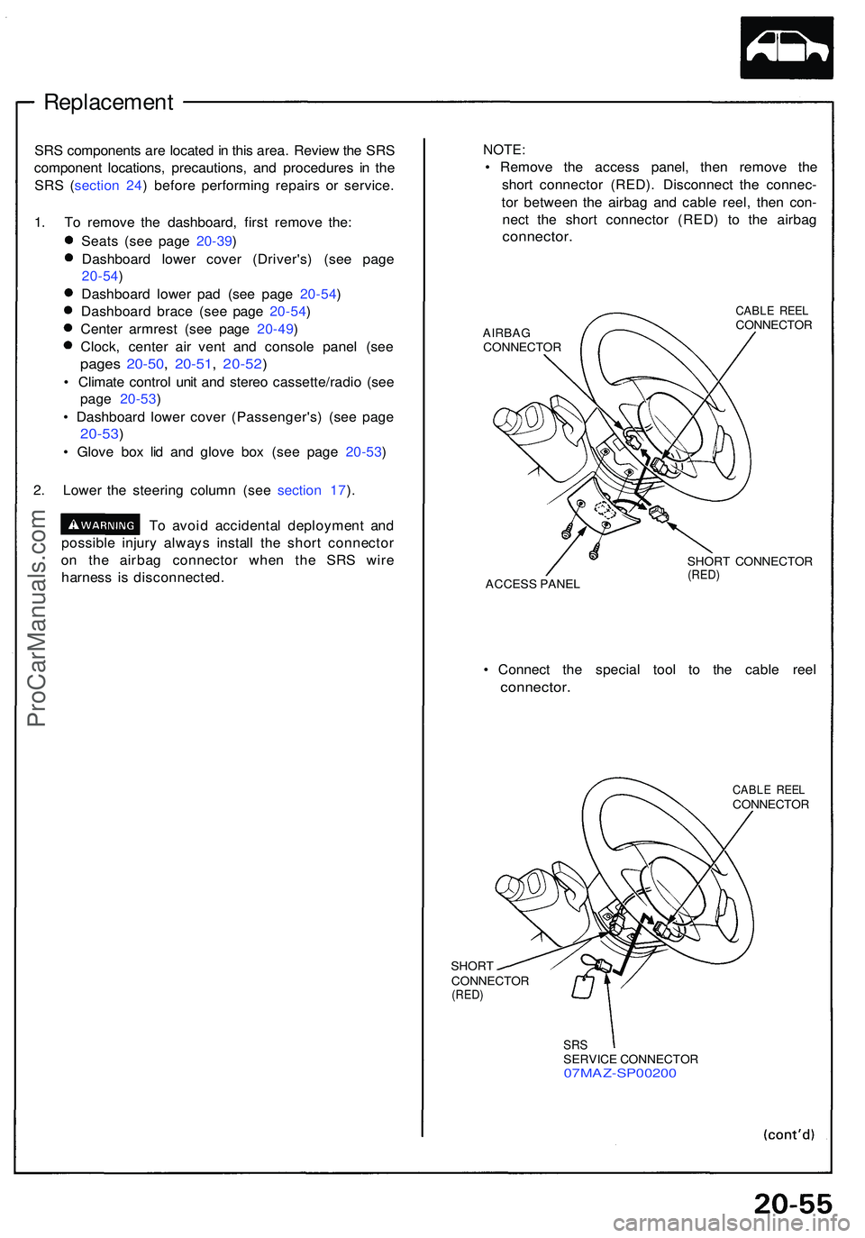
• Remov e th e acces s panel , the n remov e th e
shor t connecto r (RED) . Disconnec t th e connec -
to r betwee n th e airba g an d cabl e reel , the n con -
nec t th e shor t connecto r (RED ) t o th e airba g
connector .
AIRBAGCONNECTO R
CABLE REE LCONNECTO R
ACCES S PANE L SHOR
T CONNECTO R
(RED)
• Connec t th e specia l too l t o th e cabl e ree l
connector .
SHORT
CONNECTO R
(RED)
CABL E REE LCONNECTO R
SRSSERVIC E CONNECTO R07MAZ-SP0020 0
ProCarManuals.com
Page 1116 of 1503
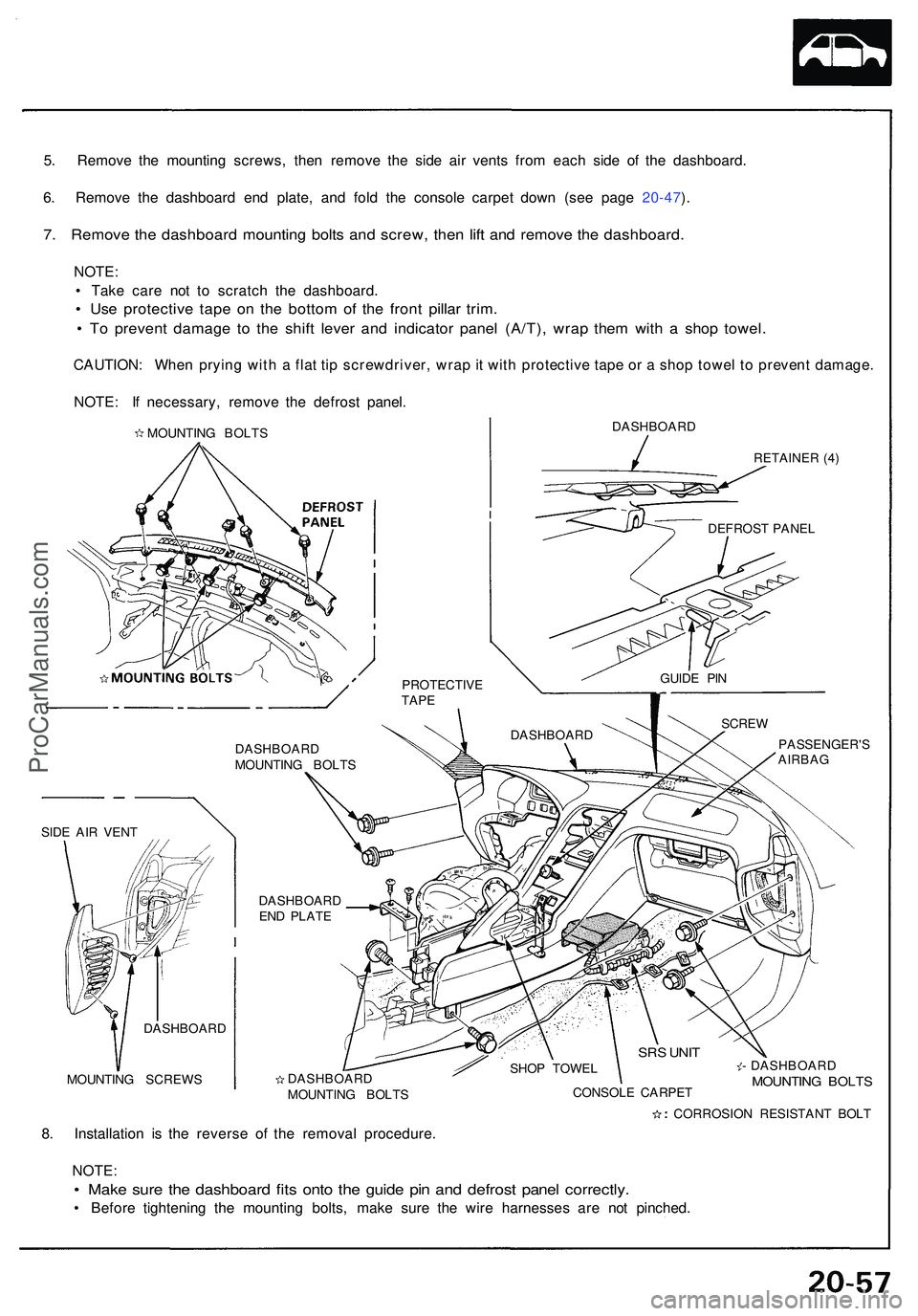
5. Remov e th e mountin g screws , the n remov e th e sid e ai r vent s fro m eac h sid e o f th e dashboard .
6 . Remov e th e dashboar d en d plate , an d fol d th e consol e carpe t dow n (se e pag e 20-47 ).
7 . Remov e th e dashboar d mountin g bolt s an d screw , the n lif t an d remov e th e dashboard .
NOTE:
• Tak e car e no t t o scratc h th e dashboard .
• Us e protectiv e tap e o n th e botto m o f th e fron t pilla r trim .
• T o preven t damag e t o th e shif t leve r an d indicato r pane l (A/T) , wra p the m wit h a sho p towel .
CAUTION : Whe n pryin g wit h a fla t ti p screwdriver , wra p it wit h protectiv e tap e o r a sho p towe l t o preven t damage .
NOTE : I f necessary , remov e th e defros t panel .
DASHBOAR D
RETAINER (4 )
DASHBOAR D
MOUNTIN G BOLT S
DASHBOAR D
EN D PLAT E
MOUNTIN G SCREW S PASSENGER'
S
AIRBAG
DASHBOAR DMOUNTING BOLT S SHO
P TOWE L
CONSOL E CARPE T - DASHBOAR
D MOUNTING BOLT S
8. Installatio n i s th e revers e of the remova l procedure .
NOTE :
• Mak e sur e th e dashboar d fit s ont o th e guid e pi n an d defros t pane l correctly .
• Befor e tightenin g th e mountin g bolts , mak e sur e th e wir e harnesse s ar e no t pinched .
PROTECTIV ETAPE
DASHBOAR D SCRE
W
SRS UNI T
SIDE AI R VEN T
CORROSION RESISTAN T BOL T
DASHBOAR
D GUID
E PI N
DEFROS
T PANE L
MOUNTIN
G BOLT S
ProCarManuals.com