1997 ACURA NSX tires
[x] Cancel search: tiresPage 148 of 1503
System Descriptio n
Features/Constructio n
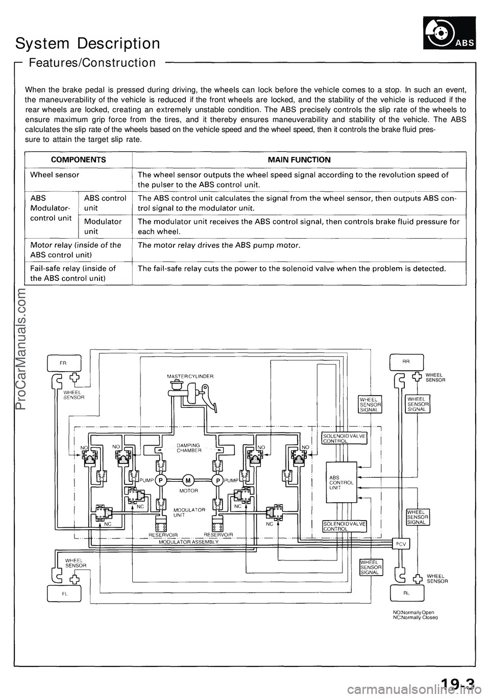
When th e brak e peda l i s presse d durin g driving , th e wheel s ca n loc k befor e th e vehicl e come s t o a stop . I n suc h a n event ,
th e maneuverabilit y o f th e vehicl e i s reduce d i f th e fron t wheel s ar e locked , an d th e stabilit y o f th e vehicl e i s reduce d i f th e
rea r wheel s ar e locked , creatin g a n extremel y unstabl e condition . Th e AB S precisel y control s th e sli p rat e o f th e wheel s t o
ensur e maximu m gri p forc e fro m th e tires , an d i t thereb y ensure s maneuverabilit y an d stabilit y o f th e vehicle . Th e AB S
calculate s th e sli p rat e o f th e wheel s base d o n th e vehicl e spee d an d th e whee l speed , the n it control s th e brak e flui d pres -
sur e t o attai n th e targe t sli p rate .
WHEE L
SENSO R
ProCarManuals.com
Page 252 of 1503
Wheel Alignment
Height
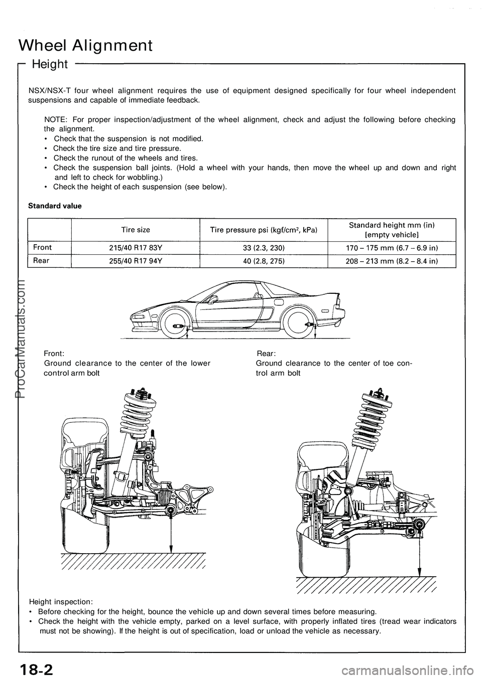
NSX/NSX- T fou r whee l alignmen t require s th e us e o f equipmen t designe d specificall y fo r fou r whee l independen t
suspension s an d capabl e o f immediat e feedback .
NOTE : Fo r prope r inspection/adjustmen t o f th e whee l alignment , chec k an d adjus t th e followin g befor e checkin g
th e alignment .
• Chec k tha t th e suspensio n i s no t modified .
• Chec k th e tir e siz e an d tir e pressure .
• Chec k th e runou t o f th e wheel s an d tires .
• Chec k th e suspensio n bal l joints . (Hol d a whee l wit h you r hands , the n mov e th e whee l u p an d dow n an d righ t
an d lef t t o chec k fo r wobbling. )
• Chec k th e heigh t o f eac h suspensio n (se e below) .
Heigh t inspection :
• Befor e checkin g fo r th e height , bounc e th e vehicl e u p an d dow n severa l time s befor e measuring .
• Chec k th e heigh t wit h th e vehicl e empty , parke d o n a leve l surface , wit h properl y inflate d tire s (trea d wea r indicator s
mus t no t b e showing) . I f th e heigh t i s ou t o f specification , loa d o r unloa d th e vehicl e a s necessary .
Front
: Rear :
Groun d clearanc e t o th e cente r o f th e lowe r Groun d clearanc e t o th e cente r o f toe con -
contro l ar m bol t tro l ar m bol t
ProCarManuals.com
Page 384 of 1503
Towing
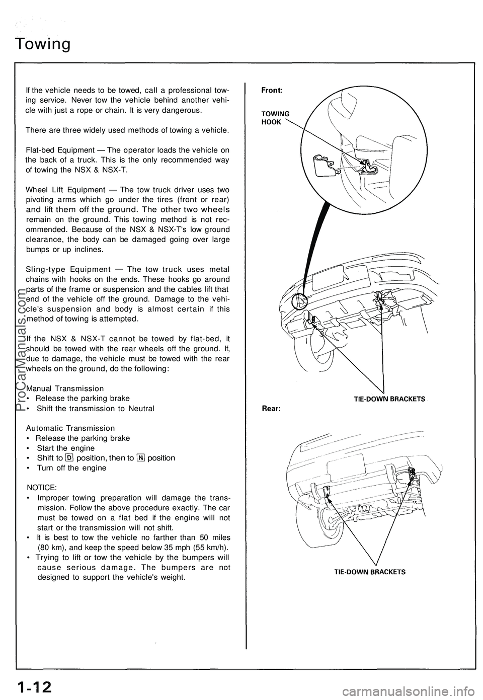
If the vehicle needs to be towed, call a professional tow-
ing service. Never tow the vehicle behind another vehi-
cle with just a rope or chain. It is very dangerous.
There are three widely used methods of towing a vehicle.
Flat-bed Equipment — The operator loads the vehicle on
the back of a truck. This is the only recommended way
of towing the NSX & NSX-T.
Wheel Lift Equipment — The tow truck driver uses two
pivoting arms which go under the tires (front or rear)
and lift them off the ground. The other two wheels
remain on the ground. This towing method is not rec-
ommended. Because of the NSX & NSX-T's low ground
clearance, the body can be damaged going over large
bumps or up inclines.
Sling-type Equipment — The tow truck uses metal
chains with hooks on the ends. These hooks go around
parts of the frame or suspension and the cables lift that
end of the vehicle off the ground. Damage to the vehi-
cle's suspension and body is almost certain if this
method of towing is attempted.
If the NSX & NSX-T cannot be towed by flat-bed, it
should be towed with the rear wheels off the ground. If,
due to damage, the vehicle must be towed with the rear
wheels on the ground, do the following:
Manual Transmission
• Release the parking brake
• Shift the transmission to Neutral
Automatic Transmission
• Release the parking brake
• Start the engine
• Shift to position, then to position
• Turn off the engine
NOTICE:
• Improper towing preparation will damage the trans-
mission. Follow the above procedure exactly. The car
must be towed on a flat bed if the engine will not
start or the transmission will not shift.
• It is best to tow the vehicle no farther than 50 miles
(80 km), and keep the speed below 35 mph (55 km/h).
• Trying to lift or tow the vehicle by the bumpers will
cause serious damage. The bumpers are not
designed to support the vehicle's weight.ProCarManuals.com
Page 385 of 1503
Service Precautions
Handling of Special Nuts and Bolts
Handling of Tires
• The tires on NSX & NSX-T should not be rotated. The
front wheels are 16" in, diameter and the rear wheels
are 17" in, so they cannot be rotated front-to-rear.
The original-equipment tires on NSX & NSX-T have a
unidirectional tread pattern, so they cannot be rotat-
ed side-to-side.
• The folding spare tire cannot be repaired or removed
from the rim.
Engine Steam-cleaning
(NSX-T only)
When steam-cleaning the engine compartment, keep the
roof holder switch dry. If the roof holder switch gets wet
accidentally, dry it thoroughly with compressed air.
Because many sections on this vehicle are constructed
with aluminum alloys, use only the special "Dacro" type
nuts and bolts recommended by Acura.
NOTE:
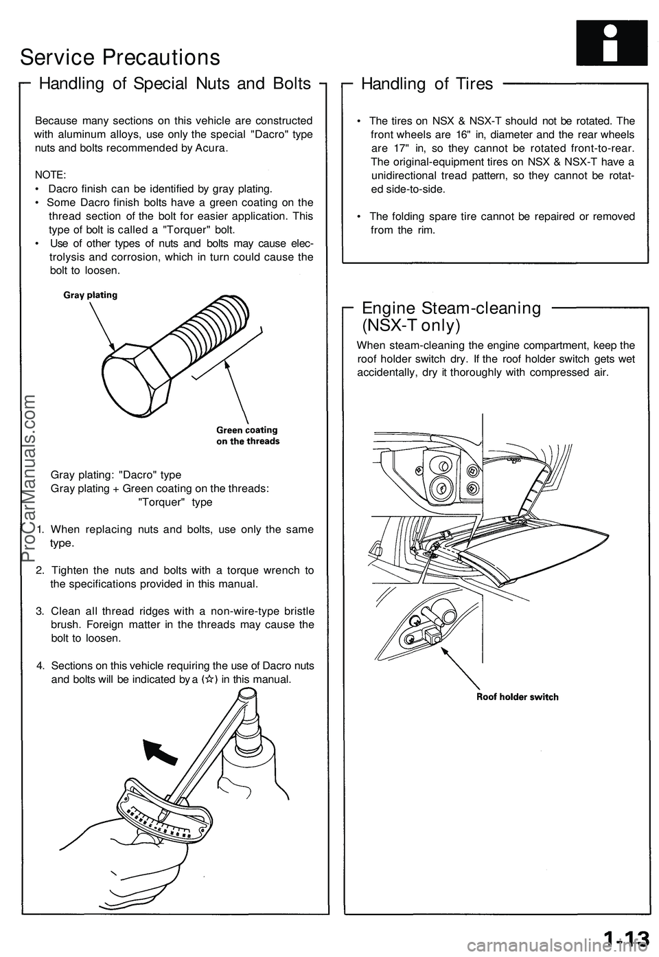
• Dacro finish can be identified by gray plating.
• Some Dacro finish bolts have a green coating on the
thread section of the bolt for easier application. This
type of bolt is called a "Torquer" bolt.
• Use of other types of nuts and bolts may cause elec-
trolysis and corrosion, which in turn could cause the
bolt to loosen.
Gray plating: "Dacro" type
Gray plating + Green coating on the threads:
"Torquer" type
1. When replacing nuts and bolts, use only the same
type.
2. Tighten the nuts and bolts with a torque wrench to
the specifications provided in this manual.
3. Clean all thread ridges with a non-wire-type bristle
brush. Foreign matter in the threads may cause the
bolt to loosen.
4. Sections on this vehicle requiring the use of Dacro nuts
and bolts will be indicated by a in this manual.ProCarManuals.com
Page 937 of 1503
System Description
Suspension Composition
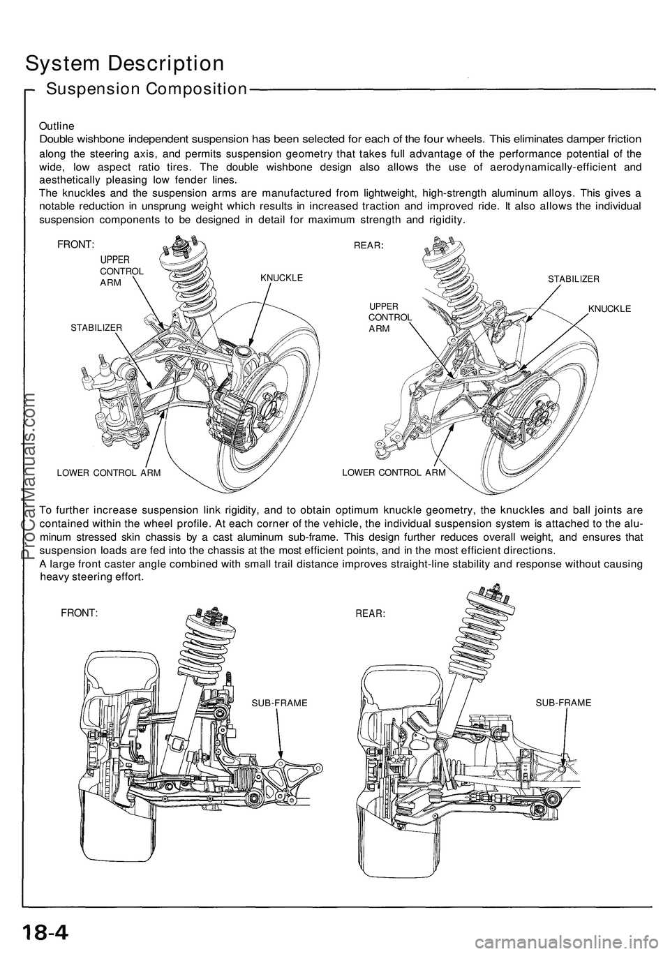
Outline
Double wishbon e independen t suspensio n ha s bee n selecte d fo r eac h o f th e fou r wheels . Thi s eliminate s dampe r frictio n
along th e steerin g axis , an d permit s suspensio n geometr y tha t take s ful l advantag e o f th e performanc e potentia l o f th e
wide , lo w aspec t rati o tires . Th e doubl e wishbon e desig n als o allow s th e us e o f aerodynamically-efficien t an d
aestheticall y pleasin g lo w fende r lines .
Th e knuckle s an d th e suspensio n arm s ar e manufacture d fro m lightweight , high-strengt h aluminu m alloys . Thi s give s a
notabl e reductio n i n unsprun g weigh t whic h result s i n increase d tractio n an d improve d ride . I t als o allow s th e individua l
suspensio n component s t o b e designe d i n detai l fo r maximu m strengt h an d rigidity .
FRONT:
UPPERCONTRO LARMKNUCKL E
STABILIZE R
REAR
STABILIZE R
UPPERCONTRO LARM
LOWE R CONTRO L AR M
KNUCKL E
LOWER CONTRO L AR M
To furthe r increas e suspensio n lin k rigidity , an d t o obtai n optimu m knuckl e geometry , th e knuckle s an d bal l joint s ar e
containe d withi n th e whee l profile . A t eac h corne r o f th e vehicle , th e individua l suspensio n syste m is attache d t o th e alu -
minu m stresse d ski n chassi s b y a cas t aluminu m sub-frame . Thi s desig n furthe r reduce s overal l weight , an d ensure s tha t
suspensio n load s ar e fe d int o th e chassi s a t th e mos t efficien t points , an d i n th e mos t efficien t directions .
A larg e fron t caste r angl e combine d wit h smal l trai l distanc e improve s straight-lin e stabilit y an d respons e withou t causin g
heav y steerin g effort .
FRONT :REAR:
SUB-FRAM ESUB-FRAM E
ProCarManuals.com
Page 939 of 1503
Wheel Alignment
Height
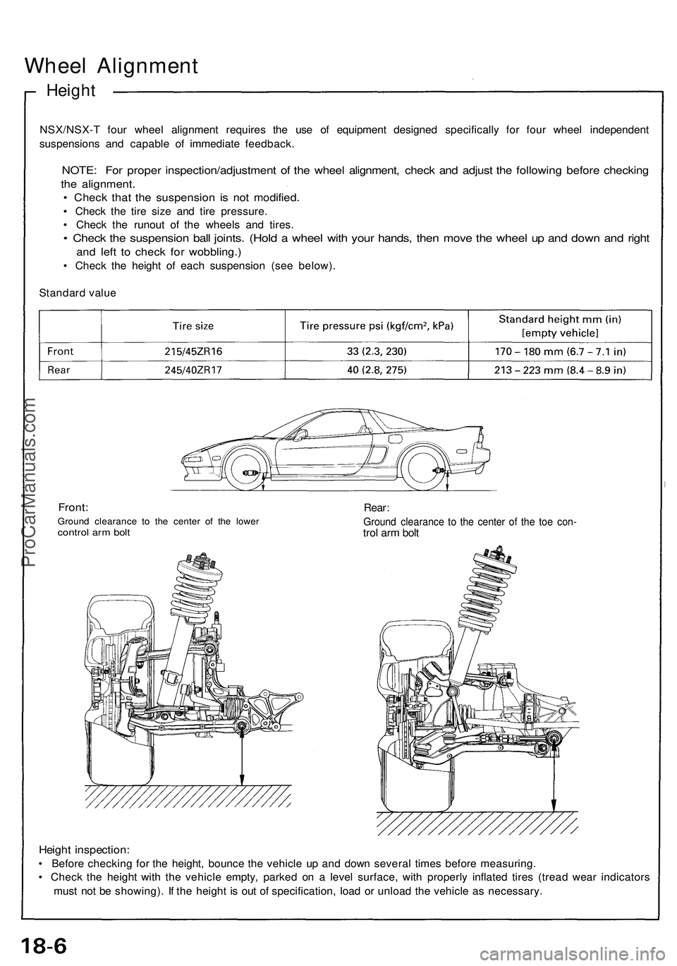
NSX/NSX-T four wheel alignment requires the use of equipment designed specifically for four wheel independent
suspensions and capable of immediate feedback.
NOTE: For proper inspection/adjustment of the wheel alignment, check and adjust the following before checking
the alignment.
• Check that the suspension is not modified.
• Check the tire size and tire pressure.
• Check the runout of the wheels and tires.
• Check the suspension ball joints. (Hold a wheel with your hands, then move the wheel up and down and right
and left to check for wobbling.)
• Check the height of each suspension (see below).
Standard value
Front:
Ground clearance to the center of the lower
control arm bolt
Rear:
Ground clearance to the center of the toe con-
trol arm bolt
Height inspection:
• Before checking for the height, bounce the vehicle up and down several times before measuring.
• Check the height with the vehicle empty, parked on a level surface, with properly inflated tires (tread wear indicators
must not be showing). If the height is out of specification, load or unload the vehicle as necessary.ProCarManuals.com
Page 1018 of 1503
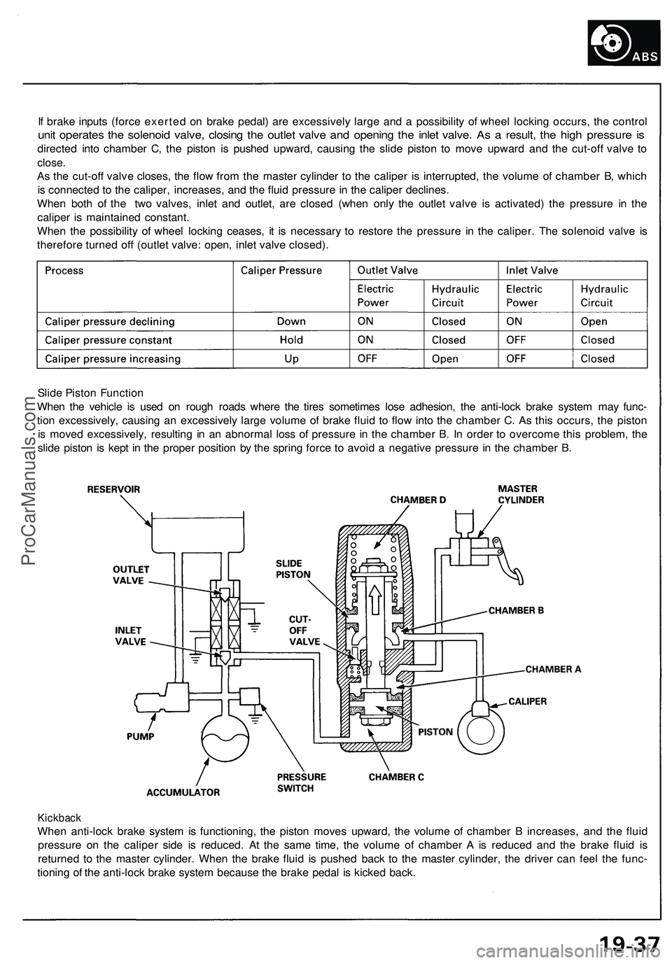
If brake inputs (force exerted on brake pedal) are excessively large and a possibility of wheel locking occurs, the control
unit operates the solenoid valve, closing the outlet valve and opening the inlet valve. As a result, the high pressure is
directed into chamber C, the piston is pushed upward, causing the slide piston to move upward and the cut-off valve to
close.
As the cut-off valve closes, the flow from the master cylinder to the caliper is interrupted, the volume of chamber B, which
is connected to the caliper, increases, and the fluid pressure in the caliper declines.
When both of the two valves, inlet and outlet, are closed (when only the outlet valve is activated) the pressure in the
caliper is maintained constant.
When the possibility of wheel locking ceases, it is necessary to restore the pressure in the caliper. The solenoid valve is
therefore turned off (outlet valve: open, inlet valve closed).
Slide Piston Function
When the vehicle is used on rough roads where the tires sometimes lose adhesion, the anti-lock brake system may func-
tion excessively, causing an excessively large volume of brake fluid to flow into the chamber C. As this occurs, the piston
is moved excessively, resulting in an abnormal loss of pressure in the chamber B. In order to overcome this problem, the
slide piston is kept in the proper position by the spring force to avoid a negative pressure in the chamber B.
Kickback
When anti-lock brake system is functioning, the piston moves upward, the volume of chamber B increases, and the fluid
pressure on the caliper side is reduced. At the same time, the volume of chamber A is reduced and the brake fluid is
returned to the master cylinder. When the brake fluid is pushed back to the master cylinder, the driver can feel the func-
tioning of the anti-lock brake system because the brake pedal is kicked back.ProCarManuals.com
Page 1046 of 1503
Construction and Function
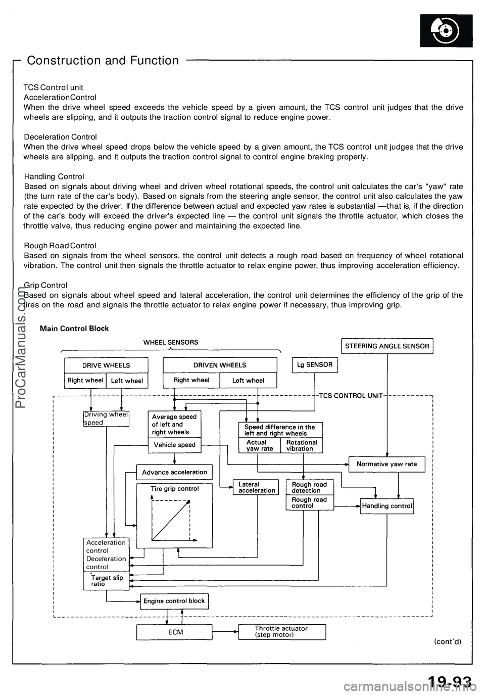
TCS Control unit
Acceleration Control
When the drive wheel speed exceeds the vehicle speed by a given amount, the TCS control unit judges that the drive
wheels are slipping, and it outputs the traction control signal to reduce engine power.
Deceleration Control
When the drive wheel speed drops below the vehicle speed by a given amount, the TCS control unit judges that the drive
wheels are slipping, and it outputs the traction control signal to control engine braking properly.
Handling Control
Based on signals about driving wheel and driven wheel rotational speeds, the control unit calculates the car's "yaw" rate
(the turn rate of the car's body). Based on signals from the steering angle sensor, the control unit also calculates the yaw
rate expected by the driver. If the difference between actual and expected yaw rates is substantial —that is, if the direction
of the car's body will exceed the driver's expected line — the control unit signals the throttle actuator, which closes the
throttle valve, thus reducing engine power and maintaining the expected line.
Rough Road Control
Based on signals from the wheel sensors, the control unit detects a rough road based on frequency of wheel rotational
vibration. The control unit then signals the throttle actuator to relax engine power, thus improving acceleration efficiency.
Grip Control
Based on signals about wheel speed and lateral acceleration, the control unit determines the efficiency of the grip of the
tires on the road and signals the throttle actuator to relax engine power if necessary, thus improving grip.ProCarManuals.com