1997 ACURA NSX length
[x] Cancel search: lengthPage 292 of 1503
Overhaul (Cont'd )
Manual Steerin g
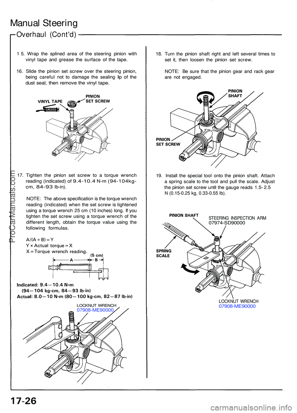
1 5 . Wra p th e spline d are a o f th e steerin g pinio n wit h
viny l tap e an d greas e th e surfac e o f th e tape .
16 . Slid e th e pinio n se t scre w ove r th e steerin g pinion ,
bein g carefu l no t t o damag e th e sealin g li p o f th e
dus t seal , the n remov e th e viny l tape .
18. Tur n th e pinio n shaf t righ t an d lef t severa l time s t o
se t it , the n loose n th e pinio n se t screw .
NOTE : B e sur e tha t th e pinio n gea r an d rac k gea r
ar e no t engaged .
19 . Instal l th e specia l too l ont o th e pinio n shaft . Attac h
a sprin g scal e t o th e too l an d pul l th e scale . Adjus t
th e pinio n se t scre w unti l th e gaug e read s 1. 5- 2. 5
N (0.15-0.25 kg, 0.33-0.55 Ib).
STEERIN G INSPECTIO N AR M07974-SD9000 0
LOCKNUT WRENC H07908-ME9000 0
17. Tighte n th e pinio n se t scre w t o a torqu e wrenc h
readin g (indicated )
of 9.4-10. 4 N-m (94-104kg -
cm, 84-9 3 Ib-in) .
NOTE : Th e abov e specificatio n is th e torqu e wrenc h
readin g (indicated ) whe n th e se t scre w is tightene d
usin g a torqu e wrenc h 2 5 c m (1 0 inches ) long . I f yo u
tighte n th e se t scre w usin g a torqu e wrenc h o f th e
differen t length , obtai n th e torqu e valu e usin g th e
followin g formulas .
LOCKNUT WRENC H07908-ME9000 0
ProCarManuals.com
Page 294 of 1503
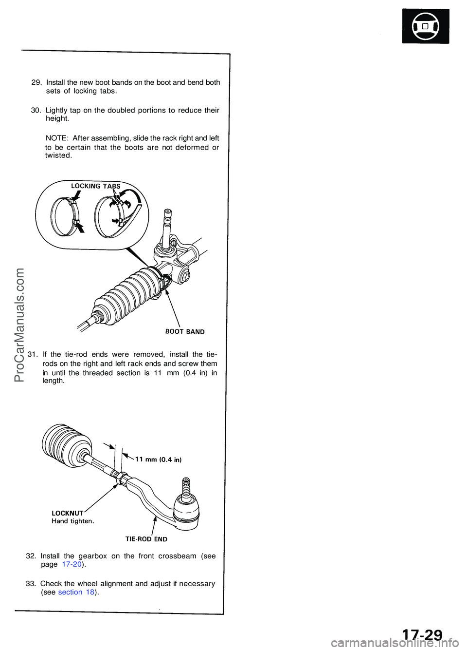
29. Instal l th e ne w boo t band s o n th e boo t an d ben d bot h
set s o f lockin g tabs .
30 . Lightl y ta p o n th e double d portion s t o reduc e thei r
height .
NOTE : Afte r assembling , slid e th e rac k righ t an d lef t
t o b e certai n tha t th e boot s ar e no t deforme d o r
twisted .
32 . Instal l th e gearbo x o n th e fron t crossbea m (se e
pag e 17-20 ).
33 . Chec k th e whee l alignmen t an d adjus t i f necessar y
(se e sectio n 18 ).
31
. I f th e tie-ro d end s wer e removed , instal l th e tie -
rod s o n th e righ t an d lef t rac k end s an d scre w the m
i n unti l th e threade d sectio n i s 1 1 m m (0. 4 in ) i n
length .
ProCarManuals.com
Page 367 of 1503

3-2
Standards and Service Limits
MEASUREMENTSTANDARD (NEW)SERVICE LIMIT
CompressionCheck the engine with the Minimumstarter cranking Maximum variation
kPa (kgf/cm
2, psi)
980 (10.0, 142)
200 (2.0, 28)
Cylinder headWarpage
Height—150.95 – 151.05 (5.943 – 5.947)0.05 (0.002)—
CamshaftEnd play
Camshaft-to-holder oil clearance
Total runout
Cam lobe height M/T IN Primary Mid
Secondary
EX Primary Mid
Secondary
A/T IN Primary Mid
Secondary
EX Primary Mid
Secondary0.05 – 0.15 (0.002 – 0.006)
0.050 – 0.089 (0.002 – 0.004)
0.03 (0.0012) max.
37.086 (1.4601)
38.037 (1.4975)
37.326 (1.4695)
36.559 (1.4393)
37.398 (1.4724)
36.741 (1.4465)
37.266 (1.4672)
37.655 (1.4825)
37.504 (1.4765)
36.559 (1.4393)
37.398 (1.4724)
36.741 (1.4465)0.5 (0.02)
0.15 (0.006)
0.04 (0.0016)
—
—
—
—
—
—
—
—
—
—
—
—
ValveValve clearance IN EX
Valve stem O.D. IN EX
Stem-to-guide clearance IN EX0.15 – 0.19 (0.006 – 0.007)*3
0.17 – 0.21 (0.007 – 0.008)*3
5.475 – 5.485 (0.2156 – 0.2159)
5.45 – 5.46 (0.2146 – 0.2150)
0.025 – 0.055 (0.001 – 0.002)
0.05 – 0.08 (0.002 – 0.003)—
—
5.445 (0.2144)
5.42 (0.2134)
0.08 (0.003)
0.11 (0.004)
Valve seatWidth INEX
Stem installed height IN EX0.80 – 1.00 (0.031 – 0.039)
1.25 – 1.55 (0.049 – 0.061)
41.55 – 42.35 (1.6358 – 1.6673)
41.55 – 42.35 (1.6358 – 1.6673)1.5 (0.059)
2.0 (0.079)
42.435 (1.6707)
42.435 (1.6707)
Valve springFree length M/T IN Outer
Inner
EX
A/T IN EX43.23 (1.7020)*1
43.24 (1.7024)*2
39.79 (1.5665)*1
39.82 (1.5677)*2
46.00 (1.8110)*1
45.98 (1.8102)*2
44.59 (1.7555)*1
44.60 (1.7559)*2
47.40 (1.8661)*1
47.43 (1.8673)*2—
—
—
—
—
—
—
—
—
—
Valve guideI.D. IN and EX
Installed height IN and EX5.51 – 5.53 (0.2169 – 0.2177)
13.75 – 14.25 (0.541 – 0.561)5.53 (0.218)—
Rocker armArm-to-shaft Primary and Secondary IN and EXclearance Mid IN and EX0.025 – 0.052 (0.0010 – 0.0020)
0.024 – 0.053 (0.0009 – 0.0021)0.08 (0.003)
0.08 (0.003)
M/T: Manual Transmission A/T: Automatic Transmission
*1: NIHON HATSUJO made, *2: CHUO HATSUJO made.
*3: Measured between the rocker arm and camshaft.
Cylinder Head/Valve Train — Section 6
*04-NSX (61SW004)SEC03(01-16) 9/22/04 1:48 PM Page 3-2
ProCarManuals.com
Page 368 of 1503
3-13
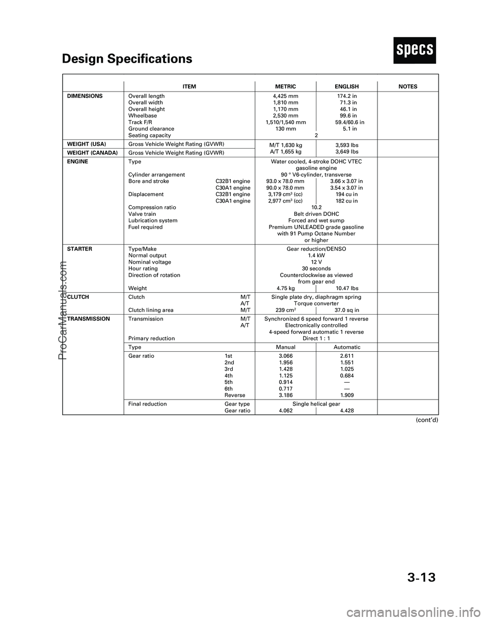
TDesign Specifications
(cont’d)
ITEMMETRICENGLISH
DIMENSIONSOverall length
Overall width
Overall height
Wheelbase
Track F/R
Ground clearance
Seating capacity4,425 mm 174.2 in
1,810 mm 71.3 in
1,170 mm 46.1 in
2,530 mm 99.6 in
1,510/1,540 mm 59.4/60.6 in
130 mm 5.1 in
2
WEIGHT (USA)
Single plate dry, diaphragm spring
Torque converter
239 cm
237.0 sq in
CLUTCHClutch M/T
A/T
Clutch lining area M/T
Gross Vehicle Weight Rating (GVWR)
NOTES
Gear reduction/DENSO
1.4 kW
12 V
30 seconds
Counterclockwise as viewed
from gear end
4.75 kg 10.47 lbs
ENGINEWater cooled, 4-stroke DOHC VTEC
gasoline engine
90 °V6-cylinder, transverse
93.0 x 78.0 mm 3.66 x 3.07 in
90.0 x 78.0 mm 3.54 x 3.07 in
3,179 cm
3(cc) 194 cu in
2,977 cm3(cc) 182 cu in
10.2
Belt driven DOHC
Forced and wet sump
Premium UNLEADED grade gasoline
with 91 Pump Octane Number
or higher
STARTERType/Make
Normal output
Nominal voltage
Hour rating
Direction of rotation
Weight
WEIGHT (CANADA)Gross Vehicle Weight Rating (GVWR)
Synchronized 6 speed forward 1 reverse
Electronically controlled
4-speed forward automatic 1 reverse
Direct 1 : 1Transmission M/T
A/T
Primary reduction
Manual AutomaticType
3.066 2.611
1.956 1.551
1.428 1.025
1.125 0.684
0.914—
0.717—
3.186 1.909Gear ratio 1st
2nd
3rd
4th
5th
6th
Reverse
Single helical gear
4.062 4.428
TRANSMISSION
Final reduction Gear type
Gear ratio
Type
Cylinder arrangement
Bore and strokeC32B1 engine
C30A1 engine
DisplacementC32B1 engine
C30A1 engine
Compression ratio
Valve train
Lubrication system
Fuel required
M/T 1,630 kg 3,593 lbs
A/T 1,655 kg 3,649 lbs
*04-NSX (61SW004)SEC03(01-16) 9/22/04 1:49 PM Page 3-13
ProCarManuals.com
Page 883 of 1503
Driveshafts
Reassembly
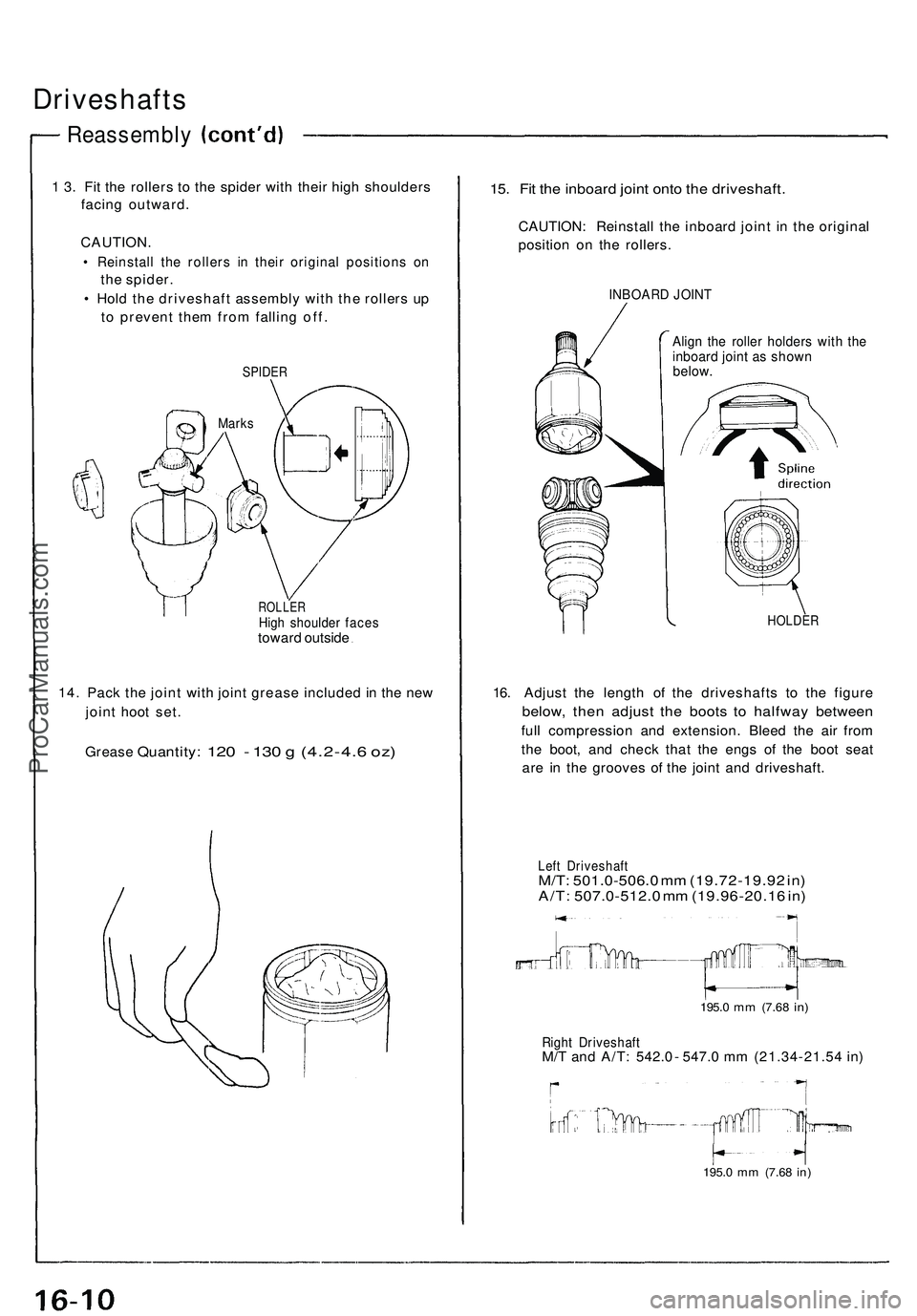
1 3. Fit the rollers to the spider with their high shoulders
facing outward.
CAUTION.
• Reinstall the rollers in their original positions on
the spider.
• Hold the driveshaft assembly with the rollers up
to prevent them from falling off.
SPIDER
ROLLER
High shoulder faces
toward outside
14. Pack the joint with joint grease included in the new
joint hoot set.
Grease
Quantity:
120 - 130 g
(4.2-4.6
oz)
15. Fit the inboard joint onto the driveshaft.
CAUTION: Reinstall the inboard joint in the original
position on the rollers.
INBOARD JOINT
Align the roller holders with the
inboard joint as shown
below.
HOLDER
16. Adjust the length of the driveshafts to the figure
below, then adjust the boots to halfway between
full compression and extension. Bleed the air from
the boot, and check that the engs of the boot seat
are in the grooves of the joint and driveshaft.
Left Driveshaft
M/T: 501.0-506.0 mm (19.72-19.92 in)
A/T: 507.0-512.0 mm (19.96-20.16 in)
195.0
mm
(7.68
in)
Right Driveshaft
M/T and A/T: 542.0 - 547.0 mm (21.34-21.54 in)
195.0
mm
(7.68
in)
MarksProCarManuals.com
Page 932 of 1503
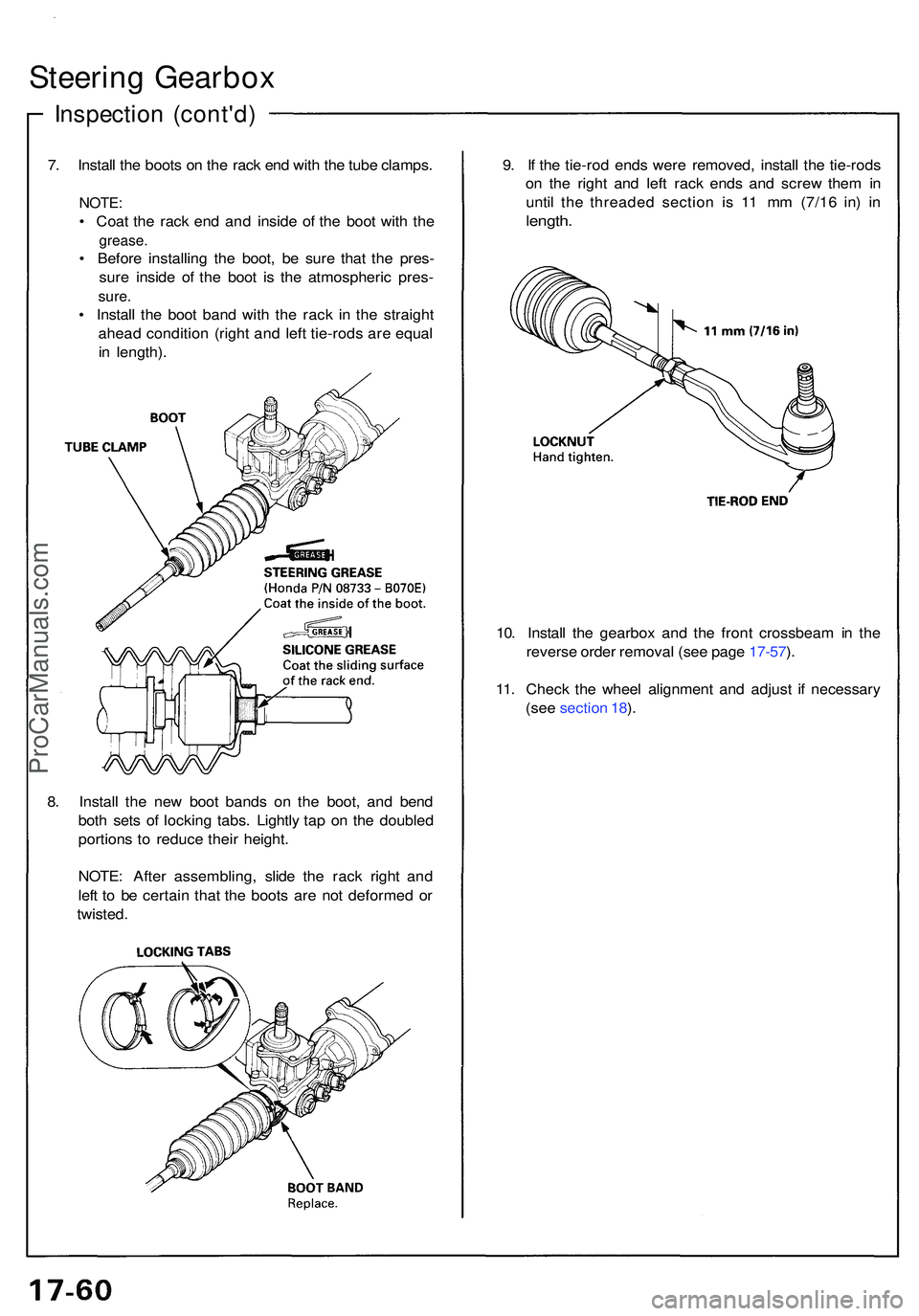
Steering Gearbo x
Inspectio n (cont'd )
7. Instal l th e boot s o n th e rac k en d wit h th e tub e clamps .
NOTE:
• Coa t th e rac k en d an d insid e o f th e boo t wit h th e
grease .
• Befor e installin g th e boot , b e sur e tha t th e pres -
sur e insid e of the boo t i s th e atmospheri c pres -
sure.
• Instal l th e boo t ban d wit h th e rac k i n th e straigh t
ahea d conditio n (righ t an d lef t tie-rod s ar e equa l
i n length) . 9
. I f th e tie-ro d end s wer e removed , instal l th e tie-rod s
o n th e righ t an d lef t rac k end s an d scre w the m in
until the threade d sectio n i s 1 1 m m (7/1 6 in ) i n
length .
10. Instal l th e gearbo x an d th e fron t crossbea m in th e
revers e orde r remova l (se e pag e 17-57 ).
11 . Chec k th e whee l alignmen t an d adjus t i f necessar y
(se e sectio n 18 ).
8 . Instal l th e ne w boo t band s o n th e boot , an d ben d
bot h set s o f lockin g tabs . Lightl y ta p o n th e double d
portion s t o reduc e thei r height .
NOTE : Afte r assembling , slid e th e rac k righ t an d
lef t t o b e certai n tha t th e boot s ar e no t deforme d o r
twisted .
ProCarManuals.com
Page 945 of 1503
Wheel Alignmen t
Rear Whee l Alignmen t Adjustin g Procedur e
NOTE: NSX/NSX- T fou r whee l alignmen t require s th e
us e o f equipmen t designe d specificall y fo r fou r whee l
independen t suspension s an d capabl e o f immediat e
feedback.
1. Driv e th e vehicl e o n th e alignmen t rack .
2 . Chec k th e tir e pressur e an d rid e heigh t a s describe d
o n pag e 18-6 .
3 . Cente r th e steerin g wheel .
Toe
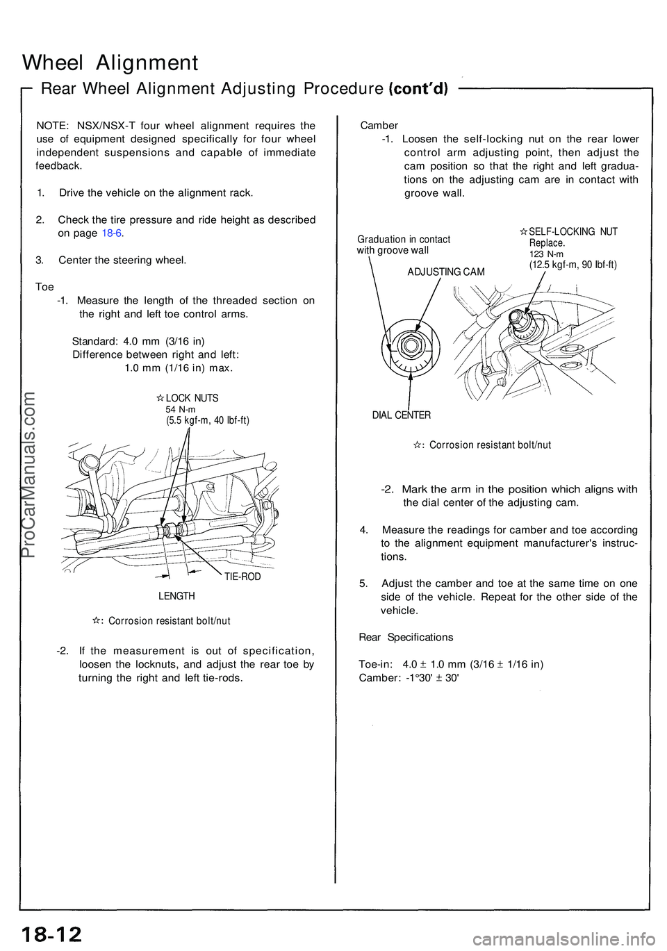
-1. Measur e th e lengt h o f th e threade d sectio n o n
th e righ t an d lef t to e contro l arms .
Standard : 4. 0 m m (3/1 6 in )
Differenc e betwee n righ t an d left :
1.0 m m (1/1 6 in) max .
LOCK NUT S54 N- m(5.5 kgf-m , 4 0 Ibf-ft )
TIE-RO D
LENGTH
Corrosio n resistan t bolt/nu t
-2. I f th e measuremen t i s ou t o f specification ,
loose n th e locknuts , an d adjus t th e rea r to e b y
turnin g th e righ t an d lef t tie-rods .
Camber
-1. Loose n th e self-lockin g nu t o n th e rea r lowe r
contro l ar m adjustin g point , the n adjus t th e
ca m positio n s o tha t th e righ t an d lef t gradua -
tion s o n th e adjustin g ca m ar e i n contac t wit h
groov e wall .
Graduatio n i n contac twith groov e wal l
SELF-LOCKIN G NU TReplace .123 N- m(12. 5 kgf-m , 9 0 Ibf-ft )
DIAL CENTE R
Corrosio n resistan t bolt/nu t
-2. Mar k th e ar m in th e positio n whic h align s wit h
the dia l cente r o f th e adjustin g cam .
4 . Measur e th e reading s fo r cambe r an d to e accordin g
t o th e alignmen t equipmen t manufacturer' s instruc -
tions .
5 . Adjus t th e cambe r an d to e a t th e sam e tim e o n on e
sid e o f th e vehicle . Repea t fo r th e othe r sid e o f th e
vehicle .
Rea r Specification s
Toe-in: 4. 0 1. 0 m m (3/1 6 1/1 6 in )
Camber : -1°30 ' 30 '
ADJUSTIN G CA M
ProCarManuals.com
Page 1143 of 1503
Roof
Roof Sid e Seal/Retaine r Replacemen t (cont'd )
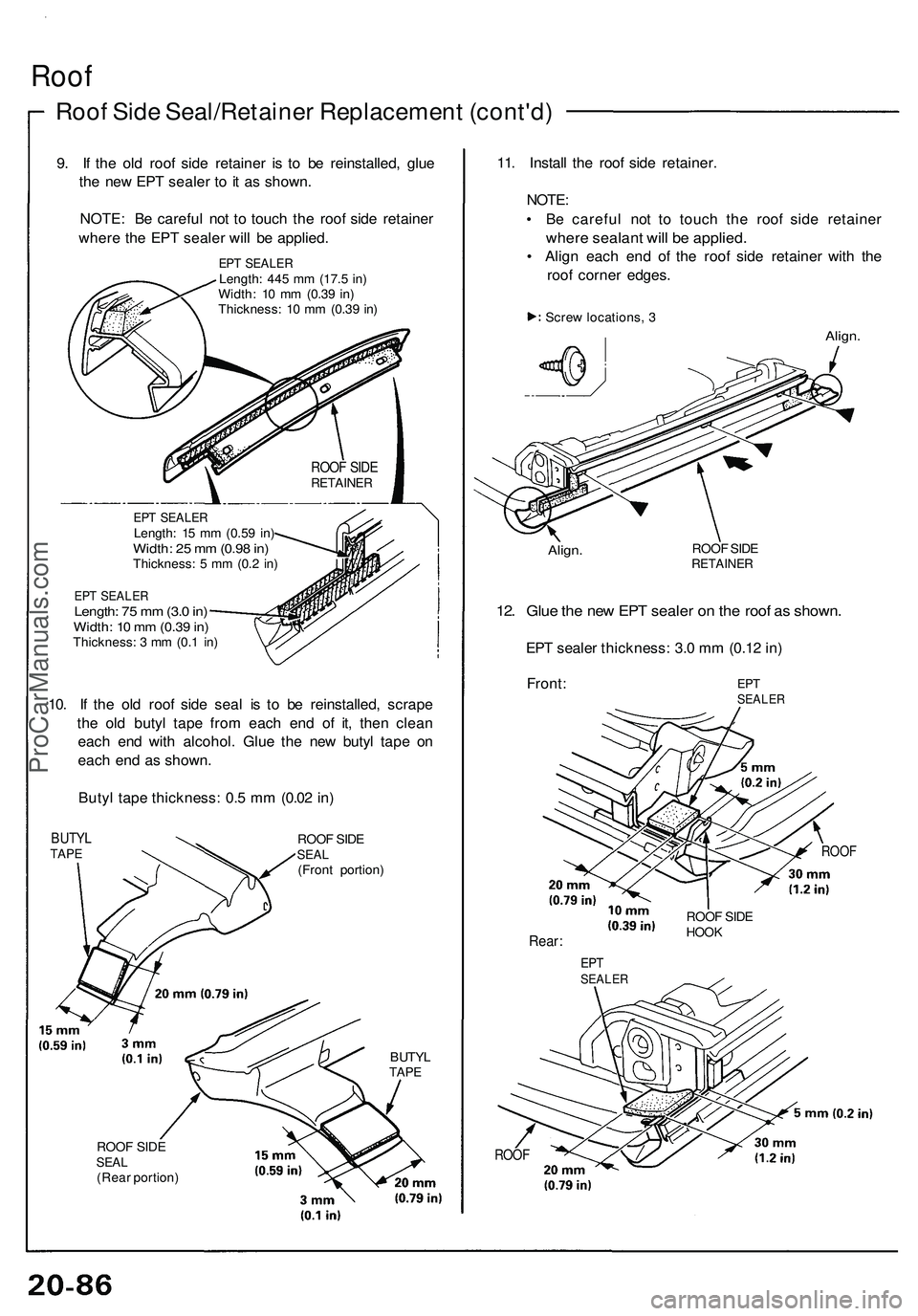
9. I f th e ol d roo f sid e retaine r i s t o b e reinstalled , glu e
th e ne w EP T seale r t o it a s shown .
NOTE : B e carefu l no t t o touc h th e roo f sid e retaine r
wher e th e EP T seale r wil l b e applied .
EPT SEALE RLength: 44 5 m m (17. 5 in )
Width : 1 0 m m (0.3 9 in )
Thickness : 1 0 m m (0.3 9 in )
EP T SEALE RLength: 1 5 m m (0.5 9 in )Width : 2 5 m m (0.9 8 in )Thickness : 5 m m (0. 2 in )
EP T SEALE RLength: 7 5 m m (3. 0 in )Width : 1 0 m m (0.3 9 in )Thickness : 3 m m (0. 1 in )
10. I f th e ol d roo f sid e sea l i s t o b e reinstalled , scrap e
th e ol d buty l tap e fro m eac h en d of it, the n clea n
eac h en d wit h alcohol . Glu e th e ne w buty l tap e o n
eac h en d a s shown .
Buty l tap e thickness : 0. 5 m m (0.0 2 in )
BUTY LTAPEROO F SID ESEA L(Fron t portion )
BUTYLTAPE
ROO F SID ESEA L(Rea r portion )
11. Instal l th e roo f sid e retainer .
NOTE :
• B e carefu l no t t o touc h th e roo f sid e retaine r
where sealan t wil l b e applied .
• Alig n eac h en d o f th e roo f sid e retaine r wit h th e
roo f corne r edges .
Screw locations , 3
Align .
Align.ROOF SID ERETAINE R
12. Glu e th e ne w EP T seale r o n th e roo f a s shown .
EPT seale r thickness : 3. 0 m m (0.1 2 in )
Front :
ROOF
Rear :
ROOF
ROOF SID ERETAINE R
EPTSEALE R
ROOF SID EHOO K
EPTSEALE R
ProCarManuals.com