1997 ACURA NSX height
[x] Cancel search: heightPage 252 of 1503
Wheel Alignment
Height
NSX/NSX- T fou r whee l alignmen t require s th e us e o f equipmen t designe d specificall y fo r fou r whee l independen t
suspension s an d capabl e o f immediat e feedback .
NOTE : Fo r prope r inspection/adjustmen t o f th e whee l alignment , chec k an d adjus t th e followin g befor e checkin g
th e alignment .
• Chec k tha t th e suspensio n i s no t modified .
• Chec k th e tir e siz e an d tir e pressure .
• Chec k th e runou t o f th e wheel s an d tires .
• Chec k th e suspensio n bal l joints . (Hol d a whee l wit h you r hands , the n mov e th e whee l u p an d dow n an d righ t
an d lef t t o chec k fo r wobbling. )
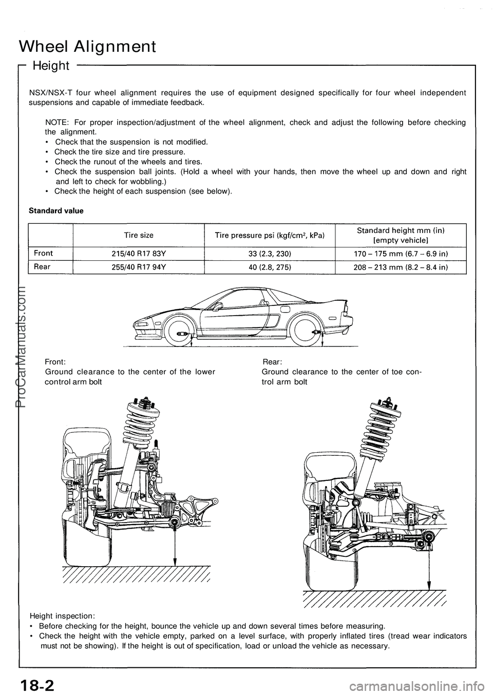
• Chec k th e heigh t o f eac h suspensio n (se e below) .
Heigh t inspection :
• Befor e checkin g fo r th e height , bounc e th e vehicl e u p an d dow n severa l time s befor e measuring .
• Chec k th e heigh t wit h th e vehicl e empty , parke d o n a leve l surface , wit h properl y inflate d tire s (trea d wea r indicator s
mus t no t b e showing) . I f th e heigh t i s ou t o f specification , loa d o r unloa d th e vehicl e a s necessary .
Front
: Rear :
Groun d clearanc e t o th e cente r o f th e lowe r Groun d clearanc e t o th e cente r o f toe con -
contro l ar m bol t tro l ar m bol t
ProCarManuals.com
Page 275 of 1503
Headlights
Adjustmen t
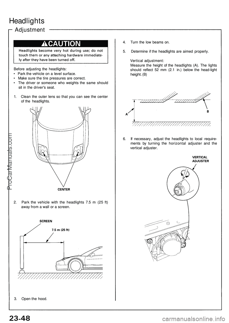
Before adjustin g th e headlights :
• Par k th e vehicl e o n a leve l surface .
• Mak e sur e th e tir e pressure s ar e correct .
• Th e drive r o r someon e wh o weight s th e sam e shoul d
si t i n th e driver' s seat .
1 . Clea n th e oute r len s s o tha t yo u ca n se e th e cente r
o f th e headlights . 4
. Tur n th e lo w beam s on .
5 . Determin e i f th e headlight s ar e aime d properly .
Vertica l adjustment :
Measur e th e heigh t o f th e headlight s (A) . Th e light s
shoul d reflec t 5 2 m m (2. 1 in. ) belo w th e head-ligh t
height. (B)
6. I f necessary , adjus t th e headlight s t o loca l require -
ment s b y turnin g th e horizonta l adjuste r an d th e
vertica l adjuster .
2 . Par k th e vehicl e wit h th e headlight s 7. 5 m (2 5 ft )
awa y fro m a wal l o r a screen .
3 . Ope n th e hood .
ProCarManuals.com
Page 294 of 1503
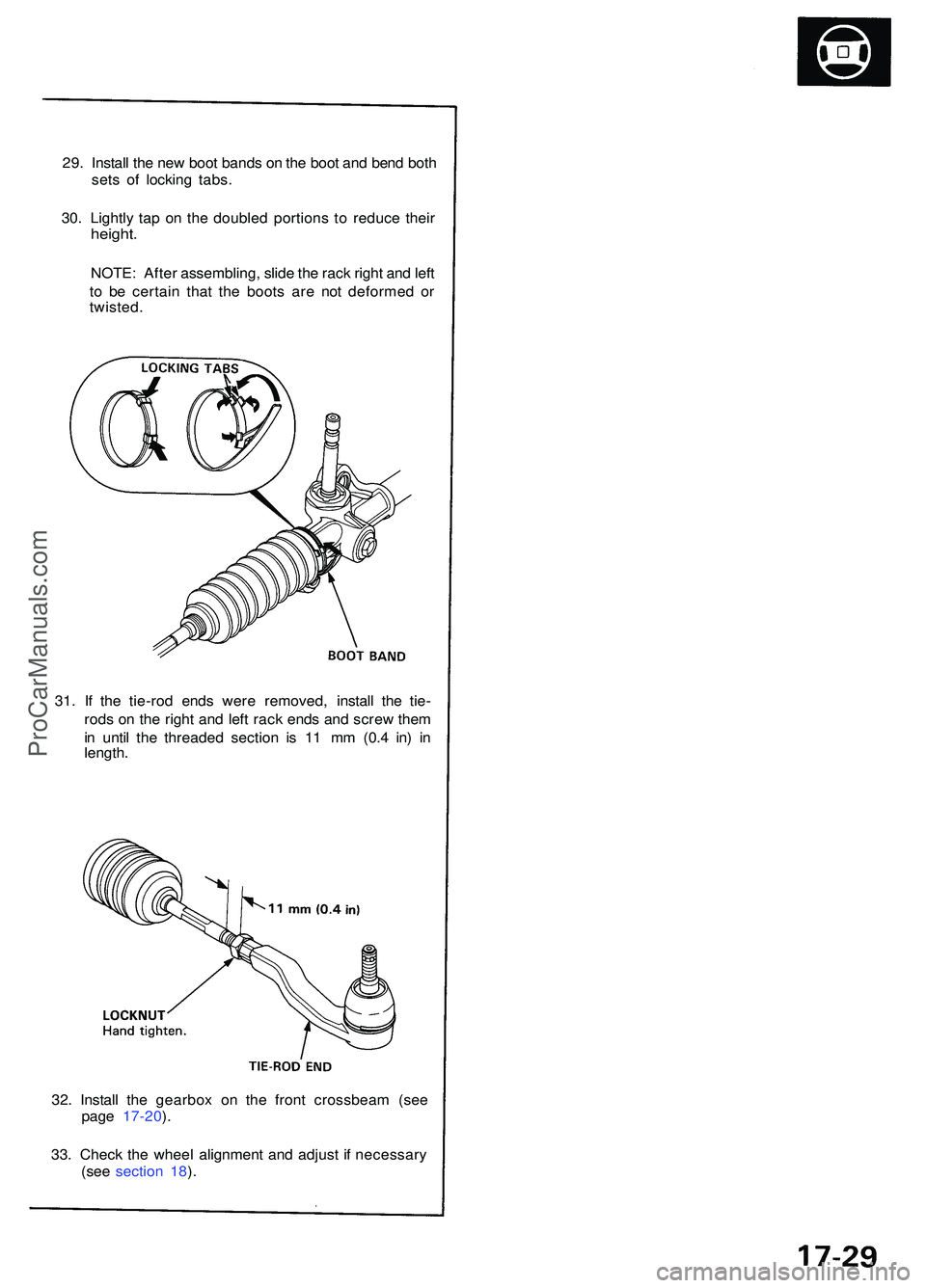
29. Instal l th e ne w boo t band s o n th e boo t an d ben d bot h
set s o f lockin g tabs .
30 . Lightl y ta p o n th e double d portion s t o reduc e thei r
height .
NOTE : Afte r assembling , slid e th e rac k righ t an d lef t
t o b e certai n tha t th e boot s ar e no t deforme d o r
twisted .
32 . Instal l th e gearbo x o n th e fron t crossbea m (se e
pag e 17-20 ).
33 . Chec k th e whee l alignmen t an d adjus t i f necessar y
(se e sectio n 18 ).
31
. I f th e tie-ro d end s wer e removed , instal l th e tie -
rod s o n th e righ t an d lef t rac k end s an d scre w the m
i n unti l th e threade d sectio n i s 1 1 m m (0. 4 in ) i n
length .
ProCarManuals.com
Page 367 of 1503

3-2
Standards and Service Limits
MEASUREMENTSTANDARD (NEW)SERVICE LIMIT
CompressionCheck the engine with the Minimumstarter cranking Maximum variation
kPa (kgf/cm
2, psi)
980 (10.0, 142)
200 (2.0, 28)
Cylinder headWarpage
Height—150.95 – 151.05 (5.943 – 5.947)0.05 (0.002)—
CamshaftEnd play
Camshaft-to-holder oil clearance
Total runout
Cam lobe height M/T IN Primary Mid
Secondary
EX Primary Mid
Secondary
A/T IN Primary Mid
Secondary
EX Primary Mid
Secondary0.05 – 0.15 (0.002 – 0.006)
0.050 – 0.089 (0.002 – 0.004)
0.03 (0.0012) max.
37.086 (1.4601)
38.037 (1.4975)
37.326 (1.4695)
36.559 (1.4393)
37.398 (1.4724)
36.741 (1.4465)
37.266 (1.4672)
37.655 (1.4825)
37.504 (1.4765)
36.559 (1.4393)
37.398 (1.4724)
36.741 (1.4465)0.5 (0.02)
0.15 (0.006)
0.04 (0.0016)
—
—
—
—
—
—
—
—
—
—
—
—
ValveValve clearance IN EX
Valve stem O.D. IN EX
Stem-to-guide clearance IN EX0.15 – 0.19 (0.006 – 0.007)*3
0.17 – 0.21 (0.007 – 0.008)*3
5.475 – 5.485 (0.2156 – 0.2159)
5.45 – 5.46 (0.2146 – 0.2150)
0.025 – 0.055 (0.001 – 0.002)
0.05 – 0.08 (0.002 – 0.003)—
—
5.445 (0.2144)
5.42 (0.2134)
0.08 (0.003)
0.11 (0.004)
Valve seatWidth INEX
Stem installed height IN EX0.80 – 1.00 (0.031 – 0.039)
1.25 – 1.55 (0.049 – 0.061)
41.55 – 42.35 (1.6358 – 1.6673)
41.55 – 42.35 (1.6358 – 1.6673)1.5 (0.059)
2.0 (0.079)
42.435 (1.6707)
42.435 (1.6707)
Valve springFree length M/T IN Outer
Inner
EX
A/T IN EX43.23 (1.7020)*1
43.24 (1.7024)*2
39.79 (1.5665)*1
39.82 (1.5677)*2
46.00 (1.8110)*1
45.98 (1.8102)*2
44.59 (1.7555)*1
44.60 (1.7559)*2
47.40 (1.8661)*1
47.43 (1.8673)*2—
—
—
—
—
—
—
—
—
—
Valve guideI.D. IN and EX
Installed height IN and EX5.51 – 5.53 (0.2169 – 0.2177)
13.75 – 14.25 (0.541 – 0.561)5.53 (0.218)—
Rocker armArm-to-shaft Primary and Secondary IN and EXclearance Mid IN and EX0.025 – 0.052 (0.0010 – 0.0020)
0.024 – 0.053 (0.0009 – 0.0021)0.08 (0.003)
0.08 (0.003)
M/T: Manual Transmission A/T: Automatic Transmission
*1: NIHON HATSUJO made, *2: CHUO HATSUJO made.
*3: Measured between the rocker arm and camshaft.
Cylinder Head/Valve Train — Section 6
*04-NSX (61SW004)SEC03(01-16) 9/22/04 1:48 PM Page 3-2
ProCarManuals.com
Page 368 of 1503
3-13
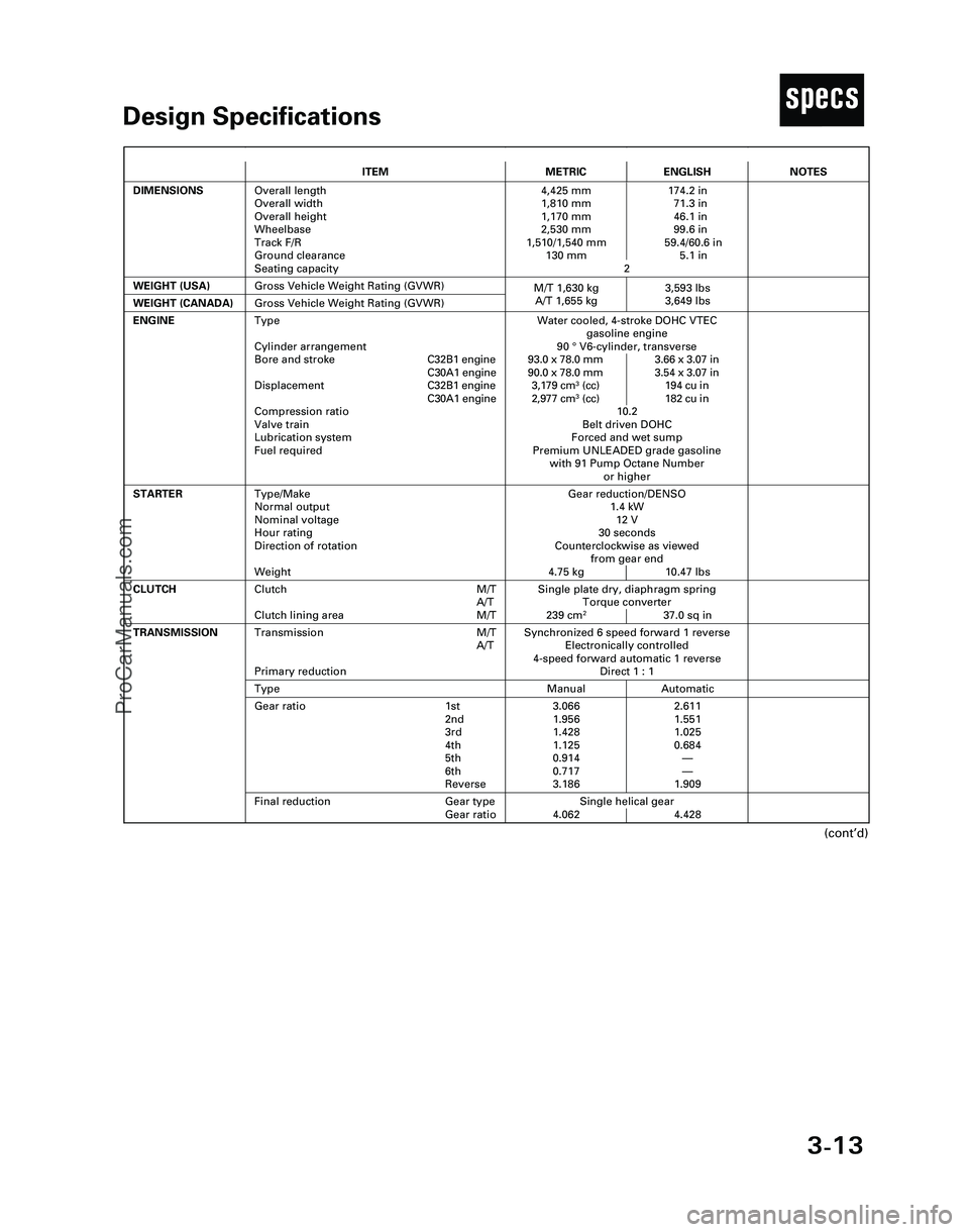
TDesign Specifications
(cont’d)
ITEMMETRICENGLISH
DIMENSIONSOverall length
Overall width
Overall height
Wheelbase
Track F/R
Ground clearance
Seating capacity4,425 mm 174.2 in
1,810 mm 71.3 in
1,170 mm 46.1 in
2,530 mm 99.6 in
1,510/1,540 mm 59.4/60.6 in
130 mm 5.1 in
2
WEIGHT (USA)
Single plate dry, diaphragm spring
Torque converter
239 cm
237.0 sq in
CLUTCHClutch M/T
A/T
Clutch lining area M/T
Gross Vehicle Weight Rating (GVWR)
NOTES
Gear reduction/DENSO
1.4 kW
12 V
30 seconds
Counterclockwise as viewed
from gear end
4.75 kg 10.47 lbs
ENGINEWater cooled, 4-stroke DOHC VTEC
gasoline engine
90 °V6-cylinder, transverse
93.0 x 78.0 mm 3.66 x 3.07 in
90.0 x 78.0 mm 3.54 x 3.07 in
3,179 cm
3(cc) 194 cu in
2,977 cm3(cc) 182 cu in
10.2
Belt driven DOHC
Forced and wet sump
Premium UNLEADED grade gasoline
with 91 Pump Octane Number
or higher
STARTERType/Make
Normal output
Nominal voltage
Hour rating
Direction of rotation
Weight
WEIGHT (CANADA)Gross Vehicle Weight Rating (GVWR)
Synchronized 6 speed forward 1 reverse
Electronically controlled
4-speed forward automatic 1 reverse
Direct 1 : 1Transmission M/T
A/T
Primary reduction
Manual AutomaticType
3.066 2.611
1.956 1.551
1.428 1.025
1.125 0.684
0.914—
0.717—
3.186 1.909Gear ratio 1st
2nd
3rd
4th
5th
6th
Reverse
Single helical gear
4.062 4.428
TRANSMISSION
Final reduction Gear type
Gear ratio
Type
Cylinder arrangement
Bore and strokeC32B1 engine
C30A1 engine
DisplacementC32B1 engine
C30A1 engine
Compression ratio
Valve train
Lubrication system
Fuel required
M/T 1,630 kg 3,593 lbs
A/T 1,655 kg 3,649 lbs
*04-NSX (61SW004)SEC03(01-16) 9/22/04 1:49 PM Page 3-13
ProCarManuals.com
Page 382 of 1503
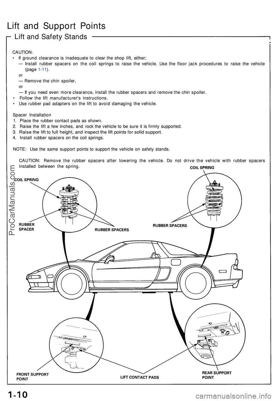
Lift an d Suppor t Point s
Lift an d Safet y Stand s
CAUTION :
• I f groun d clearanc e i s inadequat e t o clea r th e sho p lift , either ;
— Instal l rubbe r spacer s o n th e coi l spring s t o rais e th e vehicle . Us e th e floo r jac k procedure s t o rais e th e vehicl e
(pag e 1-11 ).
o r
— Remov e th e chi n spoiler ,
or
— If yo u nee d eve n mor e clearance , instal l th e rubbe r spacer s an d remov e th e chi n spoiler .
• Follo w th e lif t manufacturer' s instructions .
• Us e rubbe r pa d adapter s o n th e lif t t o avoi d damagin g th e vehicle .
Space r Installatio n
1 . Plac e th e rubbe r contac t pad s a s shown .
2 . Rais e th e lif t a fe w inches , an d roc k th e vehicl e t o b e sur e i t i s firml y supported .
3. Rais e th e lif t t o ful l height , an d inspec t th e lif t point s fo r soli d support .
4. Instal l rubbe r spacer s o n th e coi l springs .
NOTE : Us e th e sam e suppor t point s t o suppor t th e vehicl e o n safet y stands .
CAUTION : Remov e th e rubbe r spacer s afte r lowerin g th e vehicle . D o no t driv e th e vehicl e wit h rubbe r spacer s
installe d betwee n th e spring .
ProCarManuals.com
Page 411 of 1503
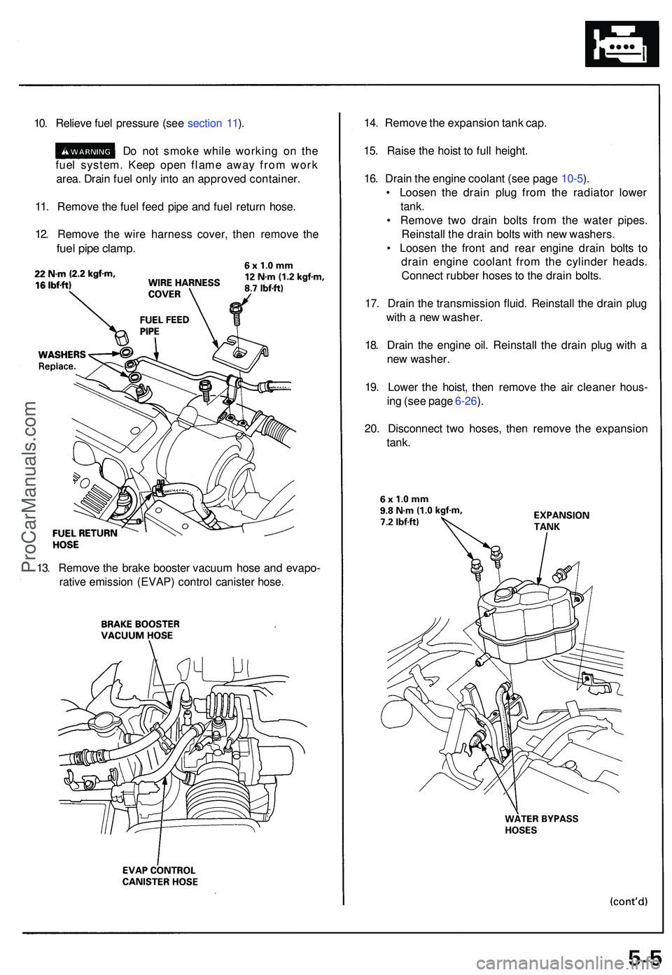
10. Reliev e fue l pressur e (se e sectio n 11 ).
D o no t smok e whil e workin g o n th e
fue l system . Kee p ope n flam e awa y fro m wor k
area . Drai n fue l onl y int o a n approve d container .
11 . Remov e th e fue l fee d pip e an d fue l retur n hose .
12 . Remov e th e wir e harnes s cover , the n remov e th e
fue l pip e clamp .
14. Remov e th e expansio n tan k cap .
15 . Rais e th e hois t t o ful l height .
16 . Drai n th e engin e coolan t (se e pag e 10-5 ).
• Loose n th e drai n plu g fro m th e radiato r lowe r
tank.
• Remov e tw o drai n bolt s fro m th e wate r pipes .
Reinstal l th e drai n bolt s wit h ne w washers .
• Loose n th e fron t an d rea r engin e drai n bolt s t o
drai n engin e coolan t fro m th e cylinde r heads .
Connec t rubbe r hose s t o th e drai n bolts .
17 . Drai n th e transmissio n fluid . Reinstal l th e drai n plu g
wit h a ne w washer .
18 . Drai n th e engin e oil . Reinstal l th e drai n plu g wit h a
ne w washer .
19 . Lowe r th e hoist , the n remov e th e ai r cleane r hous -
in g (se e pag e 6-26 ).
20 . Disconnec t tw o hoses , the n remov e th e expansio n
tank.
13. Remov e th e brak e booste r vacuu m hos e an d evapo -
rativ e emissio n (EVAP ) contro l caniste r hose .
ProCarManuals.com
Page 413 of 1503
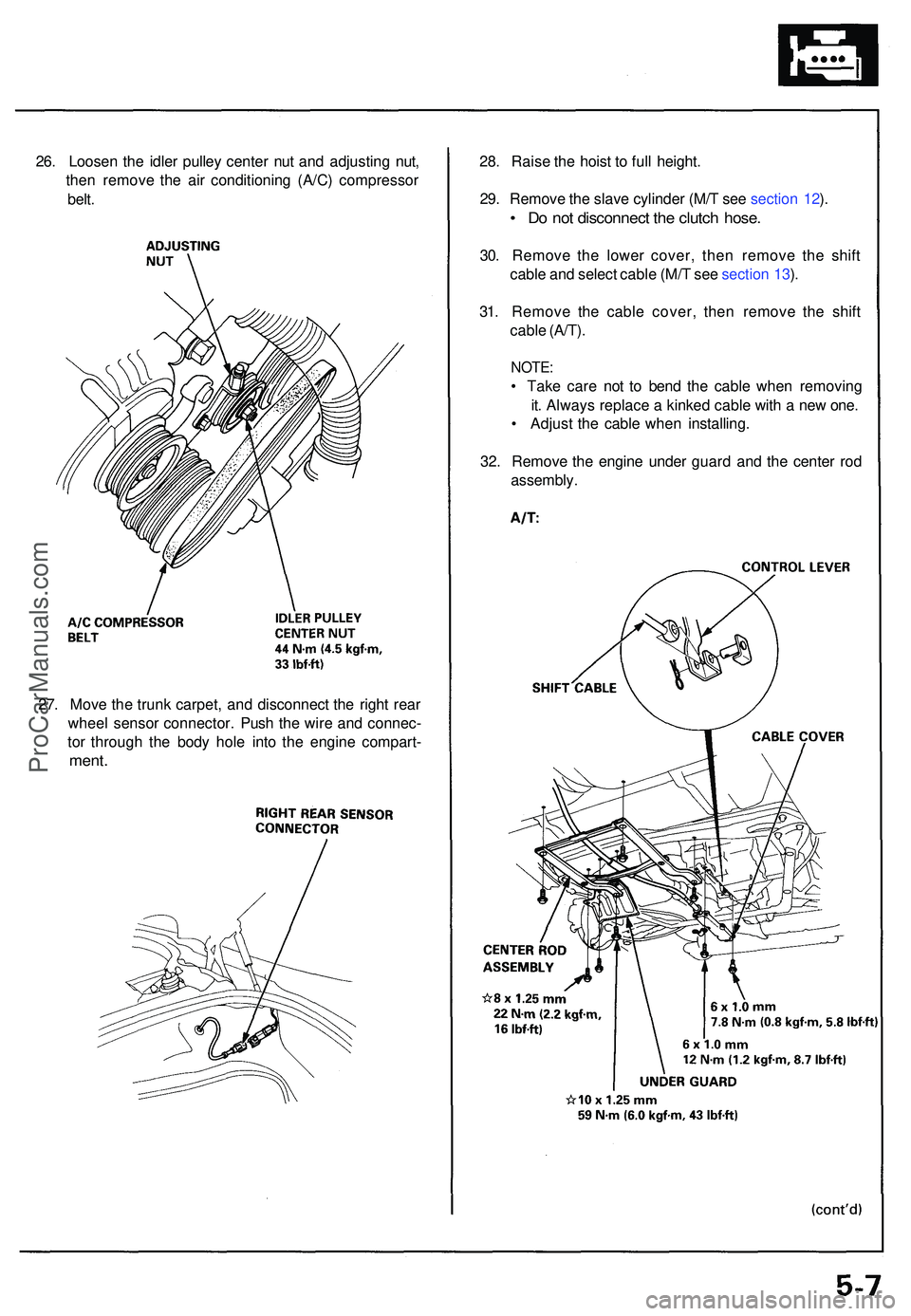
26. Loose n th e idle r pulle y cente r nu t an d adjustin g nut ,
the n remov e th e ai r conditionin g (A/C ) compresso r
belt . 28
. Rais e th e hois t t o ful l height .
29 . Remov e th e slav e cylinde r (M/ T se e sectio n 12 ).
• D o no t disconnec t th e clutc h hose .
30. Remov e th e lowe r cover , the n remov e th e shif t
cabl e an d selec t cabl e (M/ T se e sectio n 13 ).
31 . Remov e th e cabl e cover , the n remov e th e shif t
cabl e (A/T) .
NOTE :
• Tak e car e no t t o ben d th e cabl e whe n removin g
it . Alway s replac e a kinke d cabl e wit h a ne w one .
• Adjus t th e cabl e whe n installing .
32 . Remov e th e engin e unde r guar d an d th e cente r ro d
assembly .
27 . Mov e th e trun k carpet , an d disconnec t th e righ t rea r
whee l senso r connector . Pus h th e wir e an d connec -
to r throug h th e bod y hol e int o th e engin e compart -
ment.
ProCarManuals.com