Page 938 of 1503

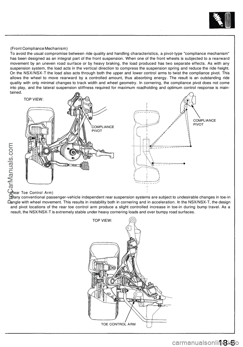
(Front Compliance Mechanism)
To avoid the usual compromise between ride quality and handling characteristics, a pivot-type "compliance mechanism"
has been designed as an integral part of the front suspension. When one of the front wheels is subjected to a rearward
movement by an uneven road surface or by heavy braking, the load produced has two separate effects. As with any
suspension system, the load acts in the vertical direction to compress the suspension spring and reduce the ride height.
On the NSX/NSX-T the load also acts through both the upper and lower control arms to twist the compliance pivot. This
allows the wheel to move rearward by a controlled amount, thus absorbing energy. The result is an outstanding ride
quality with only minimal changes to track width and wheel geometry. In cornering, the compliance pivot does not come
into play, and the lateral suspension stiffness required for maximum roadholding and optimum control response is main-
tained.
TOP VIEW:
(Rear Toe Control Arm)
Many conventional passenger-vehicle independent rear suspension systems are subject to undesirable changes in toe-in
angle with wheel movement. This results in instability both in cornering and in acceleration. In the NSX/NSX-T, the design
and pivot locations of the rear toe control arm produce a slight controlled increase in toe-in during bump travel. As a
result, the NSX/NSX-T is extremely stable under heavy cornering loads and over bumpy road surfaces.
TOP VIEW:
TOE CONTROL ARM
COMPLIANCE
PIVOT
COMPLIANCE
PIVOTProCarManuals.com
Page 939 of 1503

Wheel Alignment
Height
NSX/NSX-T four wheel alignment requires the use of equipment designed specifically for four wheel independent
suspensions and capable of immediate feedback.
NOTE: For proper inspection/adjustment of the wheel alignment, check and adjust the following before checking
the alignment.
• Check that the suspension is not modified.
• Check the tire size and tire pressure.
• Check the runout of the wheels and tires.
• Check the suspension ball joints. (Hold a wheel with your hands, then move the wheel up and down and right
and left to check for wobbling.)
• Check the height of each suspension (see below).
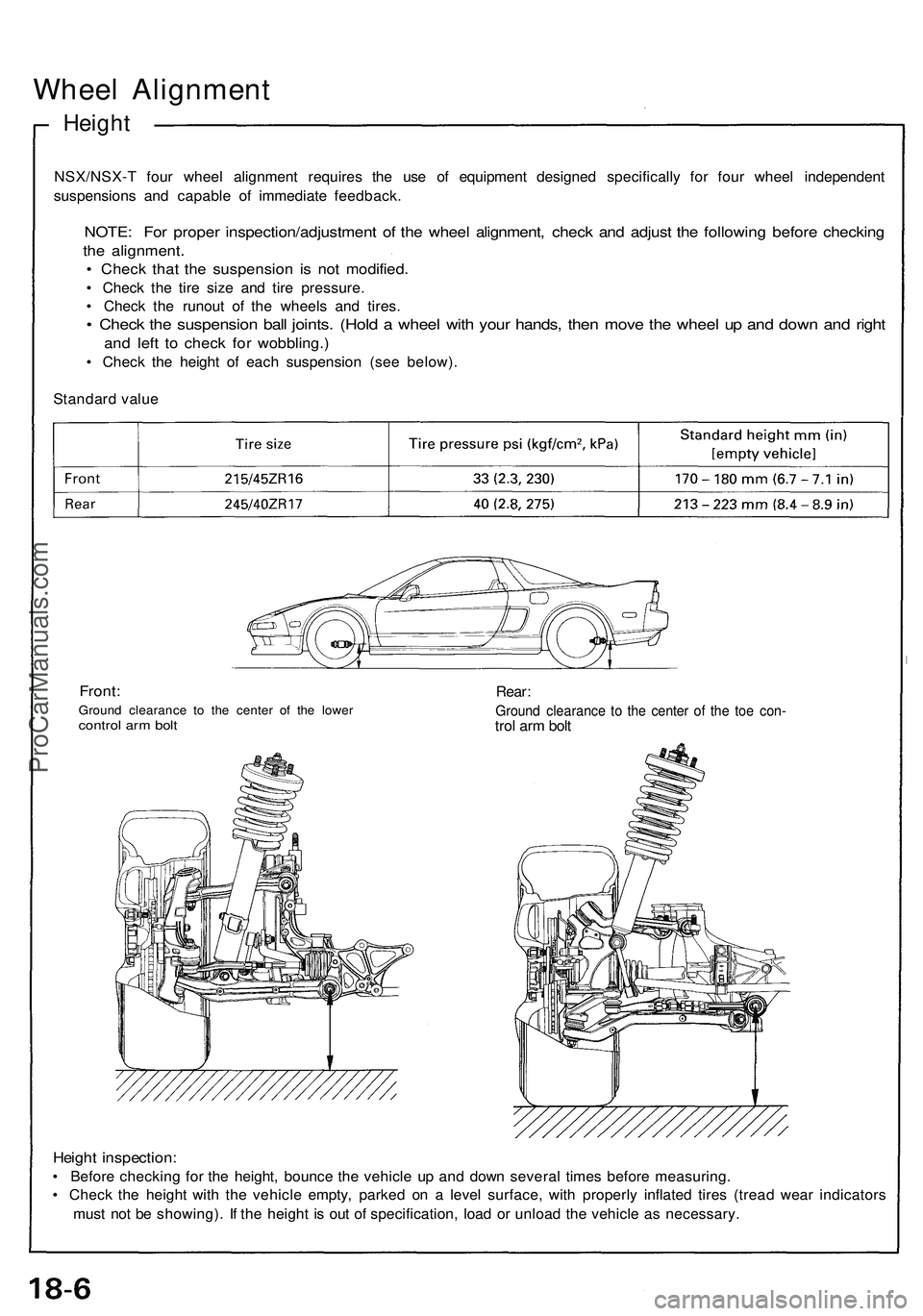
Standard value
Front:
Ground clearance to the center of the lower
control arm bolt
Rear:
Ground clearance to the center of the toe con-
trol arm bolt
Height inspection:
• Before checking for the height, bounce the vehicle up and down several times before measuring.
• Check the height with the vehicle empty, parked on a level surface, with properly inflated tires (tread wear indicators
must not be showing). If the height is out of specification, load or unload the vehicle as necessary.ProCarManuals.com
Page 940 of 1503
Front Wheel Alignment Adjusting Procedure
Adjustment
NOTE: NSX/NSX-T four wheel alignment requires the use of equipment designed specifically for four wheel independent
suspensions and capable of immediate feedback.
The NSX/NSX-T suspension can be adjusted for camber, caster (front only), and toe. However, because each of them
relates to the other, the camber changes when the toe is adjusted for example. Therefore, the total adjustment of the
front/rear wheel alignment is required whenever one of the elements (camber, caster, or toe) is adjusted.
Front wheel alignment adjusting procedure
Measure and adjust both camber and toe of the
left side.
Measure and adjust both camber and toe of the
right side.
Adjust caster on both sides.
Measure and readjust both camber and toe of
the left side.
Measure and readjust both camber and toe of
the right side.
TOP VIEW:
CASTER
TOE
CAMBER
Check tire pressure on both sides.
Check the ride height on both sides.ProCarManuals.com
Page 941 of 1503

Wheel Alignmen t
Front Whee l Alignmen t Adjustmen t Procedur e
NOTE:
• NSX/NSX- T fou r whee l alignmen t require s th e us e o f
equipmen t designe d specificall y fo r fou r whee l in -
dependen t suspension s an d capabl e of immediat e
feedback.
• Th e rid e heigh t i s ver y importan t fo r settin g th e align -
ment . Fo r ever y 1 0 m m (0. 4 in ) of chang e i n th e
fron t rid e height , th e cambe r wil l chang e approx -
imately 1 0 minutes .
• Th e fron t alignmen t setting s o n th e NS X ar e
interactive .
• A sligh t chang e i n to e wil l dramaticall y chang e th e
camber .
• Alway s inspec t an d adjus t th e fron t whee l alignmen t
wit h th e steerin g whee l i n th e straigh t ahea d
position .
1. Driv e th e vehicl e o n th e alignmen t rack .
2 . Chec k th e tir e pressur e an d rid e heigh t (se e pag e
18-6 ).
3 . Cente r th e steerin g whee l i n th e straigh t ahea d
position , an d loc k i t i n plac e wit h th e steerin g lock .
4 . Se t th e alignmen t equipmen t followin g th e
manufacturer' s instructions .
5 . Measur e an d adjus t th e cambe r an d to e o n th e lef t
side , the n measur e an d adjus t th e righ t side .
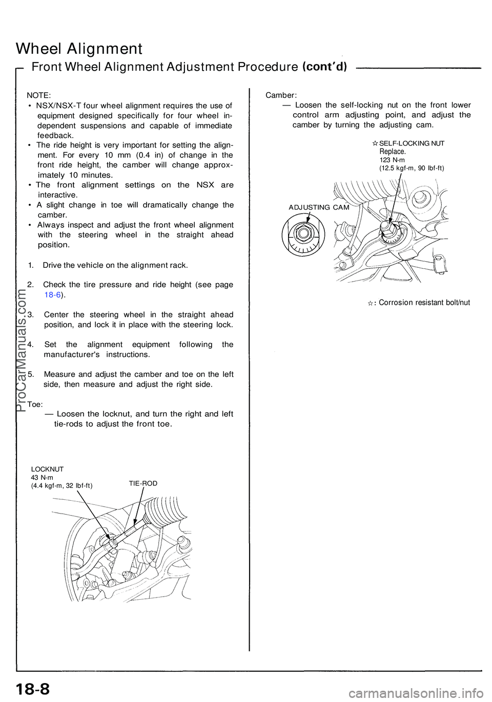
Toe:
— Loose n th e locknut , an d tur n th e righ t an d lef t
tie-rod s t o adjus t th e fron t toe .
LOCKNU T43 N- m(4.4 kgf-m , 3 2 Ibf-ft )TIE-RO D
Camber :
— Loose n th e self-lockin g nu t o n th e fron t lowe r
contro l ar m adjustin g point , an d adjus t th e
cambe r b y turnin g th e adjustin g cam .
SELF-LOCKIN G NU TReplace .123 N- m(12. 5 kgf-m , 9 0 Ibf-ft )
Corrosio n resistan t bolt/nu t
ADJUSTIN G CA M
ProCarManuals.com
Page 944 of 1503
Rear Wheel Alignment Adjusting Procedure
Rear wheel alignment adjusting procedure
Check tire pressure on both sides.
Check the ride height on both sides.
Adjust both camber and toe of the left side.
Adjust both camber and toe of the right side.
TOP VIEW:
CAMBER
TOEProCarManuals.com
Page 994 of 1503

Tests
Brake Booster
Functional Test
1. With the engine stopped, depress the brake pedal
several times to deplete the vacuum reservoir, then
depress the pedal hard and hold it for 15 seconds. If
the pedal sinks, either the master cylinder is
bypassing internally, or the brake system (master
cylinder, lines, modulator, proportioning valve, or
calipers) is leaking.
2. Start the engine with the pedal depressed. If the
pedal sinks slightly, the vacuum booster is operat-
ing normally, if the pedal height does not vary, the
booster or check valve is faulty.
3. With the engine running, depress the brake pedal
lightly. Apply just enough pressure to hold back
automatic transmission creep. If the brake pedal
sinks more than 10 mm (3/8 in.) in three minutes,
the master cylinder is faulty. A slight change in
pedal height when the A/C compressor cycles on
and off if normal. (The A/C compressor load
changes the vacuum available to the booster.)
Leak Test
1. Depress the brake pedal with the engine running,
then stop the engine. If the pedal height does not
vary while depressed for 30 seconds, the vacuum
booster is OK. If the pedal rises, the booster is
faulty.
2. With the engine stopped, depress the brake pedal
several times using normal pressure. When the
pedal is first depressed, it should be low. On con-
secutive applications, the pedal height should grad-
ually rise. If the pedal position does not vary, check
the booster check valve.
Booster Check Valve Test
1. Disconnect the brake booster vacuum hose at the
booster or at the booster side of the valve.
2. Start the engine and let it idle. There should be vac-
uum. If no vacuum is available, the check valve is
not working properly. Replace the check valve and
retest.ProCarManuals.com
Page 1119 of 1503
Hood
Replacement/Adjustment
1. Disconnect the washer hose at the Y-joint, then pull it out of the hood.
2. Remove the hood by removing the hood mounting bolts on each side.
3. To remove the hood hinges, remove the front windshield lower molding.
ALIGNMENT:
• The hood hinges can be adjusted right and left as well as fore and aft by using the elongated holes.
• The hood hinges should be shimmed to adjust the height of the hood at the rear edge.
• Adjust the hood latch to obtain the proper height at the forward edge.
4. Installation is the reverse of the removal procedure.
NOTE: Adjust the hood alignment.
SHIM
Use shims as required to make
the hood fit flush with the front
bumper at the front edge.ProCarManuals.com
Page 1297 of 1503
Sending Uni t Tes t
Do no t smok e whil e workin g o n th e fue l
system . Kee p ope n flam e awa y fro m wor k area .
1 . Remov e th e rea r bulkhea d pane l behin d th e driver' s
seat , the n remov e th e acces s panel .
2 . Wit h th e ignitio n switc h OFF , disconnec t th e 3 P con -
necto r fro m th e fue l gaug e sendin g unit .
3 . Remov e th e fiv e nuts , the n tak e th e fue l gaug e send -
in g uni t assembl y ou t o f th e fue l tank .
FUEL GAUG E SENDIN GUNIT ASSEMBL Y
4. Measur e th e resistanc e betwee n th e A an d B termi -
nal s b y movin g th e floa t t o th e height s liste d fo r E
(EMPTY) , 1/ 2 (HAL F FULL ) an d F (FULL) .
Floa t Positio n
Resistanc e
E
105-110
1/2
25.5-39. 5
F
2-5
(Botto m o f th e fue l tank )
Distanc e fro m floa t t o tan k botto m
E
1.16 in
(29. 5 mm )
1/2
5.5 5 in
(14 1 mm )
F
10.4 in
(26 3 mm )
5. I f unabl e t o obtai n th e abov e readings , replac e th e
fue l gaug e sendin g unit .
ProCarManuals.com
Page:
< prev 1-8 9-16 17-24