1997 ACURA NSX brake light
[x] Cancel search: brake lightPage 370 of 1503
3-15
T
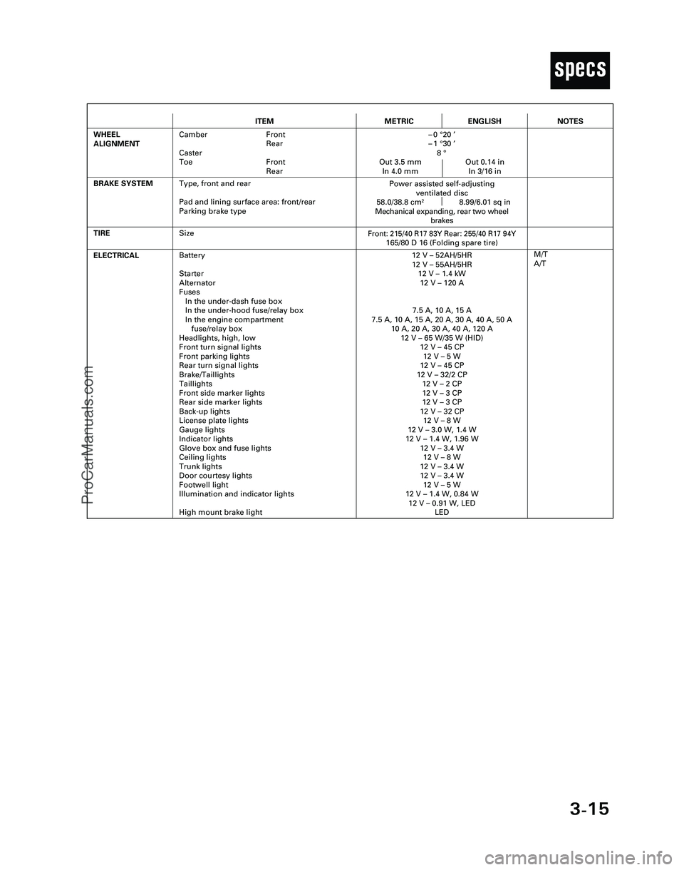
ITEMMETRICENGLISH
ELECTRICALBattery
Starter
Alternator
Fuses
In the under-dash fuse box
In the under-hood fuse/relay box
In the engine compartment
fuse/relay box
Headlights, high, low
Front turn signal lights
Front parking lights
Rear turn signal lights
Brake/Taillights
Taillights
Front side marker lights
Rear side marker lights
Back-up lights
License plate lights
Gauge lights
Indicator lights
Glove box and fuse lights
Ceiling lights
Trunk lights
Door courtesy lights
Footwell light
Illumination and indicator lights
High mount brake light12 V – 52AH/5HR
12 V – 55AH/5HR
12 V – 1.4 kW
12 V – 120 A
7.5 A, 10 A, 15 A
7.5 A, 10 A, 15 A, 20 A, 30 A, 40 A, 50 A
10 A, 20 A, 30 A, 40 A, 120 A
12 V – 65 W/35 W (HID)
12 V – 45 CP
12 V – 5 W
12 V – 45 CP
12 V – 32/2 CP
12 V – 2 CP
12 V – 3 CP
12 V – 3 CP
12 V – 32 CP
12 V – 8 W
12 V – 3.0 W, 1.4 W
12 V – 1.4 W, 1.96 W
12 V – 3.4 W
12 V – 8 W
12 V – 3.4 W
12 V – 3.4 W
12 V – 5 W
12 V – 1.4 W, 0.84 W
12 V – 0.91 W, LED
LED
TIRE
M/T
A/T
BRAKE SYSTEM
Front: 215/40 R17 83Y Rear: 255/40 R17 94Y165/80 D 16 (Folding spare tire)
Power assisted self-adjusting
ventilated disc
58.0/38.8 cm
28.99/6.01 sq in
Mechanical expanding, rear two wheel
brakes
WHEEL
ALIGNMENTCamber Front
Rear
Caster
Toe Front
Rear–0 °20 ’
–1 °30 ’
8 °
Out 3.5 mm Out 0.14 in
In 4.0 mm In 3/16 in
NOTES
Size
Type, front and rear
Pad and lining surface area: front/rear
Parking brake type
*04-NSX (61SW004)SEC03(01-16) 9/22/04 1:49 PM Page 3-15
ProCarManuals.com
Page 576 of 1503
Troubleshooting
Engine Control Module Terminal Arrangement (cont'd)
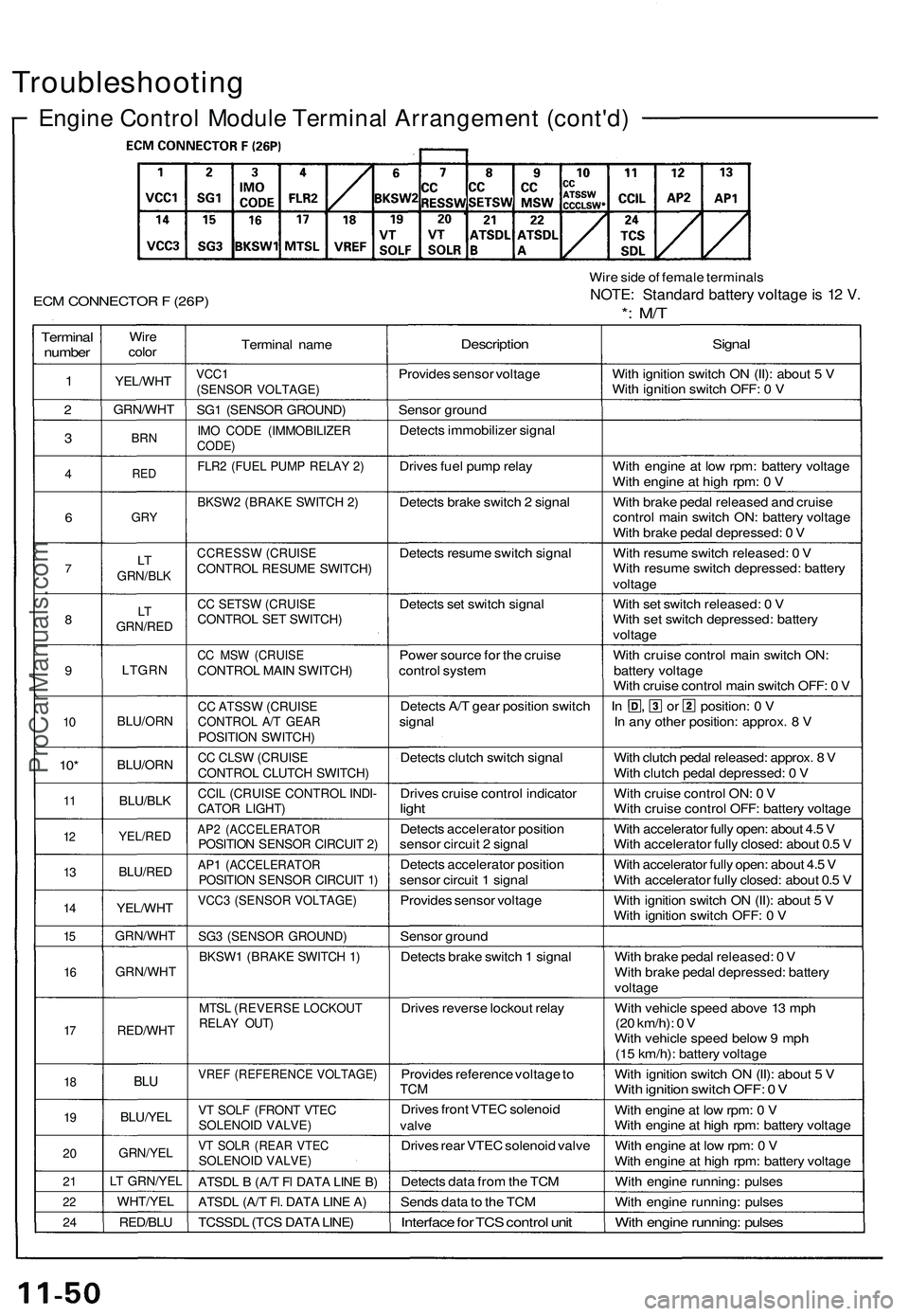
ECM CONNECTOR F (26P)
Wire side of female terminals
NOTE: Standard battery voltage is 12 V.
*: M/T
Terminal
number
1
2
3
4
6
7
8
9
10
10*
11
12
13
14
15
16
17
18
19
20
21
22
24
Wire
color
YEL/WHT
GRN/WHT
BRN
RED
GRY
LT
GRN/BLK
LT
GRN/RED
LTGRN
BLU/ORN
BLU/ORN
BLU/BLK
YEL/RED
BLU/RED
YEL/WHT
GRN/WHT
GRN/WHT
RED/WHT
BLU
BLU/YEL
GRN/YEL
LT GRN/YEL
WHT/YEL
RED/BLU
Terminal name
VCC1
(SENSOR VOLTAGE)
SG1 (SENSOR GROUND)
IMO CODE (IMMOBILIZER
CODE)
FLR2 (FUEL PUMP RELAY 2)
BKSW2 (BRAKE SWITCH 2)
CCRESSW (CRUISE
CONTROL RESUME SWITCH)
CC SETSW (CRUISE
CONTROL SET SWITCH)
CC MSW (CRUISE
CONTROL MAIN SWITCH)
CC ATSSW (CRUISE
CONTROL A/T GEAR
POSITION SWITCH)
CC CLSW (CRUISE
CONTROL CLUTCH SWITCH)
CCIL (CRUISE CONTROL INDI-
CATOR LIGHT)
AP2 (ACCELERATOR
POSITION SENSOR CIRCUIT 2)
AP1 (ACCELERATOR
POSITION SENSOR CIRCUIT 1)
VCC3 (SENSOR VOLTAGE)
SG3 (SENSOR GROUND)
BKSW1 (BRAKE SWITCH 1)
MTSL (REVERSE LOCKOUT
RELAY OUT)
VREF (REFERENCE VOLTAGE)
VT SOLF (FRONT VTEC
SOLENOID VALVE)
VT SOLR (REAR VTEC
SOLENOID VALVE)
ATSDL B (A/T Fl DATA LINE B)
ATSDL (A/T Fl. DATA LINE A)
TCSSDL (TCS DATA LINE)
Description
Provides sensor voltage
Sensor ground
Detects immobilizer signal
Drives fuel pump relay
Detects brake switch 2 signal
Detects resume switch signal
Detects set switch signal
Power source for the cruise
control system
Detects A/T gear position switch
signal
Detects clutch switch signal
Drives cruise control indicator
light
Detects accelerator position
sensor circuit 2 signal
Detects accelerator position
sensor circuit 1 signal
Provides sensor voltage
Sensor ground
Detects brake switch 1 signal
Drives reverse lockout relay
Provides reference voltage to
TCM
Drives front VTEC solenoid
valve
Drives rear VTEC solenoid valve
Detects data from the TCM
Sends data to the TCM
Interface for TCS control unit
Signal
With ignition switch ON (II): about 5 V
With ignition switch OFF: 0 V
With engine at low rpm: battery voltage
With engine at high rpm: 0 V
With brake pedal released and cruise
control main switch ON: battery voltage
With brake pedal depressed: 0 V
With resume switch released: 0 V
With resume switch depressed: battery
voltage
With set switch released: 0 V
With set switch depressed: battery
voltage
With cruise control main switch ON:
battery voltage
With cruise control main switch OFF: 0 V
In , or position: 0 V
In any other position: approx. 8 V
With clutch pedal released: approx. 8 V
With clutch pedal depressed: 0 V
With cruise control ON: 0 V
With cruise control OFF: battery voltage
With accelerator fully open: about 4.5 V
With accelerator fully closed: about 0.5 V
With accelerator fully open: about 4.5 V
With accelerator fully closed: about 0.5 V
With ignition switch ON (II): about 5 V
With ignition switch OFF: 0 V
With brake pedal released: 0 V
With brake pedal depressed: battery
voltage
With vehicle speed above 13 mph
(20 km/h): 0 V
With vehicle speed below 9 mph
(15 km/h): battery voltage
With ignition switch ON (II): about 5 V
With ignition switch OFF: 0 V
With engine at low rpm: 0 V
With engine at high rpm: battery voltage
With engine at low rpm: 0 V
With engine at high rpm: battery voltage
With engine running: pulses
With engine running: pulses
With engine running: pulsesProCarManuals.com
Page 602 of 1503
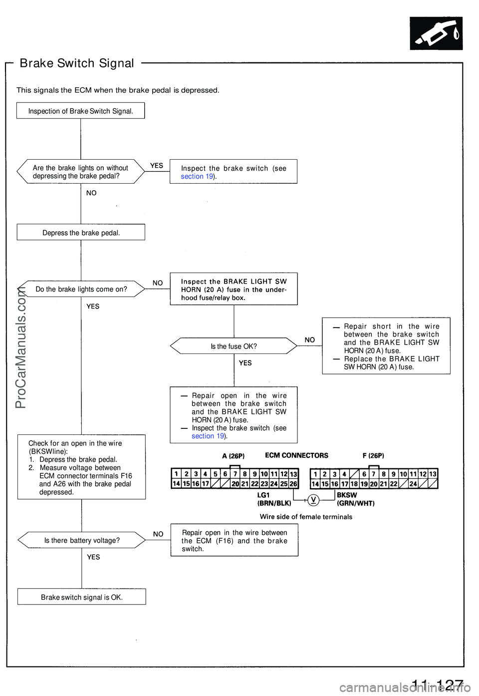
Brake Switc h Signa l
This signal s th e EC M whe n th e brak e peda l i s depressed .
Are th e brak e light s o n withou t
depressin g th e brak e pedal ? Inspec
t th e brak e switc h (se e
sectio n 19 ).
Depres s th e brak e pedal .
D o th e brak e light s com e on ?
Is th e fus e OK ?
Chec k fo r a n ope n in th e wir e
(BKS W line) :
1 . Depres s th e brak e pedal .
2 . Measur e voltag e betwee n
EC M connecto r terminal s F1 6
an d A2 6 wit h th e brak e peda l
depressed . Repai
r shor t i n th e wir e
betwee n th e brak e switc h
an d th e BRAK E LIGH T S W
HOR N (2 0 A ) fuse .
Replac e th e BRAK E LIGH T
S W HOR N (2 0 A ) fuse .
I s ther e batter y voltage ? Repai
r ope n i n th e wir e betwee n
th e EC M (F16 ) an d th e brak e
switch .
11-127
Inspectio n o f Brak e Switc h Signal .
Brak e switc h signa l i s OK . Repai
r ope n i n th e wir e
betwee n th e brak e switc h
an d th e BRAK E LIGH T S W
HOR N (2 0 A ) fuse .
Inspec t th e brak e switc h (se e
sectio n 19 ).
ProCarManuals.com
Page 836 of 1503
Installation (cont'd)
Transmission
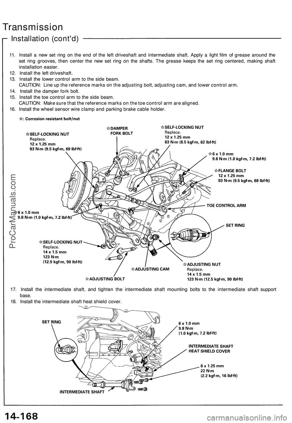
11. Install a new set ring on the end of the left driveshaft and intermediate shaft. Apply a light film of grease around the
set ring grooves, then center the new set ring on the shafts. The grease keeps the set ring centered, making shaft
installation easier.
12. Install the left driveshaft.
13. Install the lower control arm to the side beam.
CAUTION: Line up the reference marks on the adjusting bolt, adjusting cam, and lower control arm.
14. Install the damper fork bolt.
15. Install the toe control arm to the side beam.
CAUTION: Make sure that the reference marks on the toe control arm are aligned.
16. Install the wheel sensor wire clamp and parking brake cable holder.
17. Install the intermediate shaft, and tighten the intermediate shaft mounting bolts to the intermediate shaft support
base.
18. Install the intermediate shaft heat shield cover.ProCarManuals.com
Page 983 of 1503
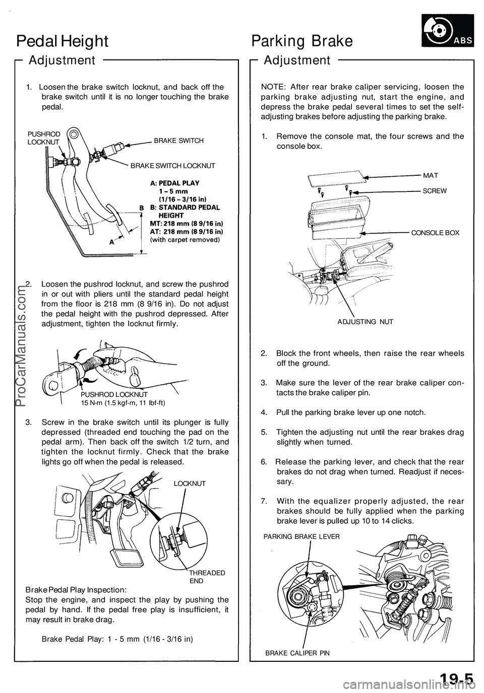
Pedal Heigh t
Adjustmen t
1. Lo osen th e brak e switc h locknut , an d bac k of f th e
brak e switc h unti l i t i s n o longe r touchin g th e brak e
pedal .
PUSHRO D
LOCKNU TBRAKE SWITC H
BRAKE SWITC H LOCKNU T
2. Loose n th e pushro d locknut , an d scre w th e pushro d
i n o r ou t wit h plier s unti l th e standar d peda l heigh t
fro m th e floo r i s 21 8 m m (8 9/1 6 in) . D o no t adjus t
th e peda l heigh t wit h th e pushro d depressed . Afte r
adjustment , tighte n th e locknu t firmly .
PUSHRO D LOCKNU T
1 5 N- m (1. 5 kgf-m , 1 1 Ibf-ft )
3. Scre w in th e brak e switc h unti l it s plunge r i s full y
depresse d (threade d en d touchin g th e pa d o n th e
peda l arm) . The n bac k of f th e switc h 1/ 2 turn , an d
tighte n th e locknu t firmly . Chec k tha t th e brak e
light s g o of f whe n th e peda l i s released .
LOCKNUT
THREADE DEND
Brak e Peda l Pla y Inspection :
Sto p th e engine , an d inspec t th e pla y b y pushin g th e
peda l b y hand . I f th e peda l fre e pla y i s insufficient , i t
ma y resul t i n brak e drag .
Brake Peda l Play : 1 - 5 m m (1/1 6 - 3/1 6 in )
Parkin g Brak e
Adjustmen t
NOTE: Afte r rea r brak e calipe r servicing , loose n th e
parkin g brak e adjustin g nut , star t th e engine , an d
depres s th e brak e peda l severa l time s t o se t th e self -
adjustin g brake s befor e adjustin g th e parkin g brake .
1 . Remov e th e consol e mat , th e fou r screw s an d th e
consol e box .
CONSOL E BO X
ADJUSTIN G NU T
2. Bloc k th e fron t wheels , the n rais e th e rea r wheel s
of f th e ground .
3 . Mak e sur e th e leve r o f th e rea r brak e calipe r con -
tact s th e brak e calipe r pin .
4 . Pul l th e parkin g brak e leve r u p on e notch .
5 . Tighte n th e adjustin g nu t unti l th e rea r brake s dra g
slightl y whe n turned .
6 . Releas e th e parkin g lever , an d chec k tha t th e rea r
brake s d o no t dra g whe n turned . Readjus t i f neces -
sary.
7. Wit h th e equalize r properl y adjusted , th e rea r
brake s shoul d b e full y applie d whe n th e parkin g
brak e leve r i s pulle d u p 1 0 to 1 4 clicks .
PARKIN G BRAK E LEVE R
BRAKE CALIPE R PI N
MA T
SCRE W
ProCarManuals.com
Page 994 of 1503
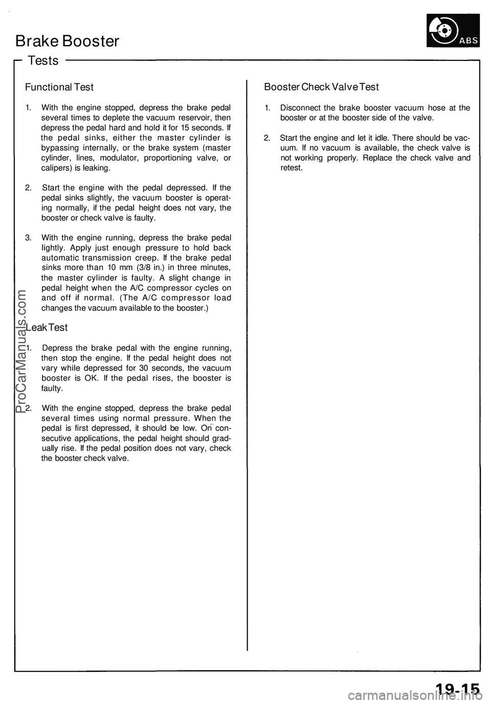
Tests
Brake Booster
Functional Test
1. With the engine stopped, depress the brake pedal
several times to deplete the vacuum reservoir, then
depress the pedal hard and hold it for 15 seconds. If
the pedal sinks, either the master cylinder is
bypassing internally, or the brake system (master
cylinder, lines, modulator, proportioning valve, or
calipers) is leaking.
2. Start the engine with the pedal depressed. If the
pedal sinks slightly, the vacuum booster is operat-
ing normally, if the pedal height does not vary, the
booster or check valve is faulty.
3. With the engine running, depress the brake pedal
lightly. Apply just enough pressure to hold back
automatic transmission creep. If the brake pedal
sinks more than 10 mm (3/8 in.) in three minutes,
the master cylinder is faulty. A slight change in
pedal height when the A/C compressor cycles on
and off if normal. (The A/C compressor load
changes the vacuum available to the booster.)
Leak Test
1. Depress the brake pedal with the engine running,
then stop the engine. If the pedal height does not
vary while depressed for 30 seconds, the vacuum
booster is OK. If the pedal rises, the booster is
faulty.
2. With the engine stopped, depress the brake pedal
several times using normal pressure. When the
pedal is first depressed, it should be low. On con-
secutive applications, the pedal height should grad-
ually rise. If the pedal position does not vary, check
the booster check valve.
Booster Check Valve Test
1. Disconnect the brake booster vacuum hose at the
booster or at the booster side of the valve.
2. Start the engine and let it idle. There should be vac-
uum. If no vacuum is available, the check valve is
not working properly. Replace the check valve and
retest.ProCarManuals.com
Page 1010 of 1503
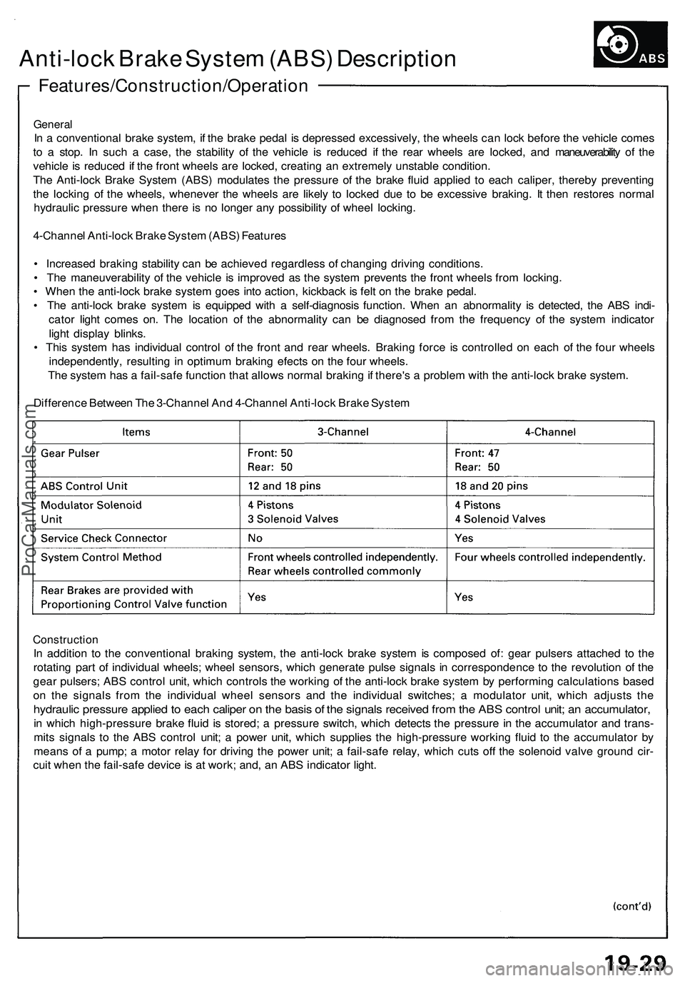
Features/Construction/Operation
Anti-lock Brake System (ABS) Description
General
In a conventional brake system, if the brake pedal is depressed excessively, the wheels can lock before the vehicle comes
to a stop. In such a case, the stability of the vehicle is reduced if the rear wheels are locked, and maneuverability of the
vehicle is reduced if the front wheels are locked, creating an extremely unstable condition.
The Anti-lock Brake System (ABS) modulates the pressure of the brake fluid applied to each caliper, thereby preventing
the locking of the wheels, whenever the wheels are likely to locked due to be excessive braking. It then restores normal
hydraulic pressure when there is no longer any possibility of wheel locking.
4-Channel Anti-lock Brake System (ABS) Features
• Increased braking stability can be achieved regardless of changing driving conditions.
• The maneuverability of the vehicle is improved as the system prevents the front wheels from locking.
• When the anti-lock brake system goes into action, kickback is felt on the brake pedal.
• The anti-lock brake system is equipped with a self-diagnosis function. When an abnormality is detected, the ABS indi-
cator light comes on. The location of the abnormality can be diagnosed from the frequency of the system indicator
light display blinks.
• This system has individual control of the front and rear wheels. Braking force is controlled on each of the four wheels
independently, resulting in optimum braking efects on the four wheels.
The system has a fail-safe function that allows normal braking if there's a problem with the anti-lock brake system.
Difference Between The 3-Channel And 4-Channel Anti-lock Brake System
Construction
In addition to the conventional braking system, the anti-lock brake system is composed of: gear pulsers attached to the
rotating part of individual wheels; wheel sensors, which generate pulse signals in correspondence to the revolution of the
gear pulsers; ABS control unit, which controls the working of the anti-lock brake system by performing calculations based
on the signals from the individual wheel sensors and the individual switches; a modulator unit, which adjusts the
hydraulic pressure applied to each caliper on the basis of the signals received from the ABS control unit; an accumulator,
in which high-pressure brake fluid is stored; a pressure switch, which detects the pressure in the accumulator and trans-
mits signals to the ABS control unit; a power unit, which supplies the high-pressure working fluid to the accumulator by
means of a pump; a motor relay for driving the power unit; a fail-safe relay, which cuts off the solenoid valve ground cir-
cuit when the fail-safe device is at work; and, an ABS indicator light.ProCarManuals.com
Page 1014 of 1503
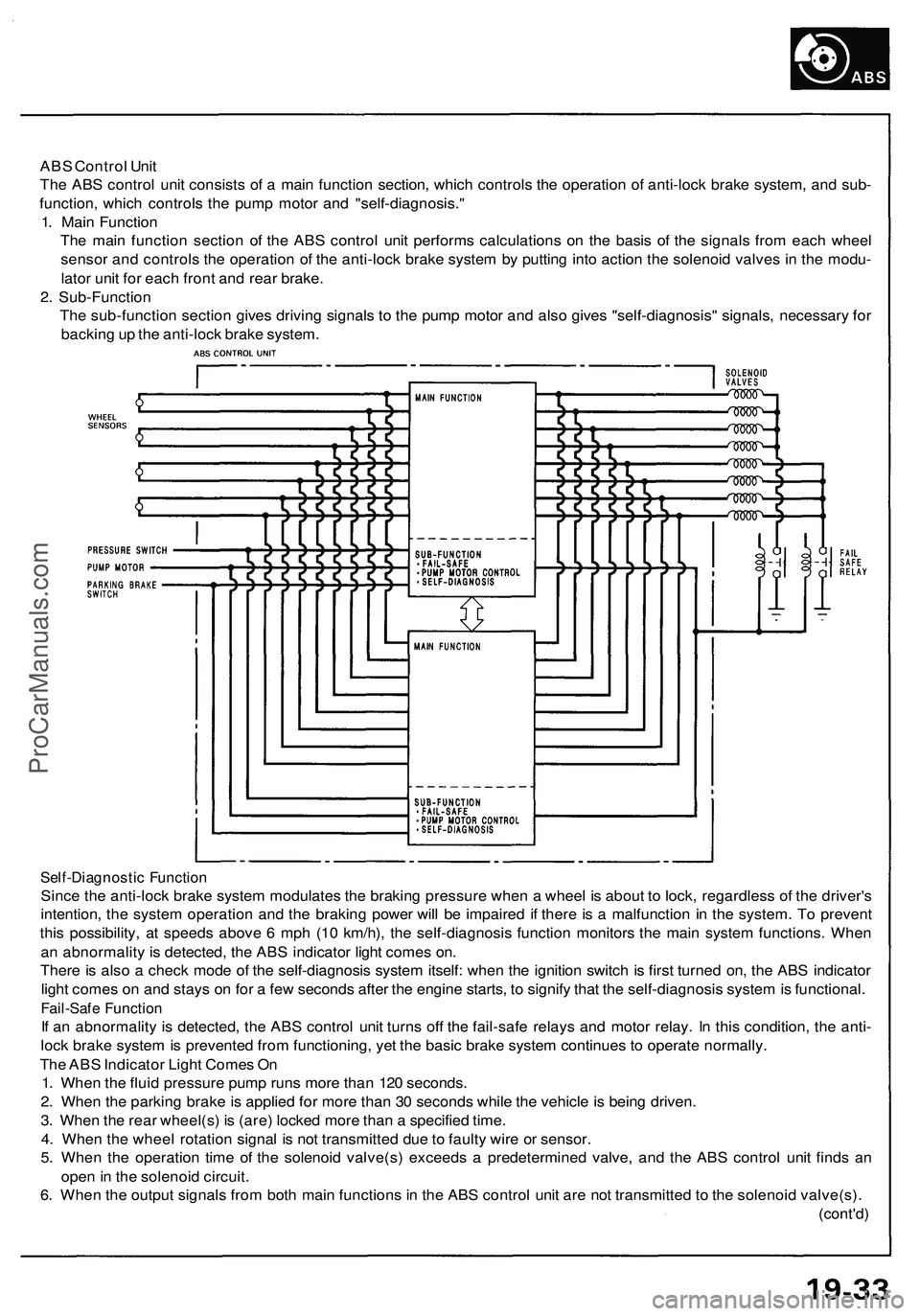
ABS Control Unit
The ABS control unit consists of a main function section, which controls the operation of anti-lock brake system, and sub-
function, which controls the pump motor and "self-diagnosis."
1. Main Function
The main function section of the ABS control unit performs calculations on the basis of the signals from each wheel
sensor and controls the operation of the anti-lock brake system by putting into action the solenoid valves in the modu-
lator unit for each front and rear brake.
2. Sub-Function
The sub-function section gives driving signals to the pump motor and also gives "self-diagnosis" signals, necessary for
backing up the anti-lock brake system.
Self-Diagnostic Function
Since the anti-lock brake system modulates the braking pressure when a wheel is about to lock, regardless of the driver's
intention, the system operation and the braking power will be impaired if there is a malfunction in the system. To prevent
this possibility, at speeds above 6 mph (10 km/h), the self-diagnosis function monitors the main system functions. When
an abnormality is detected, the ABS indicator light comes on.
There is also a check mode of the self-diagnosis system itself: when the ignition switch is first turned on, the ABS indicator
light comes on and stays on for a few seconds after the engine starts, to signify that the self-diagnosis system is functional.
Fail-Safe Function
If an abnormality is detected, the ABS control unit turns off the fail-safe relays and motor relay. In this condition, the anti-
lock brake system is prevented from functioning, yet the basic brake system continues to operate normally.
The ABS Indicator Light Comes On
1. When the fluid pressure pump runs more than 120 seconds.
2. When the parking brake is applied for more than 30 seconds while the vehicle is being driven.
3. When the rear wheel(s) is (are) locked more than a specified time.
4. When the wheel rotation signal is not transmitted due to faulty wire or sensor.
5. When the operation time of the solenoid valve(s) exceeds a predetermined valve, and the ABS control unit finds an
open in the solenoid circuit.
6. When the output signals from both main functions in the ABS control unit are not transmitted to the solenoid valve(s).
(cont'd)ProCarManuals.com