Page 271 of 1503
Lighting System
HID Lamp System Troubleshooting
1. Check the No. 49 (20 A) or No. 52 (20 A) fuse in the
main under-hood fuse/relay box.
Are the fuses OK?
YES — Go to step 2.
NO — Replace the fuse (s), and recheck.
2. Substitute a known-good HID bulb and recheck.
Does the headlight low beam come on?
YES — Replace the HID bulb.
NO — Go to step 3.
3. Disconnect the 2P connector from the inverter unit.
4. Turn the combination light switch ON.
5. Measure the voltage between the No. 2 terminal of
the inverter unit 2P connector and body ground.
7. Check for continuity between the No. 1 terminal of
the inverter unit 2P connector and body ground.
Is there continuity?
YES — Substitute a known-good inverter, and
recheck. If the symptom/indication goes away,
replace the original inverter unit.
NO — Repair open in the wire between the inverter
unit and body ground. If the wire is OK, check for
poor ground at G202 or G302.ProCarManuals.com
Page 276 of 1503
Front Turn Signal Light:
1. Open the hood.
2. Turn the bulb socket 45° counterclockwise, remove
it from the headlight assembly, then replace the
bulb.
Front Parking Light:
1. Open the hood.
2. Turn the bulb socket 45° counterclockwise, remove
it from the headlight assembly, then replace the
bulb.ProCarManuals.com
Page 1333 of 1503

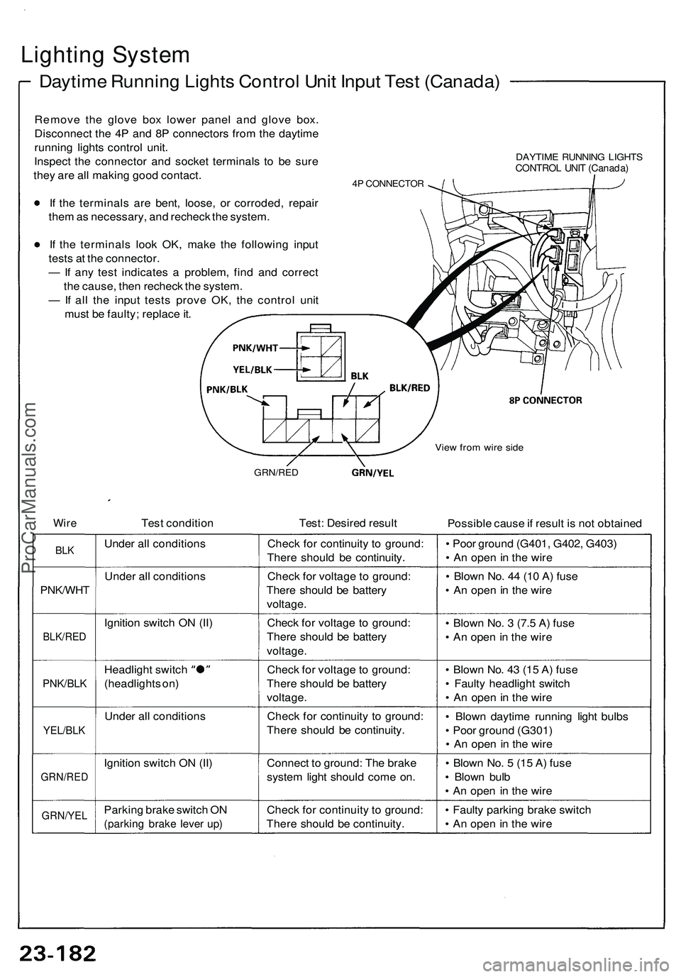
Lighting Syste m
Daytim e Runnin g Light s Contro l Uni t Inpu t Tes t (Canada )
Remove th e glov e bo x lowe r pane l an d glov e box .
Disconnec t th e 4 P an d 8 P connector s fro m th e daytim e
runnin g light s contro l unit .
Inspec t th e connecto r an d socke t terminal s t o b e sur e
the y ar e al l makin g goo d contact .
I f th e terminal s ar e bent , loose, or corroded , repai r
the m as necessary , an d rechec k th e system .
I f th e terminal s loo k OK , mak e th e followin g inpu t
test s a t th e connector .
— If an y tes t indicate s a problem , fin d an d correc t
th e cause , the n rechec k th e system .
— If al l th e inpu t test s prov e OK , th e contro l uni t
mus t b e faulty ; replac e it .
DAYTIM E RUNNIN G LIGHT SCONTRO L UNI T (Canada )
4P CONNECTO R
View fro m wir e sid e
GRN/RED
Wir eTes t conditio n Test: Desire d resul t
Possible caus e if resul t i s no t obtaine d
BLK
PNK/WH T
BLK/RED
PNK/BL K
YEL/BLK
GRN/RE D
GRN/YEL
Under al l condition s
Unde r al l condition s
Ignitio n switc h O N (II )
Headligh t switc h
(headlight s on )
Unde r al l condition s
Ignitio n switc h O N (II )
Parkin g brak e switc h O N
(parkin g brak e leve r up )
Chec k fo r continuit y t o ground :
Ther e shoul d b e continuity .
Chec k fo r voltag e t o ground :
Ther e shoul d b e batter y
voltage .
Chec k fo r voltag e t o ground :
Ther e shoul d b e batter y
voltage .
Check fo r voltag e to ground :
Ther e shoul d b e batter y
voltage .
Check fo r continuit y t o ground :
Ther e shoul d b e continuity .
Connec t t o ground : Th e brak e
syste m ligh t shoul d com e on .
Chec k fo r continuit y t o ground :
Ther e shoul d b e continuity .•
Poo r groun d (G401 , G402 , G403 )
• A n ope n in th e wir e
• Blow n No . 4 4 (1 0 A ) fus e
• A n ope n in th e wir e
• Blow n No . 3 (7. 5 A ) fus e
• A n ope n in th e wir e
• Blow n No . 4 3 (1 5 A ) fus e
• Fault y headligh t switc h
• A n ope n in th e wir e
• Blow n daytim e runnin g ligh t bulb s
• Poo r groun d (G301 )
• A n ope n in th e wir e
• Blow n No . 5 (1 5 A ) fus e
• Blow n bul b
• A n ope n i n th e wir e
• Fault y parkin g brak e switc h
• A n ope n in th e wir e
ProCarManuals.com
Page 1336 of 1503
5. Disconnect the 18P and 10P connectors.
CAUTION: Be careful not to damage the SRS wire
harness.
6. Remove the six screws, then remove the headlight-
turn signal switch assembly.
HEADLIGHT SWITCH
10P CONNECTOR
18PXJONNECTOR
TURN SIGNAL SWITCH
7. If necessary, remove the turn signal cancel unit and
cancel switch.
TURN SIGNAL
CANCEL UNIT
TURN SIGNAL
CANCEL SWITCH
8. If necessary, remove the headlight switch bulb.
HEADLIGHT SWITCH
BULB (0.91 W)ProCarManuals.com
Page 1346 of 1503
Headlights
Description
The light first forms basic pattern A after being inter-
rupted by the interrupter plate and passing through the
convex lens. The interrupter plate determines the form.
The outer lens distributes the light into pattern B.
CONVEX LENS
INTERRUPTER PLATE
BULB
REFLECTOR
OUTER LENSProCarManuals.com
Page 1349 of 1503
Headlights
Bulb Replacement
CAUTION:
Halogen headlights can become very hot in use; do
not touch them or the attaching hardware immediately
after they have been turned off.
Do not try to replace or clean the headlights with the
lights on.
1. Remove the bulb cap.
BULB
(HI:
65
W/LO:
55 W)
BULB CAP
2P CONNECTOR
2. Disconnect the 2P connector, then remove the
retaining spring and bulb.
Daytime Running Lights
(Canada)
Replacement
1. Remove the bolt, and pull out the daytime running
light, then disconnect the 2P connector.
2P
CONNECTOR
DAYTIME RUNNING LIGHT
BOLT
2. If necessary, replace the bulb.
DAYTIME RUNNING
LIGHT
BULB (32CP)
SOCKETProCarManuals.com
Page 1369 of 1503

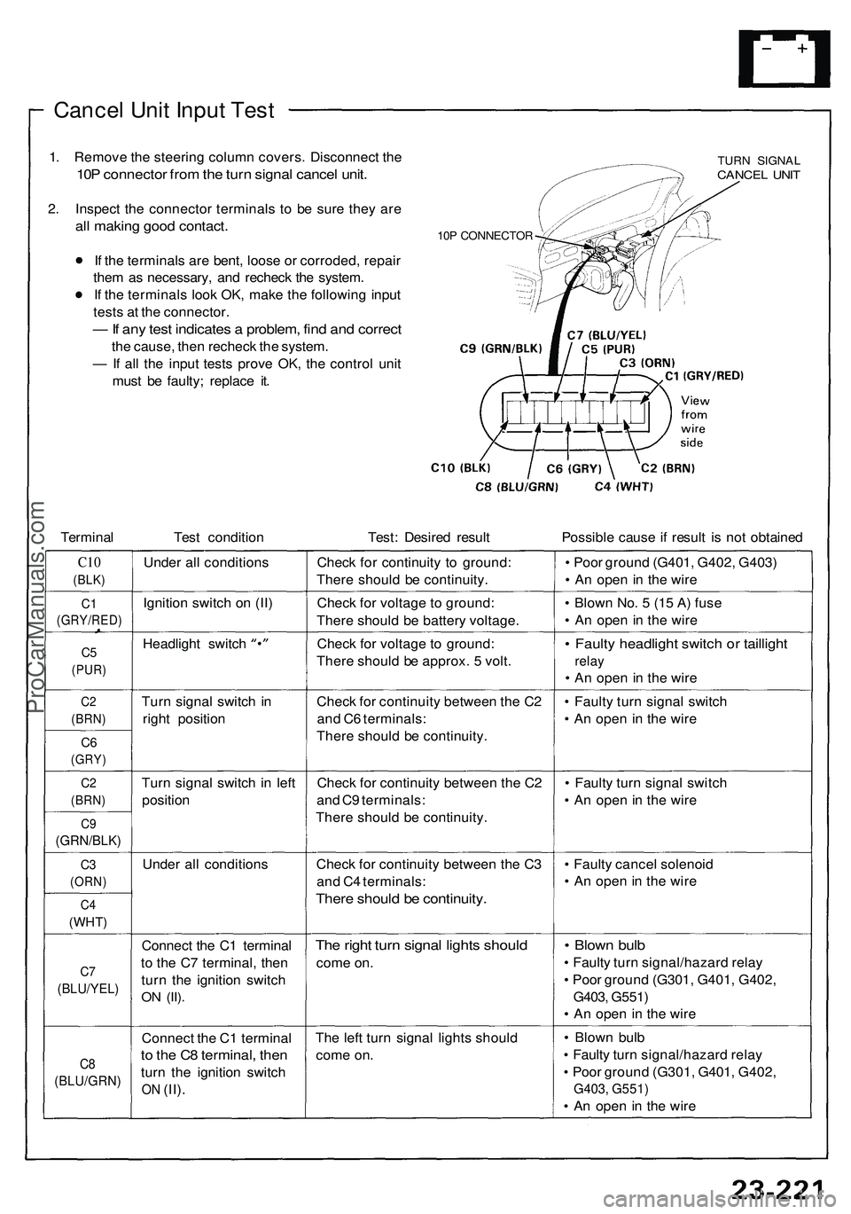
Cancel Unit Input Test
1. Remove the steering column covers. Disconnect the
10P connector from the turn signal cancel unit.
2. Inspect the connector terminals to be sure they are
all making good contact.
If the terminals are bent, loose or corroded, repair
them as necessary, and recheck the system.
If the terminals look OK, make the following input
tests at the connector.
— If any test indicates a problem, find and correct
the cause, then recheck the system.
— If all the input tests prove OK, the control unit
must be faulty; replace it.
10P CONNECTOR
TURN SIGNAL
CANCEL UNIT
Terminal
Test condition
Test: Desired result
Possible cause if result is not obtained
C10
(BLK)
Under all conditions
Check for continuity to ground:
There should be continuity.
• Poor ground (G401, G402, G403)
• An open in the wire
C1
(GRY/RED)
Ignition switch on (II)
Check for voltage to ground:
There should be battery voltage.
• Blown No. 5 (15 A) fuse
• An open in the wire
C5
(PUR)
Headlight switch
Check for voltage to ground:
There should be approx. 5 volt.
• Faulty headlight switch or taillight
relay
• An open in the wire
C2
(BRN)
Turn signal switch in
right position
C6
(GRY)
Check for continuity between the C2
and C6 terminals:
There should be continuity.
• Faulty turn signal switch
• An open in the wire
C2
(BRN)
Turn signal switch in left
position
C9
(GRN/BLK)
Check for continuity between the C2
and C9 terminals:
There should be continuity.
• Faulty turn signal switch
• An open in the wire
C3
(ORN)
Under all conditions
C4
(WHT)
Check for continuity between the C3
and C4 terminals:
There should be continuity.
• Faulty cancel solenoid
• An open in the wire
C7
(BLU/YEL)
Connect the C1 terminal
to the C7 terminal, then
turn the ignition switch
ON
(II).
The right turn signal lights should
come on.
• Blown bulb
• Faulty turn signal/hazard relay
• Poor ground (G301, G401, G402,
G403, G551)
• An open in the wire
C8
(BLU/GRN)
Connect the C1 terminal
to the C8 terminal, then
turn the ignition switch
ON
(II).
The left turn signal lights should
come on.
• Blown bulb
• Faulty turn signal/hazard relay
• Poor ground (G301, G401, G402,
G403, G551)
• An open in the wireProCarManuals.com
Page 1376 of 1503
1. Remove the dash lights brightness controller from
the instrument panel trim (see previous page).
2. Measure resistance between A and B terminals
while rotating the adjusting dial. Resistance should
vary from 0 to 20,000 ohms as the dial is rotated.
NOTE: Resistance will vary slightly with temperature.
HEADLIGHT
RETRACTOR SWITCH
ADJUSTING
DIAL
DASH LIGHTS
BRIGHTNESS
CONTROLLER
Controller Light Bulb Replacement
1. Remove the dash lights brightness controller.
2. Turn the socket 45° counterclockwise to remove it.
BULB (0.84 W)
Dash Lights Brightness Control
Controller TestProCarManuals.com