Page 453 of 1503
Camshafts
Inspection (cont'd)
9. Remove the camshaft holders and measure widest
portion of plastigage on each journal.
Camshaft-to-Holder Oil Clearance:
Standard (New): 0.050 - 0.089 mm
(0.002 - 0.004 in)
Service Limit: 0.15 mm (0.006 in)
PLASTIGAGE STRIP
10. If camshaft-to-holder oil clearance is out of toler-
ance:
— And camshaft has already been replaced, you
must replace the cylinder head.
— If camshaft has not been replaced, first check
total runout with the camshaft supported on V-
blocks.
Camshaft Total Runout:
Standard (New): 0.03 mm (0.0012 in) max.
Service Limit: 0.04 mm (0.0016 in)
Rotate camshaft
while measuring
— If the total runout of the camshaft is within toler-
ance, replace the cylinder head.
— If the total runout is out of tolerance, replace the
camshaft and recheck. If the oil clearance is still
out of tolerance, replace the cylinder head.
11. Check cam lobe height wear.
Cam Lobe Height Standard (New):
M/T
Check this area for wear.ProCarManuals.com
Page 458 of 1503
Cylinder Head s
Warpag e
NOTE: I f camshaft-to-holde r oi l clearance s (se e page s
6-35 , 6-36 ) ar e no t withi n specification , th e cylinde r hea d
canno t b e resurfaced .
I f camshaft-to-holde r oi l clearance s ar e withi n specifica -
tions , chec k th e cylinde r hea d fo r warpage .
• I f warpag e i s les s tha n 0.0 5 m m (0.00 2 in ) cylinde r
head resurfacin g i s no t required .
• I f warpag e i s betwee n 0.0 5 m m (0.00 2 in ) an d 0. 2
mm (0.00 8 in) , resurfac e cylinde r head .
• Maximu m resurfac e limi t i s 0. 2 m m (0.00 8 in ) base d
on a heigh t o f 1 51 m m (5.94 5 in) .
PRECISIO N STRAIGH T EDG E
Measur e alon g edges , an d thre e way s acros s center .
Cylinde r Hea d Height :
Standar d (New) : 150.9 5 - 151.0 5 m m
(5.94 3 - 5.94 7 in )
ProCarManuals.com
Page 459 of 1503

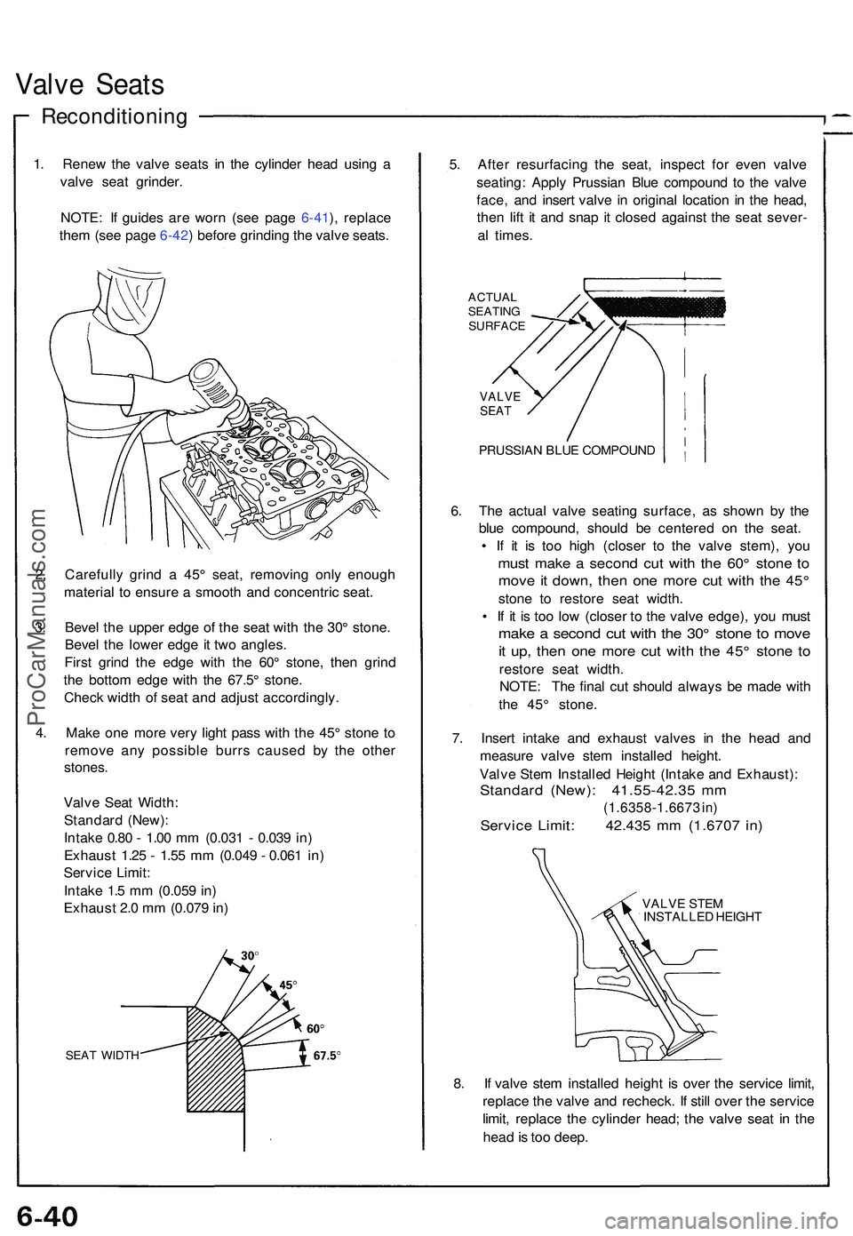
Valve Seat s
Reconditionin g
1. Rene w th e valv e seat s i n th e cylinde r hea d usin g a
valv e sea t grinder .
NOTE : I f guide s ar e wor n (se e pag e 6-41 ), replac e
the m (se e pag e 6-42 ) befor e grindin g th e valv e seats .
2 . Carefull y grin d a 45 ° seat , removin g onl y enoug h
materia l t o ensur e a smoot h an d concentri c seat .
3 . Beve l th e uppe r edg e o f th e sea t wit h th e 30 ° stone .
Beve l th e lowe r edg e i t tw o angles .
Firs t grin d th e edg e wit h th e 60 ° stone , the n grin d
th e botto m edg e wit h th e 67.5 ° stone .
Chec k widt h o f sea t an d adjus t accordingly .
4 . Mak e on e mor e ver y ligh t pas s wit h th e 45 ° ston e t o
remov e an y possibl e burr s cause d b y th e othe r
stones .
Valv e Sea t Width :
Standar d (New) :
Intak e 0.8 0 - 1.0 0 m m (0.03 1 - 0.03 9 in )
Exhaus t 1.2 5 - 1.5 5 m m (0.04 9 - 0.06 1 in )
Servic e Limit :
Intak e 1. 5 m m (0.05 9 in )
Exhaus t 2. 0 m m (0.07 9 in )
SEA T WIDT H
5. Afte r resurfacin g th e seat , inspec t fo r eve n valv e
seating : Appl y Prussia n Blu e compoun d t o th e valv e
face , an d inser t valv e i n origina l locatio n i n th e head ,
the n lif t i t an d sna p i t close d agains t th e sea t sever -
a l times .
ACTUA L
SEATIN G
SURFAC E
VALVESEAT
PRUSSIA N BLU E COMPOUN D
6. Th e actua l valv e seatin g surface , a s show n b y th e
blu e compound , shoul d b e centere d o n th e seat .
• I f i t i s to o hig h (close r t o th e valv e stem) , yo u
mus t mak e a secon d cu t wit h th e 60 ° ston e t o
mov e it down , the n on e mor e cu t wit h th e 45 °
ston e t o restor e sea t width .
• I f i t i s to o lo w (close r t o th e valv e edge) , yo u mus t
make a secon d cu t wit h th e 30 ° ston e t o mov e
it up , the n on e mor e cu t wit h th e 45 ° ston e t o
restor e sea t width .
NOTE : Th e fina l cu t shoul d alway s b e mad e wit h
th e 45 ° stone .
7 . Inser t intak e an d exhaus t valve s i n th e hea d an d
measur e valv e ste m installe d height .
Valv e Ste m Installe d Heigh t (Intak e an d Exhaust) :
Standard (New) : 41.55-42.3 5 m m
(1.6358-1.667 3 in )
Servic e Limit : 42.43 5 m m (1.670 7 in )
VALV E STE M
INSTALLE D HEIGH T
8. I f valv e ste m installe d heigh t i s ove r th e servic e limit ,
replac e th e valv e an d recheck . I f stil l ove r th e servic e
limit , replac e th e cylinde r head ; th e valv e sea t i n th e
hea d is to o deep .
ProCarManuals.com
Page 462 of 1503
7. Appl y a thi n coa t o f clea n engin e oi l t o th e outsid e o f
th e ne w valv e guide . Instal l th e guid e fro m th e
camshaf t sid e o f th e head ; us e th e specia l too l t o
driv e th e guid e i n t o th e specifie d installe d height . I f
yo u hav e al l 1 2 guide s t o do , yo u ma y hav e t o rehea t
th e head .
VALV E GUID EDRIVER , 5. 5 m m07742-001010 0
Valve Guid e Installe d Height :
Intake: 13.75-14.2 5 m m (0.541-0.56 1 in )
Exhaust : 13.75-14.2 5 m m (0.541-0.56 1 in )
ProCarManuals.com
Page 525 of 1503

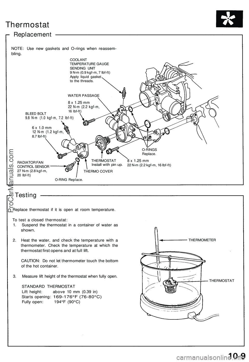
Thermostat
Replacemen t
NOTE: Us e ne w gasket s an d O-ring s whe n reassem -
bling.
COOLAN TTEMPERATUR E GAUG ESENDIN G UNI T
9 N- m (0. 9 kgf-m , 7 Ibf-ft )
Appl y liqui d gaske t
t o th e threads .
WATE R PASSAG E
BLEED BOL T9.8 N- m (1. 0 kgf-m , 7. 2 Ibf-ft )
8 x 1.2 5 mm22 N- m (2. 2 kgf-m ,16 Ibf-ft )
RADIATO R FA N
CONTRO L SENSO R
2 7 N- m (2. 8 kgf-m ,
20 Ibf-ft )
6 x 1. 0 m m12 N- m (1. 2 kgf-m ,8.7 Ibf-ft )
THERMOSTAT
Install wit h pi n up .
THERM O COVE R
8 x 1.2 5 mm22 N- m (2. 2 kgf-m , 1 6 Ibf-ft )
O-RIN G Replace .
Testing
Replac e thermosta t i f i t i s ope n a t roo m temperature .
T o tes t a close d thermostat :
1 . Suspen d th e thermosta t i n a containe r o f wate r a s
shown .
2. Hea t th e water , an d chec k th e temperatur e wit h a
thermometer . Chec k th e temperatur e a t whic h th e
thermosta t firs t open s an d a t ful l lift .
CAUTION : D o no t le t thermomete r touc h th e botto m
o f th e ho t container .
3 . Measur e lif t heigh t o f th e thermosta t whe n full y open .
STANDAR D THERMOSTA T
Lif t height : abov e 1 0 m m (0.3 9 in )
Start s opening :
169-176° F (76-80°C)
Fully open : 194° F (90°C )
THERMOMETE R
THERMOSTA T
O-RINGSReplace .
ProCarManuals.com
Page 884 of 1503

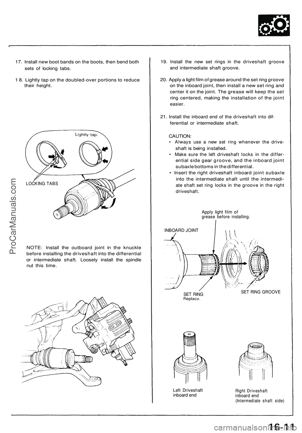
17. Install new boot bands on the boots, then bend both
sets of locking tabs.
1 8. Lightly tap on the doubled-over portions to reduce
their height.
NOTE: Install the outboard joint in the knuckle
before installing the driveshaft into the differential
or intermediate shaft. Loosely install the spindle
nut this time.
19. Install the new set rings in the driveshaft groove
and intermediate shaft groove.
20. Apply a light film of grease around the set ring groove
on the inboard joint, then install a new set ring and
center it on the joint. The grease will keep the set
ring centered, making the installation of the joint
easier.
21. Install the inboard end of the driveshaft into dif-
ferential or intermediate shaft.
CAUTION:
• Always use a new set ring whenever the drive-
shaft is being installed.
• Make sure the left driveshaft locks in the differ-
ential side gear groove, and the inboard joint
subaxle bottoms in the differential.
• Insert the right driveshaft inboard joint subaxle
into the intermediate shaft until the intermedi-
ate shaft set ring locks in the groove in the right
driveshaft.
Apply light film of
grease before installing.
INBOARD JOINT
SET RING
SET RING GROOVE
Left Driveshaft
inboard end
Right Driveshaft
inboard end
(Intermediate shaft side)
LOCKING TABSProCarManuals.com
Page 893 of 1503
System Description
Steering Column
The NSX/NSX-T has a tilt/telescopic steering column. The tilt/telescopic mechanism makes it possible to adjust the steer-
ing wheel in fore and aft, and up and down directions.
Tilt Mechanism
In the upper portion of the steering column is a joint on the steering shaft. This joint allows the steering wheel to be
adjusted
up or
down. When
the
tilt
lever
is
operated,
the
lock gears
are
detached
from
the
column
gear
to
release
the
lock.
The column moves upward or downward on two pivot bolts. When the tilt lever is returned to a fixed position after select-
ing the steering wheel height, the lock gear is engaged with the column gear to secure the column.ProCarManuals.com
Page 932 of 1503

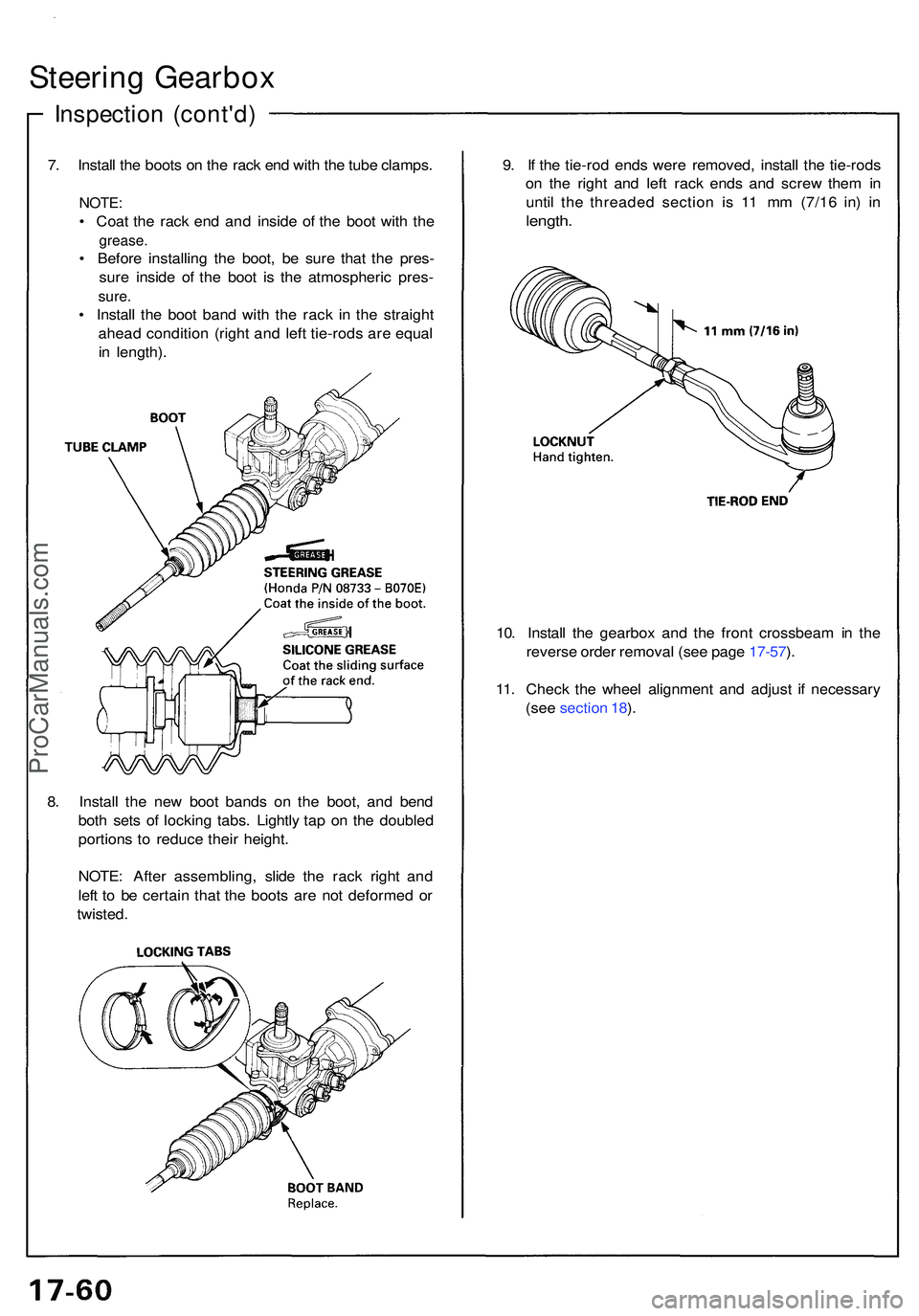
Steering Gearbo x
Inspectio n (cont'd )
7. Instal l th e boot s o n th e rac k en d wit h th e tub e clamps .
NOTE:
• Coa t th e rac k en d an d insid e o f th e boo t wit h th e
grease .
• Befor e installin g th e boot , b e sur e tha t th e pres -
sur e insid e of the boo t i s th e atmospheri c pres -
sure.
• Instal l th e boo t ban d wit h th e rac k i n th e straigh t
ahea d conditio n (righ t an d lef t tie-rod s ar e equa l
i n length) . 9
. I f th e tie-ro d end s wer e removed , instal l th e tie-rod s
o n th e righ t an d lef t rac k end s an d scre w the m in
until the threade d sectio n i s 1 1 m m (7/1 6 in ) i n
length .
10. Instal l th e gearbo x an d th e fron t crossbea m in th e
revers e orde r remova l (se e pag e 17-57 ).
11 . Chec k th e whee l alignmen t an d adjus t i f necessar y
(se e sectio n 18 ).
8 . Instal l th e ne w boo t band s o n th e boot , an d ben d
bot h set s o f lockin g tabs . Lightl y ta p o n th e double d
portion s t o reduc e thei r height .
NOTE : Afte r assembling , slid e th e rac k righ t an d
lef t t o b e certai n tha t th e boot s ar e no t deforme d o r
twisted .
ProCarManuals.com