1997 ACURA NSX service indicator
[x] Cancel search: service indicatorPage 452 of 1503
Camshafts
Inspection
NOTE:
• Do not rotate the camshaft during inspection.
• Remove the rocker arms and rocker shafts.
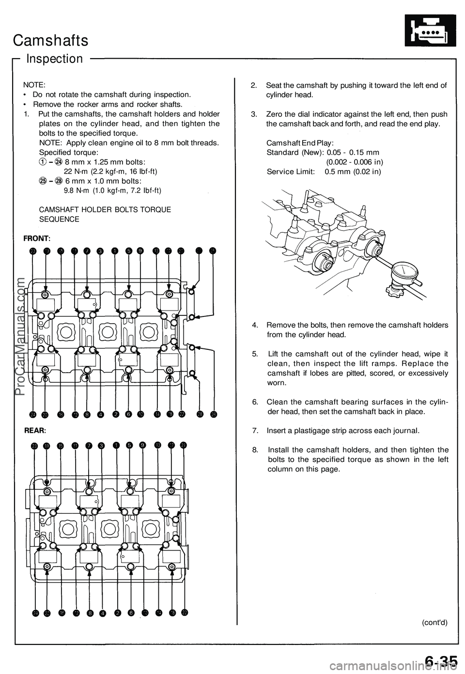
1. Put the camshafts, the camshaft holders and holder
plates on the cylinder head, and then tighten the
bolts to the specified torque.
NOTE: Apply clean engine oil to 8 mm bolt threads.
Specified torque:
8 mm x 1.25 mm bolts:
22 N-m (2.2 kgf-m, 16 Ibf-ft)
6 mm x 1.0 mm bolts:
9.8 N-m (1.0 kgf-m, 7.2 Ibf-ft)
CAMSHAFT HOLDER BOLTS TORQUE
SEQUENCE
2. Seat the camshaft by pushing it toward the left end of
cylinder head.
3. Zero the dial indicator against the left end, then push
the camshaft back and forth, and read the end play.
Camshaft End Play:
Standard (New): 0.05 - 0.15 mm
(0.002 - 0.006 in)
Service Limit: 0.5 mm (0.02 in)
4. Remove the bolts, then remove the camshaft holders
from the cylinder head.
5. Lift the camshaft out of the cylinder head, wipe it
clean, then inspect the lift ramps. Replace the
camshaft if lobes are pitted, scored, or excessively
worn.
6. Clean the camshaft bearing surfaces in the cylin-
der head, then set the camshaft back in place.
7. Insert a plastigage strip across each journal.
8. Install the camshaft holders, and then tighten the
bolts to the specified torque as shown in the left
column on this page.
(cont'd)ProCarManuals.com
Page 460 of 1503
Valve Guides
Valve Movement
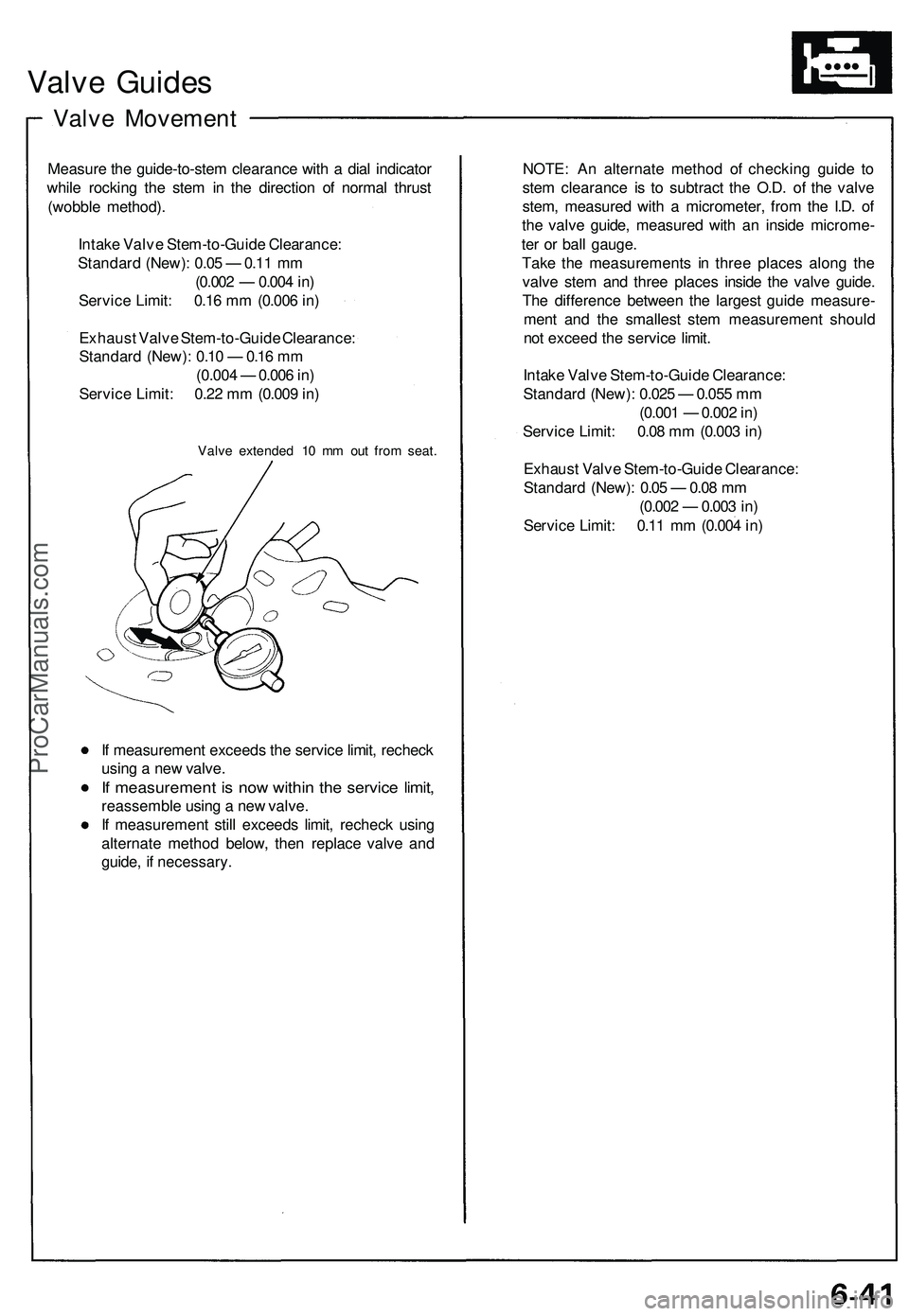
Measure the guide-to-stem clearance with a dial indicator
while rocking the stem in the direction of normal thrust
(wobble method).
Intake Valve Stem-to-Guide Clearance:
Standard (New): 0.05 — 0.11 mm
(0.002 — 0.004 in)
Service Limit: 0.16 mm (0.006 in)
Exhaust Valve Stem-to-Guide Clearance:
Standard (New): 0.10 — 0.16 mm
(0.004 — 0.006 in)
Service Limit: 0.22 mm (0.009 in)
Valve extended 10 mm out from seat.
If measurement exceeds the service limit, recheck
using a new valve.
If measurement is now within the service limit,
reassemble using a new valve.
If measurement still exceeds limit, recheck using
alternate method below, then replace valve and
guide, if necessary.
NOTE: An alternate method of checking guide to
stem clearance is to subtract the O.D. of the valve
stem, measured with a micrometer, from the I.D. of
the valve guide, measured with an inside microme-
ter or ball gauge.
Take the measurements in three places along the
valve stem and three places inside the valve guide.
The difference between the largest guide measure-
ment and the smallest stem measurement should
not exceed the service limit.
Intake Valve Stem-to-Guide Clearance:
Standard (New): 0.025 — 0.055 mm
(0.001 — 0.002 in)
Service Limit: 0.08 mm (0.003 in)
Exhaust Valve Stem-to-Guide Clearance:
Standard (New): 0.05 — 0.08 mm
(0.002 — 0.003 in)
Service Limit: 0.11 mm (0.004 in)ProCarManuals.com
Page 586 of 1503
PGM-FI System
System Description (cont'd)
3. Fuel Cut-off Control
During deceleration with the throttle valve closed, current to the fuel injectors is cut off to improve fuel economy at
speeds over 1,500 rpm.
Fuel cut-off action also takes place when engine speed exceeds 8,300 rpm, regardless of the position of the throttle
valve, to protect the engine from over-revving.
4. A/C Compressor Clutch Relay
When the ECM receives a demand for cooling from the air conditioning system, it delays the compressor from being
energized, and enriches the mixture to assure smooth translation to the A/C mode.
5. Evaporative Emission (EVAP) Purge Control Solenoid Valve
When the engine coolant temperature is below 153°F (67°C), the ECM controls the EVAP purge control solenoid valve
which cuts vacuum to the EVAP purge control canister diaphragm.
6. Intake Air Bypass (IAB) Control Solenoid Valve
When the engine speed is below 4,800 rpm, the IAB control solenoid valve is activated by a signal from the ECM. Intake
air then flows through the smaller chamber, and high torque is delivered. To increase air flow at engine speeds higher
than 4,800 rpm, the solenoid valve is deactivated by the ECM, and the intake air flows through the larger chamber.
7. Exhaust Gas Recirculation (EGR) Control Solenoid Valve
When the EGR is required for control of oxides of nitrogen (NOx) emissions, the ECM supplies ground to the EGR
control solenoid valve which supplies regulated vacuum to the EGR valve.
ECM Fail-safe/Back-up Functions
1. Fail-Safe Function
When an abnormality occurs in a signal from a sensor, the ECM ignores that signal and assumes a pre-programmed
valve for that sensor that allows the engine to continue to run.
2. Back-up Function
When an abnormality occurs in the ECM itself, the fuel injectors are controlled by a back-up circuit independent of the
system in order to permit minimal driving.
3. Self-diagnosis Function [Malfunction Indicator Lamp (MIL)]
When an abnormality occurs in a signal from a sensor, the ECM lights the MIL and stores the diagnostic trouble code
in erasable memory. When the ignition is initially turned on, the ECM supplies ground for the MIL for two seconds to
check the MIL bulb condition.
4. Two Trip Detection Method
To prevent false indications, the Two Trip Detection Method is used for the H02S, fuel metering-related, idle control
system, ECT sensor, EGR system self-diagnostic functions and EVAP control system. When an abnormality occurs,
the ECM stores it in its memory. When the same abnormality recurs after the ignition switch is turned OFF and ON (II)
again, the ECM informs the driver by lighting the MIL.
However, to ease troubleshooting, this function is cancelled when you short the service check connector. The MIL will
then blink immediately when an abnormality occurs.
5. Two (or three) Driving Cycle Detection Method
A "Driving Cycle" consists of starting the engine, beginning closed loop operation, and stopping the engine. If misfir-
ing that increases emissions or EVAP control system malfunction is detected during two consecutive driving cycles,
or TWC deterioration is detected during three consecutive driving cycles, the ECM turns the MIL on.
However,
to
ease
troubleshooting,
this
function
is
cancelled when
you
short
the
service check connector.
The MIL
will
then blink immediately when an abnormality occurs.ProCarManuals.com
Page 822 of 1503
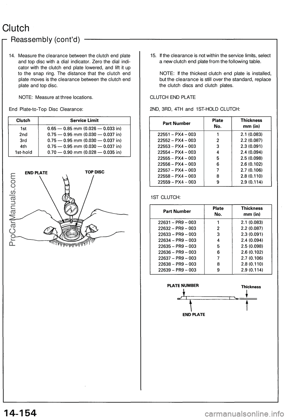
14. Measure the clearance between the clutch end plate
and top disc with a dial indicator. Zero the dial indi-
cator with the clutch end plate lowered, and lift it up
to the snap ring. The distance that the clutch end
plate moves is the clearance between the clutch end
plate and top disc.
NOTE: Measure at three locations.
End Plate-to-Top Disc Clearance:
Reassembly (cont'd)
Clutch
15. If the clearance is not within the service limits, select
a new clutch end plate from the following table.
NOTE: If the thickest clutch end plate is installed,
but the clearance is still over the standard, replace
the clutch discs and clutch plates.
CLUTCH END PLATE
2ND, 3RD, 4TH and 1ST-HOLD CLUTCH:
1ST CLUTCH:ProCarManuals.com
Page 902 of 1503
Self-Diagnosis Function
The EPS control unit monitors the system inputs and outputs, and the driving current of the motor. If there is a problem in
the system, the control unit turns the system off by actuating the relay. Power assist stops and normal manual steering
operation resumes. The control unit also turns the EPS indicator light on to alert the driver, and memorizes the problem in
the form of a code. Connecting the terminals of the service check connector with the SCS service connector (special tool)
enables the EPS indicator light to blink the problem code when the ignition switch is turned on (II).
Unloader Control
If the steering wheel is turned fully and held in the full-lock position, the steering torque reaches the maximum point, and
an over-current flows to the motor. The control unit detects this and reduces the current flow to the motor.
Average Moving Current Control
The electric current flow to the motor is estimated from the current values detected by the current sensor, and the average
current is obtained at two second intervals. The motor driving current is suppressed when the average current value
exceeds a predetermined marginal value. The control unit regulates the motor current during continuous loading to sup-
press any excessive temperature rise in the motor.ProCarManuals.com
Page 1047 of 1503
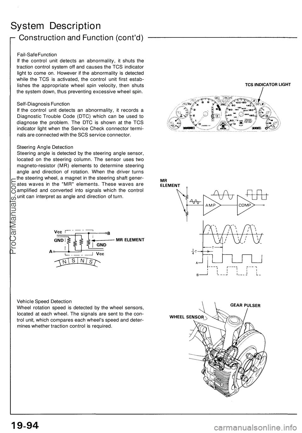
Construction and Function (cont'd)
System Description
Fail-Safe Function
If the control unit detects an abnormality, it shuts the
traction control system off and causes the TCS indicator
light to come on. However if the abnormality is detected
while the TCS is activated, the control unit first estab-
lishes the appropriate wheel spin velocity, then shuts
the system down, thus preventing excessive wheel spin.
Self-Diagnosis Function
If the control unit detects an abnormality, it records a
Diagnostic Trouble Code (DTC) which can be used to
diagnose the problem. The DTC is shown at the TCS
indicator light when the Service Check connector termi-
nals are connected with the SCS service connector.
Steering Angle Detection
Steering angle is detected by the steering angle sensor,
located on the steering column. The sensor uses two
magneto-resistor (MR) elements to determine steering
angle and direction of rotation. When the driver turns
the steering wheel, a magnet in the steering shaft gener-
ates waves in the "MR" elements. These waves are
amplified and converted into signals which the control
unit can interpret as angle and direction of turn.
Vehicle Speed Detection
Wheel rotation speed is detected by the wheel sensors,
located at each wheel. The signals are sent to the con-
trol unit, which compares each wheel's speed and deter-
mines whether traction control is required.ProCarManuals.com
Page 1052 of 1503
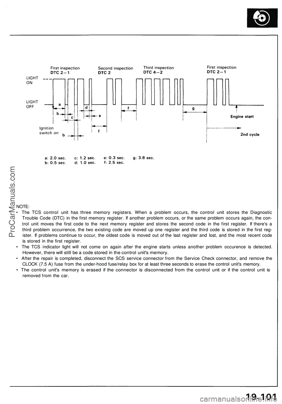
NOTE:
• The TCS control unit has three memory registers. When a problem occurs, the control unit stores the Diagnostic
Trouble Code (DTC) in the first memory register. If another problem occurs, or the same problem occurs again, the con-
trol unit moves the first code to the next memory register and stores the second code in the first register. If there's a
third problem occurrence, the two existing code are moved up one register and the third code is stored in the first reg-
ister. If problems continue to occur, the oldest code is moved out of the last register and lost, and the most recent code
is stored in the first register.
• The TCS indicator light will not come on again after the engine starts unless another problem occurence is detected.
However, there will still be a code stored in the control unit's memory.
• After the repair is completed, disconnect the SCS service connector from the Service Check connector, and remove the
CLOCK (7.5 A) fuse from the under-hood fuse/relay box for at least three seconds to erase the control unit's memory.
• The control unit's memory is erased if the connector is disconnected from the control unit or if the control unit is
removed from the car.ProCarManuals.com
Page 1308 of 1503
Safety Indicato r
Componen t Locatio n Inde x
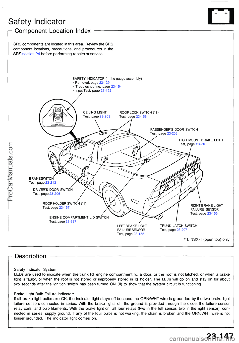
SRS component s ar e locate d in thi s area . Revie w th e SR S
componen t locations , precautions , an d procedure s i n th e
SR S sectio n 24 befor e performin g repair s o r service .
SAFET Y INDICATO R (I n th e gaug e assembly )
• Removal , pag e 23-12 9
• Troubleshooting , pag e 23-15 4
• Inpu t Test , pag e 23-15 2
ROOF LOC K SWITC H (*1 )
Test , pag e 23-15 6
PASSENGER' S DOO R SWITC H
Test , pag e 23-20 6
HIG H MOUN T BRAK E LIGH T
Test , pag e 23-21 3
CEILIN
G LIGH T
Test , pag e 23-20 3
BRAK E SWITC H
Test , pag e 23-21 3
DRIVER' S DOO R SWITC H
Test , pag e 23-20 6
ROO F HOLDE R SWITC H (*1 )
Test , pag e 23-15 7
ENGIN E COMPARTMEN T LI D SWITC H
Test , pag e 23-32 7 RIGH
T BRAK E LIGH T
FAILUR E SENSO R
Test , pag e 23-15 5
LEF T BRAK E LIGH T
FAILUR E SENSO R
Test , pag e 23-15 5 TRUN
K LATC H SWITC H
Test , pag e 23-20 7
1: NSX- T (ope n top ) onl y
Descriptio n
Safety Indicato r System :
LEDs ar e use d t o indicat e whe n th e trun k lid , engin e compartmen t lid , a door , o r th e roo f i s no t latched , o r whe n a brak e
light i s faulty , o r whe n th e roo f i s no t store d o r improperl y store d i n it s holder . Th e LED s wil l g o o n an d sta y o n fo r abou t
tw o second s afte r th e ignitio n switc h ha s bee n turne d O N (II ) t o sho w tha t th e syste m circui t i s functioning .
Brak e Ligh t Bul b Failur e Indicator :
If al l brak e ligh t bulb s ar e OK , th e indicato r ligh t stay s of f becaus e th e ORN/WH T wir e is grounde d b y th e tw o brak e ligh t
failur e sensor s connecte d i n series . Wit h th e brak e light s off , th e groun d i s provide d throug h th e diode , th e failur e senso r
rela y coils , an d bul b filaments . Wit h th e brak e ligh t on , al l fou r relay s (tw o i n th e lef t sensor , tw o i n th e righ t sensor) , con -
necte d i n series , suppl y ground . I f an y o f th e fou r bulb s i s no t working , th e chai n i s broke n an d th e ORN/WH T wir e i s no t
longe r grounded . Th e indicato r ligh t come s on .
ProCarManuals.com