Page 371 of 1503

4-2
For the details of lubrication points and types of lubricants to be appl\
ied, refer to the illustrated index and various work
procedures (such as Assembly/Reassembly, Replacement, Overhaul, Install\
ation, etc.) contained in each section.
*1: Always use Honda Manual Transmission Fluid (MTF). Using motor oil can \
cause stiffer shifting because it does not contain theproper additives.
*2: Always use Honda ATF-Z1 (ATF). Using a non-Honda ATF can affect shift \
quality.
*3: Always use Honda Heavy Duty DOT3 Brake Fluid. Using a non-Honda brake fl\
uid can cause corrosion and decrease the life of the system.
Lubrication Points
No.LUBRICATION POINTSLUBRICANT
1Honda Motor Oil: P/N 08798-9015.
Look for the API Certification seal shown below. Make sure
it says “For Gasoline Engines.”
2TransmissionHonda MTF*1(P/N 08798-9016)
3Brake system (including anti-lock brake system)Honda Heavy Duty DOT3 Brake Fluid*3(P/N 08798-9008)4Clutch line
5Change lever pivots (M/T)Super High Temp Urea Grease (P/N 08798-9002)6Release fork (M/T)
8
9
10
11
12
13
14
15
16
17
18
19
20
21Steering boots
Steering ball joints
Select lever (A/T)
Pedal linkage
Intermediate shaft
Brake master power pushrod
Fuel fill door
Clutch master cylinder pushrod
Tilt lever
Parking brake cable end
Door hinges upper and lower
Door opening detents
Hood hinges and lock
Rear hatch latch
Multipurpose grease
24
22
23
Caliper piston boot, caliper pins, and boots
Shift cable end and select cable end (A/T)
Throttle cable ends
Honda Caliper Grease (P/N 08C30-B0234M)
Silicone grease
25Air conditioning compressorCompressor oil:
DENSO: ND-OIL8 (P/N 38897-PR7-A01AH or 38899-PR7-A01)
For Refrigerant: HFC-134a (R-134a)
Manual
Honda ATF-Z1 (ATF)*2(P/N 08200-9001)Automatic
7Steering gearboxSteering grease (P/N 08733-B070E)
Engine
API CERTIFICATION SEAL
Recommended engine oil
Engine oil viscosity for
ambient temperature ranges
*05-NSX (61SW004)SEC04(01-10) 9/22/04 1:49 PM Page 4-2
ProCarManuals.com
Page 982 of 1503

Inspection and Adjustment
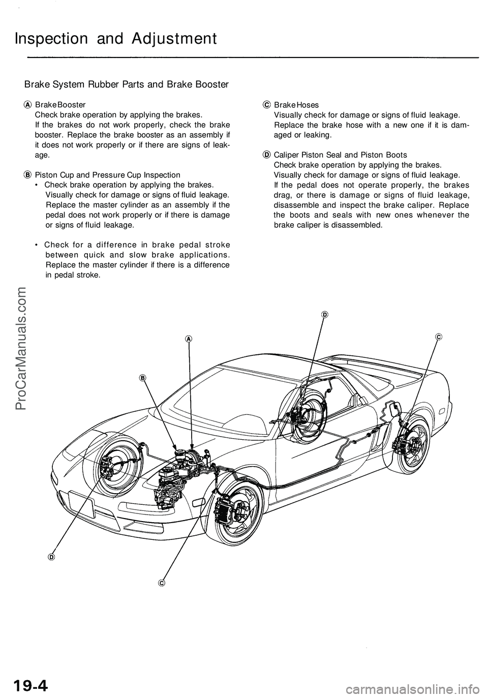
Brake System Rubber Parts and Brake Booster
Brake Booster
Check brake operation by applying the brakes.
If the brakes do not work properly, check the brake
booster. Replace the brake booster as an assembly if
it does not work properly or if there are signs of leak-
age.
Piston Cup and Pressure Cup Inspection
• Check brake operation by applying the brakes.
Visually check for damage or signs of fluid leakage.
Replace the master cylinder as an assembly if the
pedal does not work properly or if there is damage
or signs of fluid leakage.
• Check for a difference in brake pedal stroke
between quick and slow brake applications.
Replace the master cylinder if there is a difference
in pedal stroke.
Brake Hoses
Visually check for damage or signs of fluid leakage.
Replace the brake hose with a new one if it is dam-
aged or leaking.
Caliper Piston Seal and Piston Boots
Check brake operation by applying the brakes.
Visually check for damage or signs of fluid leakage.
If the pedal does not operate properly, the brakes
drag, or there is damage or signs of fluid leakage,
disassemble and inspect the brake caliper. Replace
the boots and seals with new ones whenever the
brake caliper is disassembled.ProCarManuals.com
Page 1363 of 1503

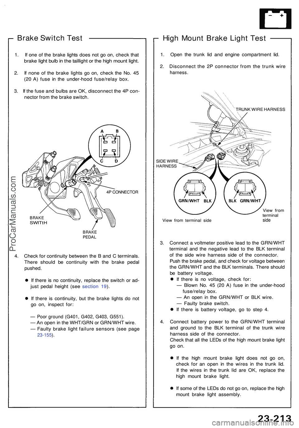
Brake Switc h Tes t
1. I f on e o f th e brak e light s doe s no t g o on , chec k tha t
brak e ligh t bul b in th e tailligh t o r th e hig h moun t light .
2. I f non e o f th e brak e light s g o on , chec k th e No . 4 5
(2 0 A ) fus e i n th e under-hoo d fuse/rela y box .
3 . I f th e fus e an d bulb s ar e OK , disconnec t th e 4 P con -
necto r fro m th e brak e switch .
4P CONNECTO R
BRAKESWITtH
BRAK EPEDAL
4. Chec k fo r continuit y betwee n th e B an d C terminals .
Ther e shoul d b e continuit y wit h th e brak e peda l
pushed .
I f ther e i s n o continuity , replac e th e switc h o r ad -
jus t peda l heigh t (se e sectio n 19 ).
I f ther e i s continuity , bu t th e brak e light s d o no t
g o on , inspec t for :
— Poo r groun d (G401 , G402 , G403 , G551) .
— An ope n in th e WHT/GR N o r GRN/WH T wire .
— Fault y brak e ligh t failur e sensor s (se e pag e
23-155 ).
Hig h Moun t Brak e Ligh t Tes t
1. Ope n th e trun k li d an d engin e compartmen t lid .
2 . Disconnec t th e 2 P connecto r fro m th e trun k wir e
harness .
TRUNK WIR E HARNES S
SID E WIR E
HARNES S
View fro m termina l sid e Vie
w fro m
termina lside
3. Connec t a voltmete r positiv e lea d t o th e GRN/WH T
termina l an d th e negativ e lea d t o th e BL K termina l
o f th e sid e wir e harnes s sid e o f th e connector .
Pus h th e brak e pedal , an d chec k fo r voltag e betwee n
th e GRN/WH T an d th e BL K terminals . Ther e shoul d
b e batter y voltage .
I f ther e i s n o voltage , chec k for :
— Blow n No . 4 5 (2 0 A ) fus e i n th e under-hoo d
fuse/rela y box .
— A n ope n i n th e GRN/WH T o r BL K wire .
— Fault y brak e switch .
I f ther e i s batter y voltage , g o t o ste p 4 .
4 . Connec t batter y powe r t o th e GRN/WH T termina l
an d groun d t o th e BL K termina l o f th e trun k wir e
harnes s sid e o f th e connector .
Chec k tha t al l th e LED s o f th e hig h moun t brak e ligh t
go on .
If th e hig h moun t brak e ligh t doe s no t g o on ,
chec k fo r a n ope n i n th e wire s i n th e trun k lid .
I f th e wire s i n th e trun k li d ar e OK , replac e th e
hig h moun t brak e light .
I f som e o f th e LED s d o no t g o on , replac e th e hig h
moun t brak e ligh t assembly .
ProCarManuals.com