Page 168 of 1503
CAUTION: (if roof maintenance is required)
�Be careful not ot bend the edge of the roof opening.
�The roof is made of aluminum alloy. Take care not to dent or scratch the roof. If there is a minor dent or scratch on the roof, repair
the roof with putty (refer to the body repair manual).
�When replacing the component parts of the roof, place the roof on an appropriate pad to prevent damage.
NOTE:
�Have an assistant help remove the roof.
�When the roof is stored on the engine cover, lock the roof cover securely.
�When installing the roof, secure it by turning both roof side lock handles. Make sure they are locked securely.
ProCarManuals.com
Page 385 of 1503

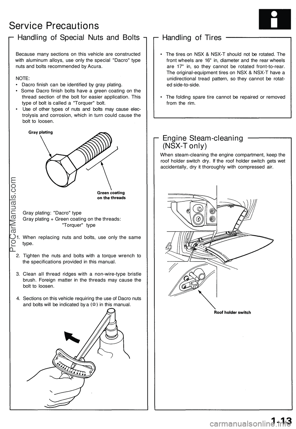
Service Precautions
Handling of Special Nuts and Bolts
Handling of Tires
• The tires on NSX & NSX-T should not be rotated. The
front wheels are 16" in, diameter and the rear wheels
are 17" in, so they cannot be rotated front-to-rear.
The original-equipment tires on NSX & NSX-T have a
unidirectional tread pattern, so they cannot be rotat-
ed side-to-side.
• The folding spare tire cannot be repaired or removed
from the rim.
Engine Steam-cleaning
(NSX-T only)
When steam-cleaning the engine compartment, keep the
roof holder switch dry. If the roof holder switch gets wet
accidentally, dry it thoroughly with compressed air.
Because many sections on this vehicle are constructed
with aluminum alloys, use only the special "Dacro" type
nuts and bolts recommended by Acura.
NOTE:
• Dacro finish can be identified by gray plating.
• Some Dacro finish bolts have a green coating on the
thread section of the bolt for easier application. This
type of bolt is called a "Torquer" bolt.
• Use of other types of nuts and bolts may cause elec-
trolysis and corrosion, which in turn could cause the
bolt to loosen.
Gray plating: "Dacro" type
Gray plating + Green coating on the threads:
"Torquer" type
1. When replacing nuts and bolts, use only the same
type.
2. Tighten the nuts and bolts with a torque wrench to
the specifications provided in this manual.
3. Clean all thread ridges with a non-wire-type bristle
brush. Foreign matter in the threads may cause the
bolt to loosen.
4. Sections on this vehicle requiring the use of Dacro nuts
and bolts will be indicated by a in this manual.ProCarManuals.com
Page 1059 of 1503

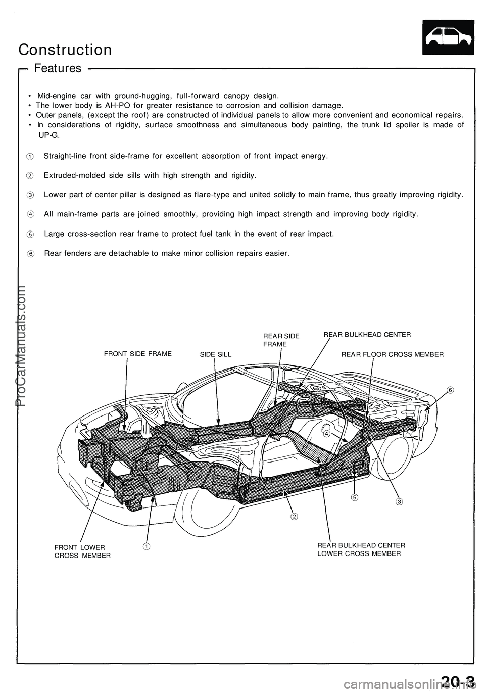
Construction
• Mid-engin e ca r wit h ground-hugging , full-forwar d canop y design .
• Th e lowe r bod y i s AH-P O fo r greate r resistanc e t o corrosio n an d collisio n damage .
• Oute r panels , (excep t th e roof ) ar e constructe d o f individua l panel s t o allo w mor e convenien t an d economica l repairs .
• I n consideration s o f rigidity , surfac e smoothnes s an d simultaneou s bod y painting , th e trun k li d spoile r i s mad e of
UP-G .
Straight-lin e fron t side-fram e fo r excellen t absorptio n o f fron t impac t energy .
Extruded-molde d sid e sill s wit h hig h strengt h an d rigidity .
Lowe r par t of cente r pilla r i s designe d a s flare-typ e an d unite d solidl y t o mai n frame , thu s greatl y improvin g rigidity .
Al l main-fram e part s ar e joine d smoothly , providin g hig h impac t strengt h an d improvin g bod y rigidity .
Larg e cross-sectio n rea r fram e t o protec t fue l tan k i n th e even t o f rea r impact .
Rear fender s ar e detachabl e t o mak e mino r collisio n repair s easier .
REAR SID E
FRAM E
FRON T SID E FRAM E REA
R BULKHEA D CENTE R
REA R FLOO R CROS S MEMBE R
FRON T LOWE R
CROS S MEMBE R REA
R BULKHEA D CENTE R
LOWE R CROS S MEMBE R
Features
SIDE SIL L
ProCarManuals.com
Page 1060 of 1503
Construction
Composition
REAR HATCH
FRAME
TRUNK LID (#6000)
HOOD
(#6000)
SIDE SILL (#6000)
REAR FENDER (#6000)
Body Composites
(#5000)
DOOR (#6000)
FRONT FENDER (#6000)
Types of aluminum alloys for pressings:
ROOF PANEL
(#6000)ProCarManuals.com
Page 1121 of 1503
Rear Hatch/Engine Cover
Replacement/Adjustment
CAUTION: Use fender covers to avoid damaging painted surfaces.
1. Remove the engine cover.
2. Remove the connector cover, and disconnect the rear defogger, antenna lead and ground cable connectors.
3. Remove the rear hatch assembly by removing the support strut mounting bolts and rear hatch mounting bolts.
NOTE:
• Have an assistant hold the rear hatch assembly when removing the support struts.
• Take care not to damage the roof panel and rear hatch glass.
4. Installation is the reverse of the removal procedure.
NOTE:
• Before tightening the mounting bolts, adjust the rear hatch assembly and striker.
• With the rear hatch assembly closed fully, check for water leaks.ProCarManuals.com
Page 1133 of 1503
Construction
Features
The reinforce d part s ar e locate d a s shown .
: Reinforce d parts .
ROOF PANE L
TRUNK FRON T
CROS S MEMBE R
DASHBOAR DUPPER CROS S
MEMBE R
FLOOR CROS S
MEMBE R
BULKHEA D
UPPERSTIFFENE R
CENTER PILLA RUPPERREINFORCEMEN T
CENTER PILLA RLOWER REINFORCEMEN T
LOWE R STIFFENE R
FRON T SID E
SIL L EXTENSIO N
LOWERREINFORCEMEN TUpperReinforcemen t
Uppe r stiffene r
Uppe r patc h
Oute r pane l Inne
r pilla r
Front Pilla r Sectio n
SIDE SIL LSTIFFENE R
ProCarManuals.com
Page 1134 of 1503
Roof Rai l Trim , Fron t an d Rea r
Replacemen t
CAUTION:
• Wea r glove s t o remov e an d instal l th e trim .
• Whe n pryin g wit h a fla t ti p screwdriver , wra p it wit h
protectiv e tap e t o preven t damage .
NOTE:
• Tak e car e no t t o scratc h th e trim .
• Remov e th e roof .
Fron t roo f rai l trim :
1 . Remov e th e sunviso r fro m eac h side .
Screw location , 4
SUNVISO R
2. Pul l awa y th e doo r trim , the n lowe r th e fron t pilla r
tri m b y detachin g th e clip s fro m eac h side . The n
remov e th e screws .
Screw locations , 4
Clip locations , 8
DOO R TRI M
3. Remov e th e fron t roo f rai l tri m b y slidin g i t rearward .
FRONT ROO F
RAI L TRI M
4. Installatio n i s th e revers e o f th e remova l procedure .
NOTE:
• I f necessary , replac e an y damage d clips .
• Mak e sur e th e doo r tri m is installe d securely .
(cont'd )
FRONT PILLA RTRIM
FRON
T ROO F
RAI L TRI M
Hoo k locations , 4
ProCarManuals.com
Page 1135 of 1503
Roof Rai l Trim , Fron t an d Rea r
Replacemen t (cont'd )
Rear roo f rai l trim :
1 . Remov e th e ceilin g ligh t (se e sectio n 23 ).
2 . Pul l awa y th e doo r trim , the n lowe r th e rea r pilla r
tri m b y detachin g th e clip s fro m eac h side . The n
remov e th e screws .
Screw locations , 2Cli p locations , 6
REA R ROO F
RAI L TRI M
DOO RTRIM
REA R PILLA RTRIM
3. Detac h th e clips , an d remov e th e rea r receive r
dampe r fro m eac h side .
REAR RECEIVE RDAMPER
>: Cli p locations , 2
REA R RECEIVE RDAMPER
REAR ROO FRAIL TRI M
4. Remov e th e rea r roo f rai l tri m b y slidin g i t forward .
REAR ROO FRAIL TRI M
5. Installatio n i s th e revers e o f th e remova l procedure .
NOTE:
• I f necessary , replac e an y damage d clips .
• Mak e sur e th e doo r tri m is installe d securely .
Hook locations , 4
ProCarManuals.com